-
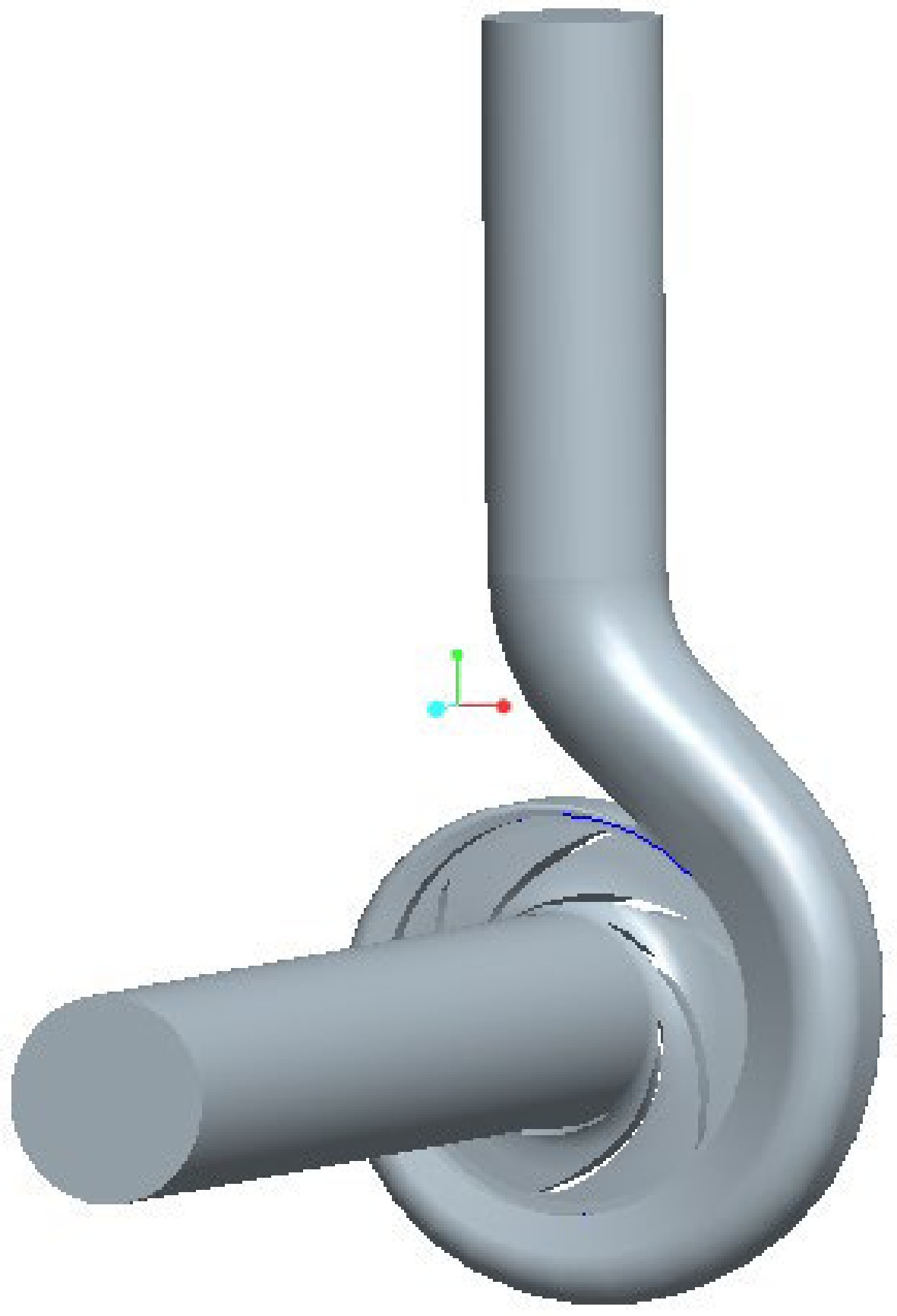
Figure 1.
Geometric model of the cryogenic pump.
-
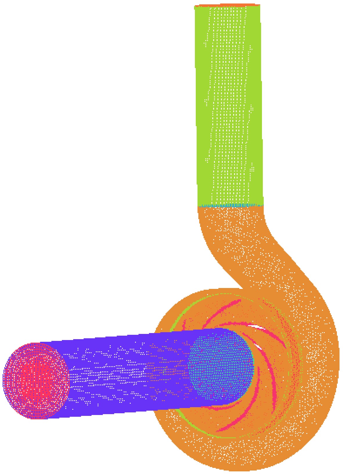
Figure 2.
Mesh of the cryogenic pump.
-
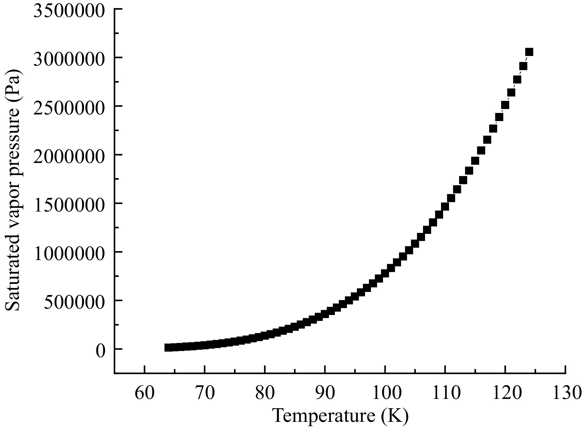
Figure 3.
The relationship between saturated vapor pressure and temperature.
-
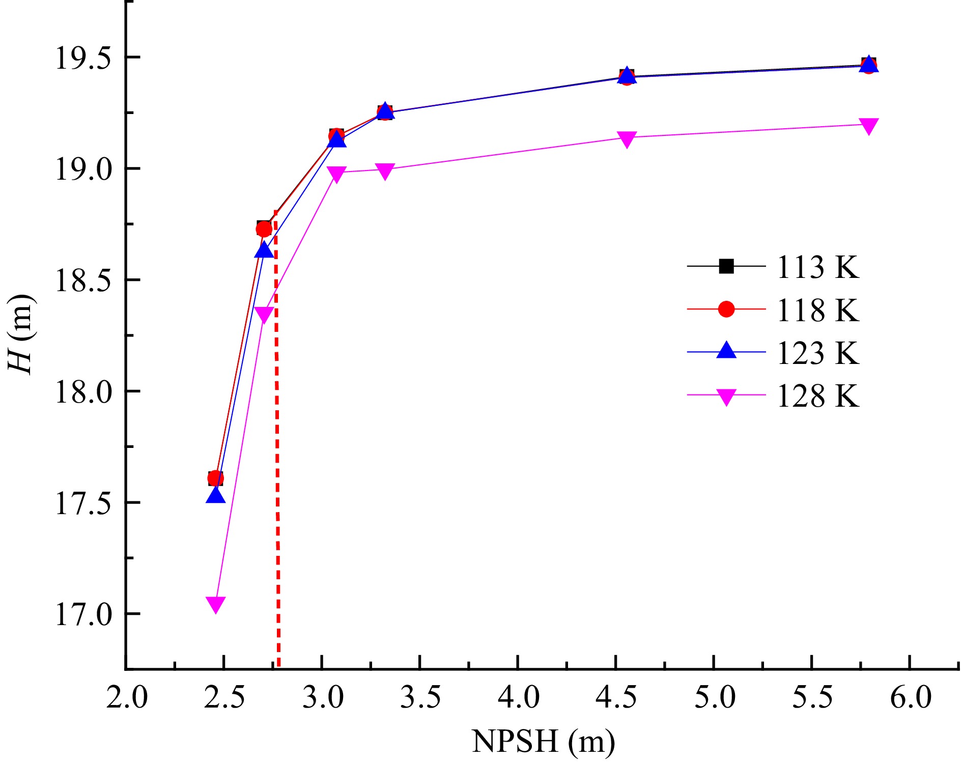
Figure 4.
Variation of head with the NPSH at different wall temperatures.
-
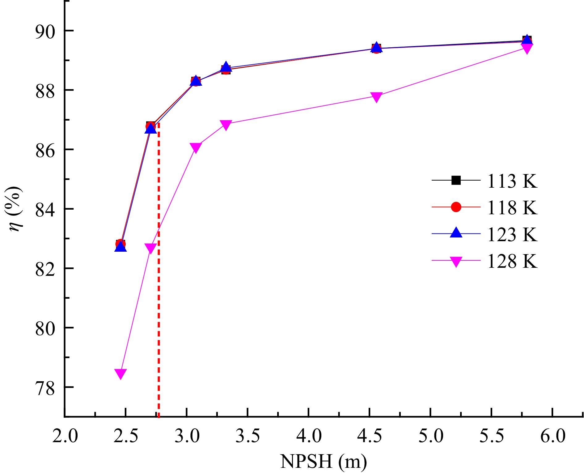
Figure 5.
Variation of efficiency with the NPSH at different inner wall temperatures.
-
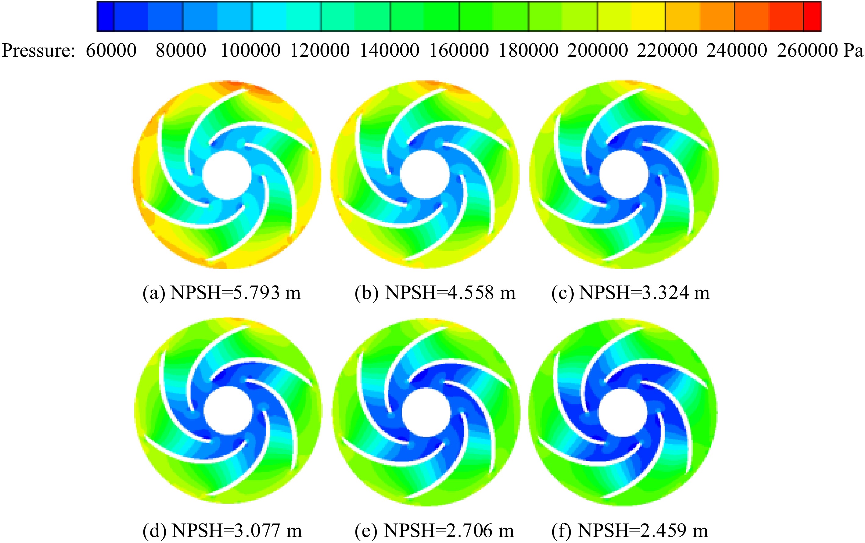
Figure 6.
Distribution of pressure in the impeller.
-
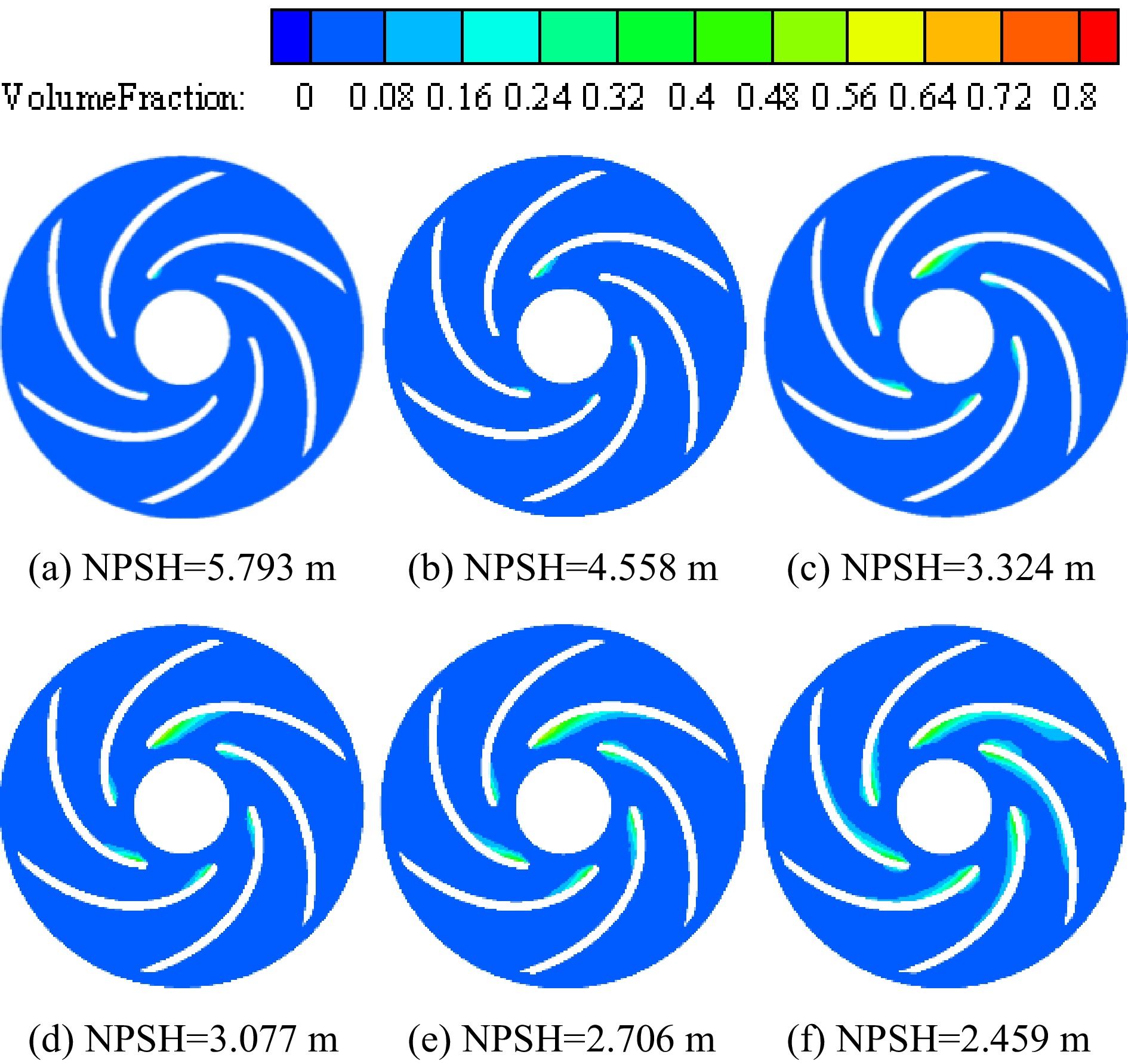
Figure 7.
Distribution of vapor volume fraction in the impeller.
-
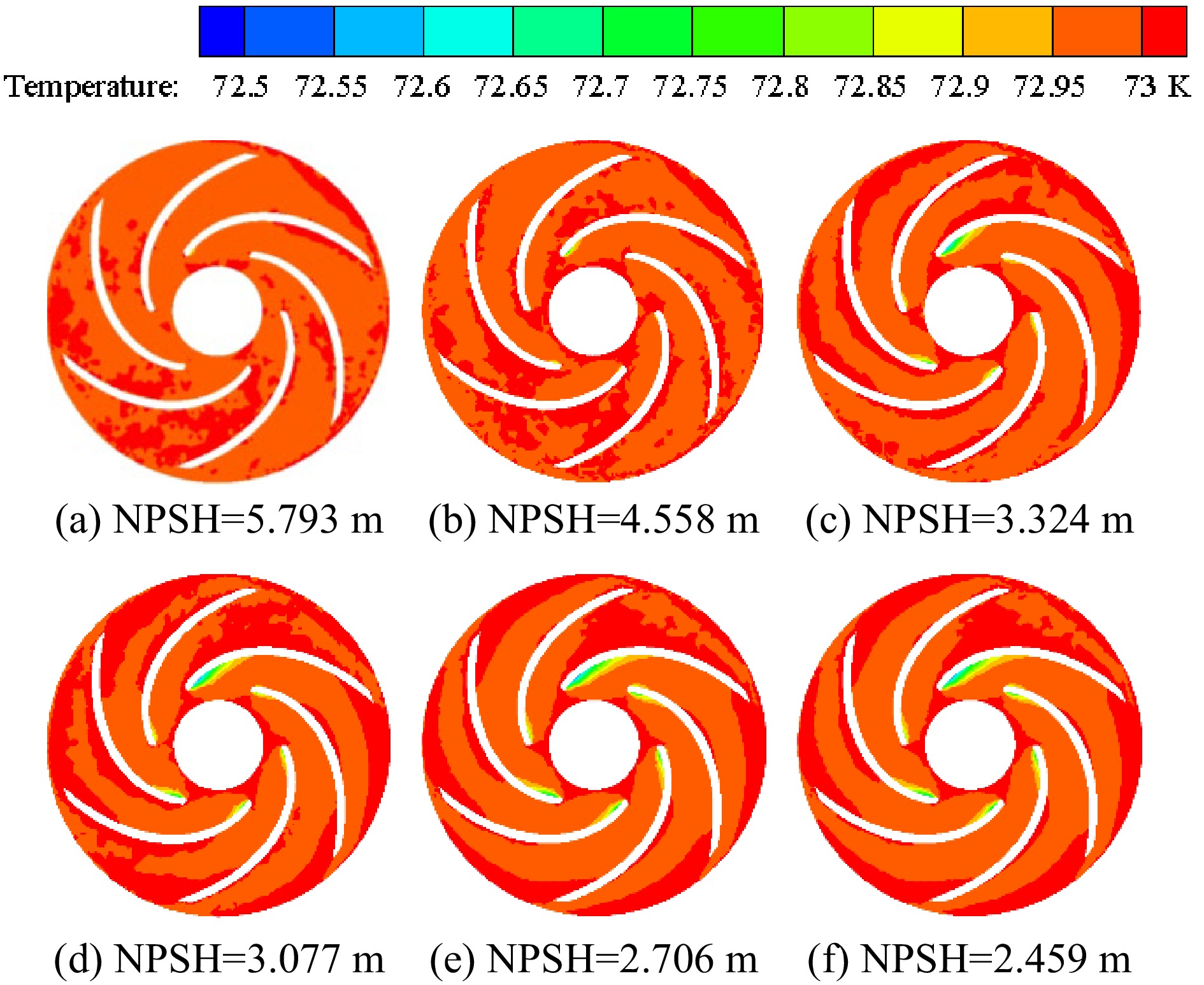
Figure 8.
Distribution of temperature in the impeller.
-
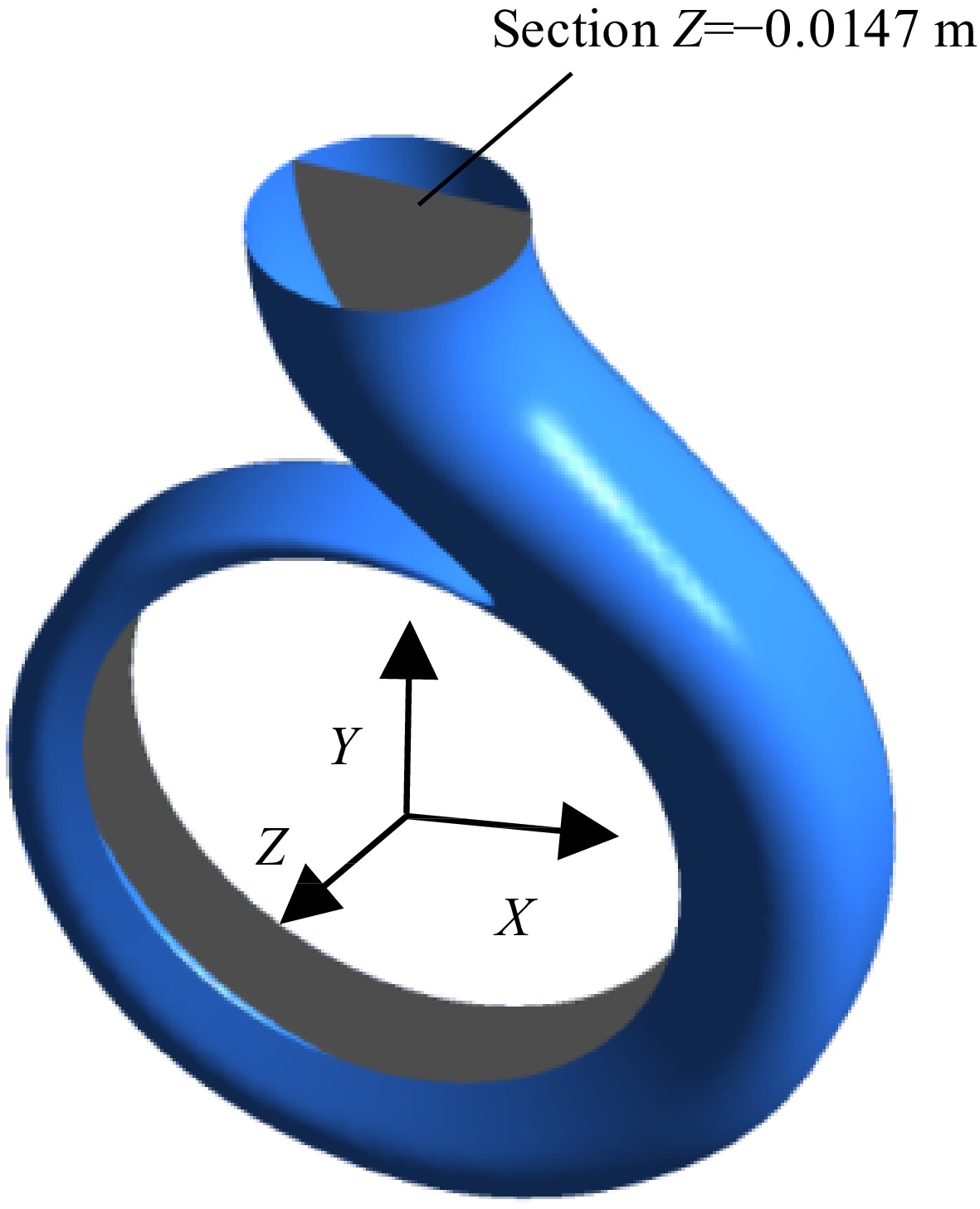
Figure 9.
Section Z = -0.0147 m in the volute.
-
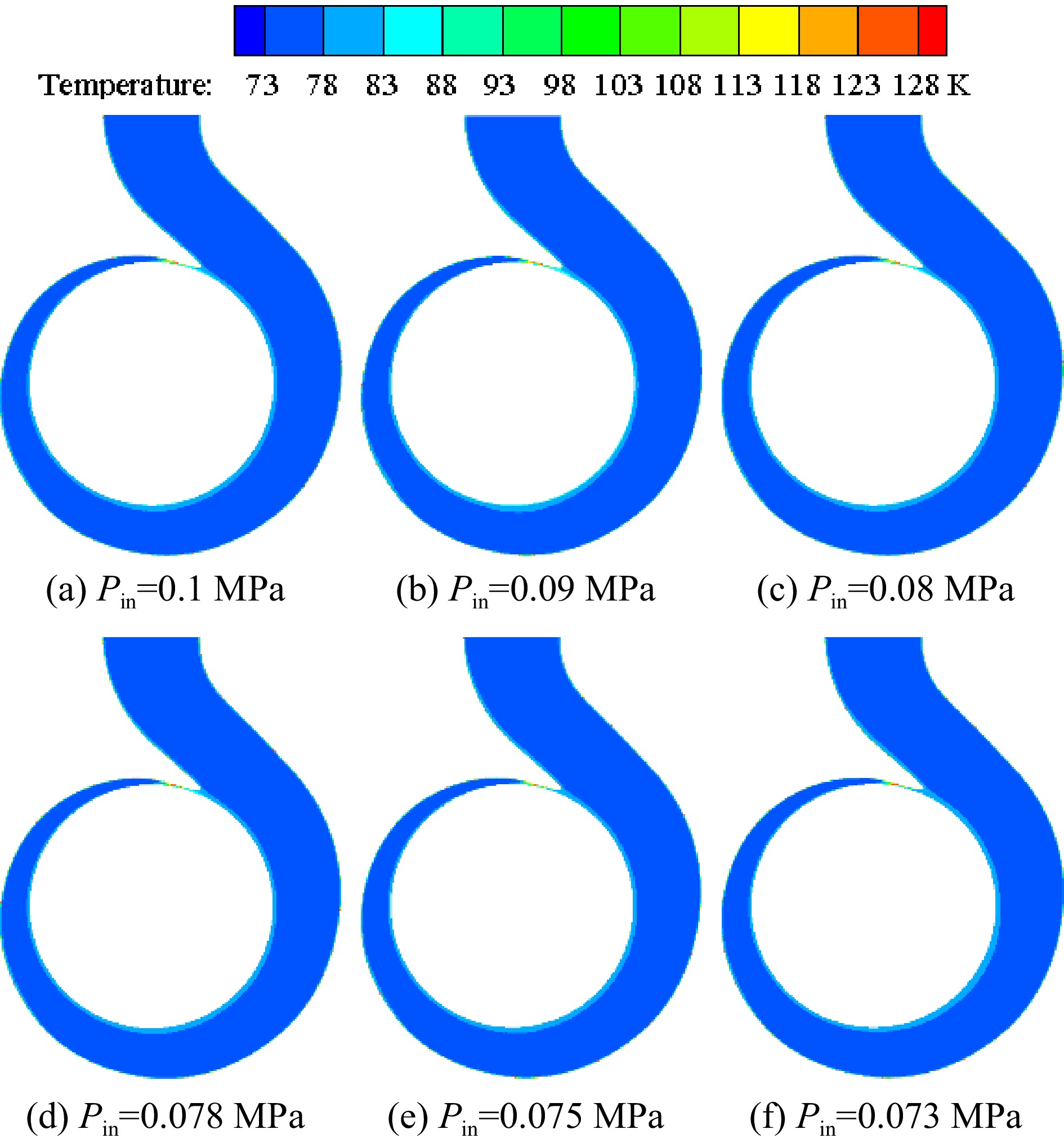
Figure 10.
Distribution of temperature on the volute section under different inlet pressures with the inner wall temperature of 128 K.
-
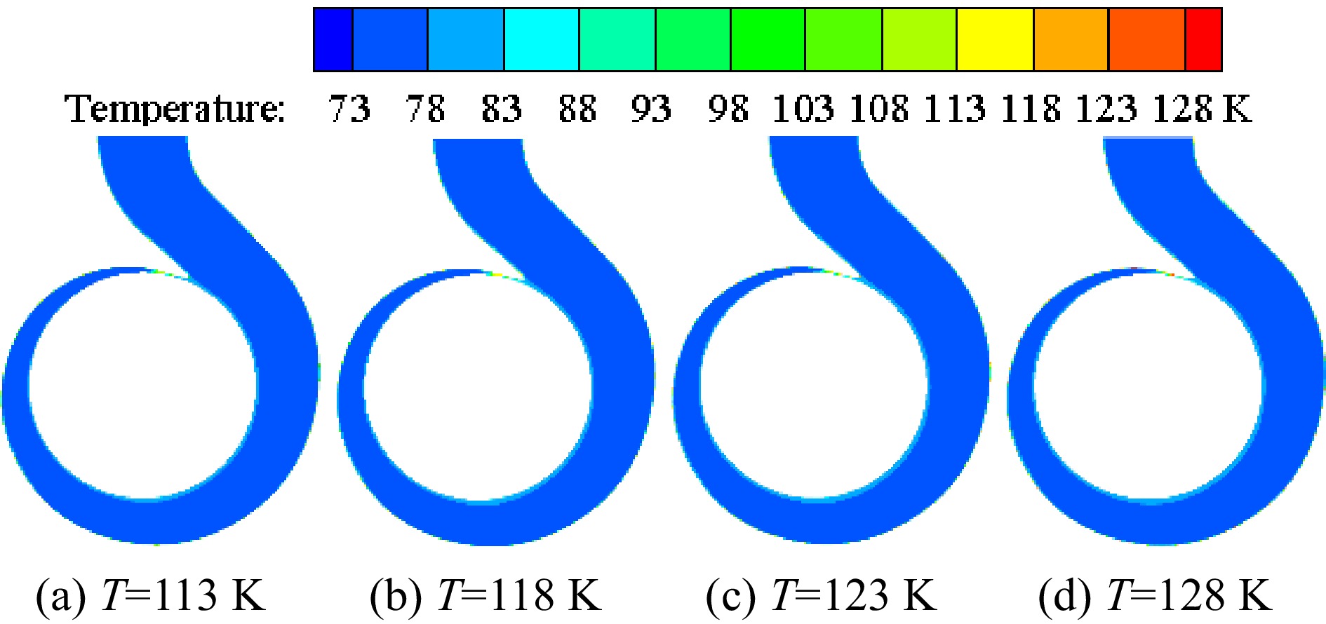
Figure 11.
Distribution of temperature on the volute section under different inner wall temperatures with the inlet pressure of 0.078 MPa.
-
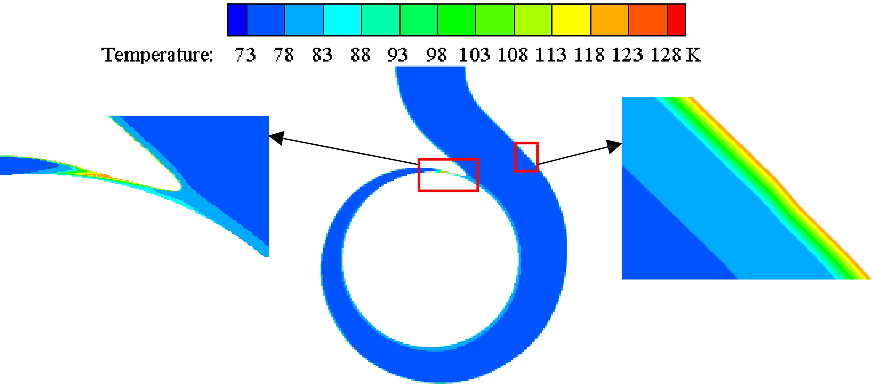
Figure 12.
Enlarged view of high temperature area at the inner wall temperature of 123 K with the inlet pressure of 0.078 MPa.
-
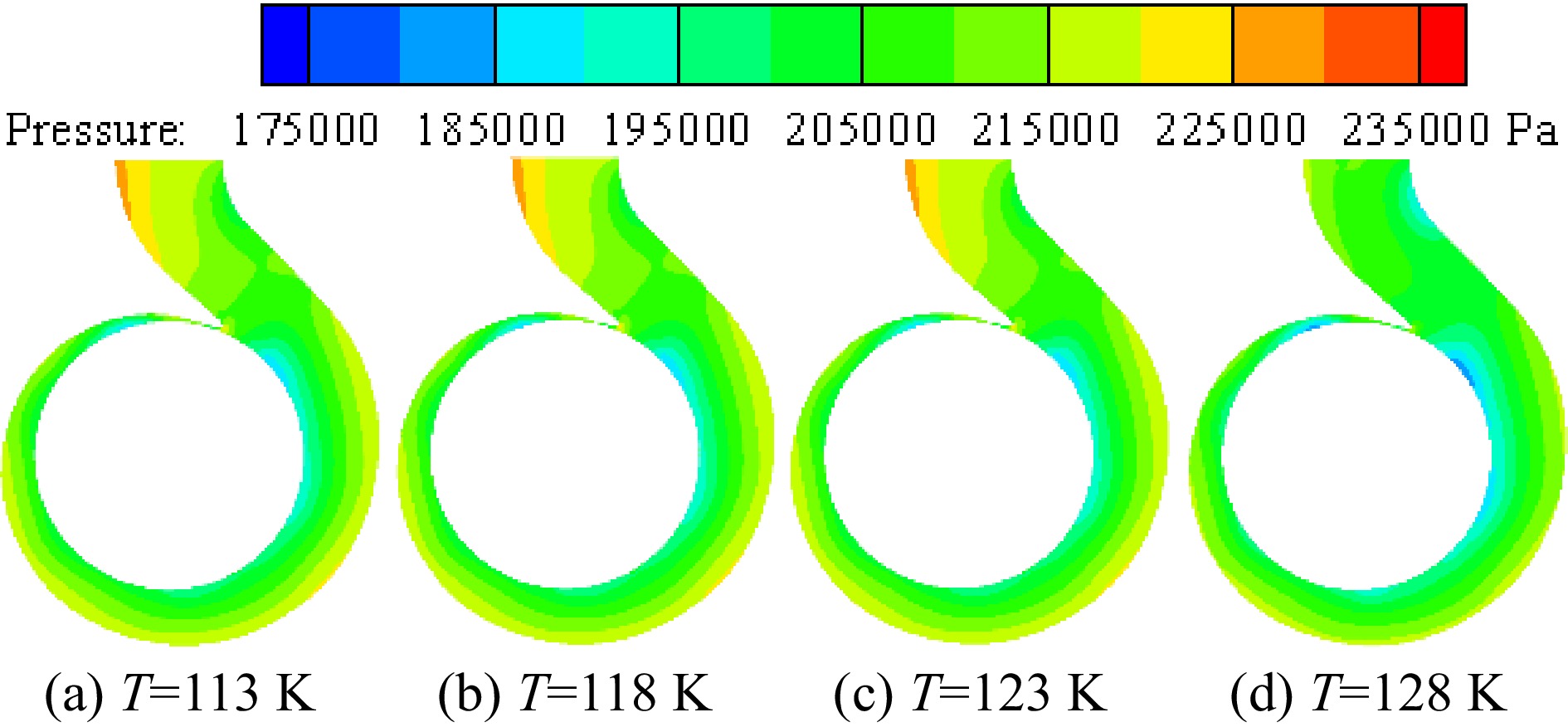
Figure 13.
Distribution of pressure at different inner wall temperatures with the inlet pressure of 0.078 MPa.
-
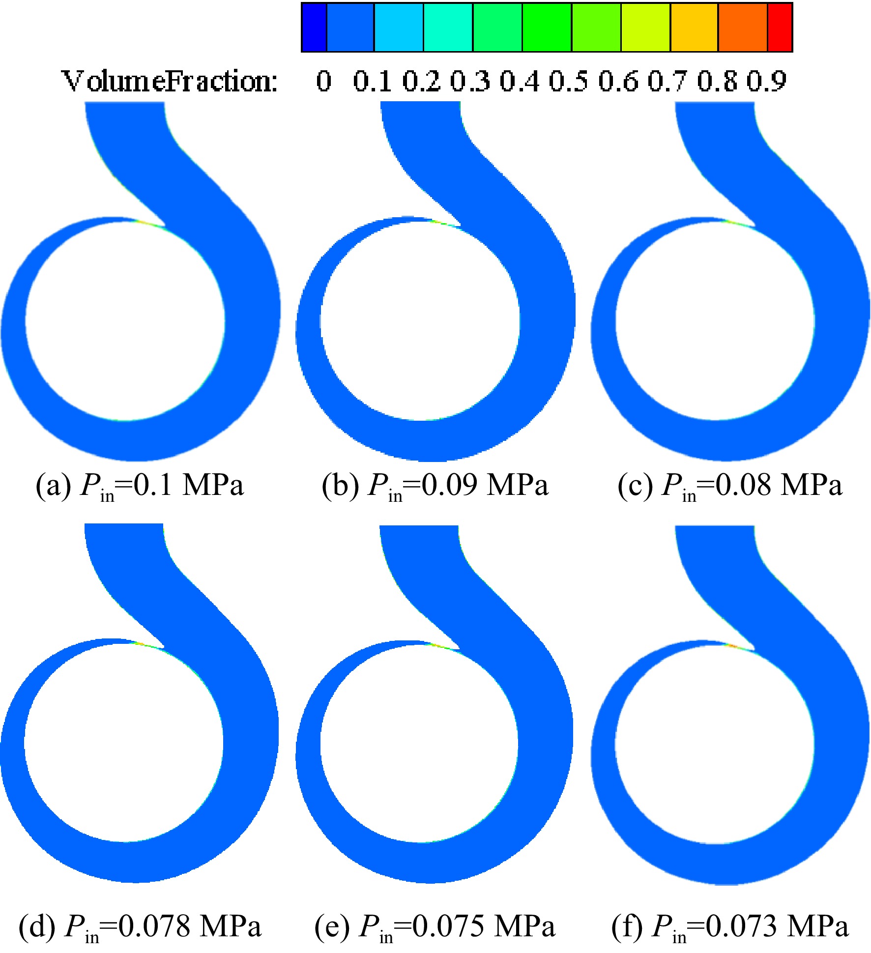
Figure 14.
Distribution of vapor volume fraction on the section of the volute at different pressures with the inner volute wall temperature of 128 K.
-
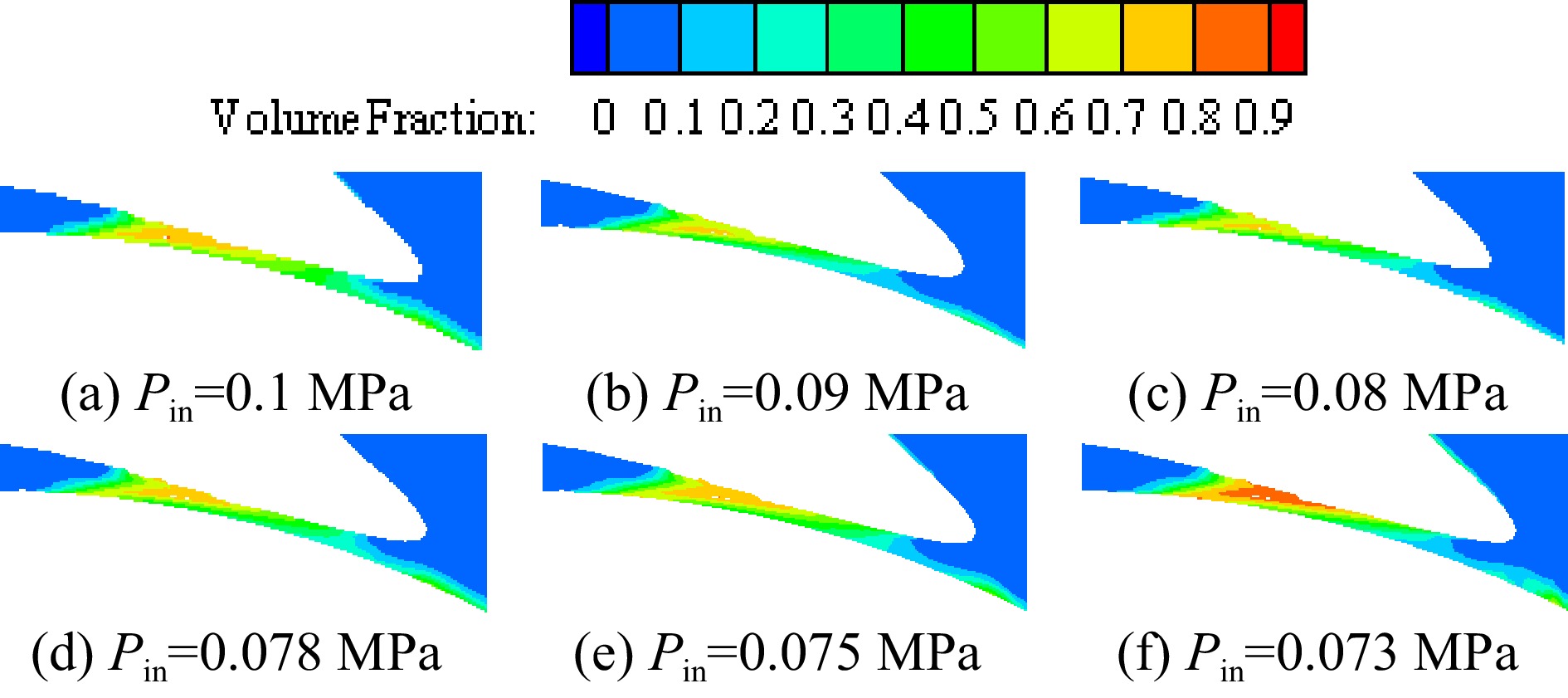
Figure 15.
Enlarged view of vapor volume fraction in the volute area at different inlet pressures with the inner volute wall temperature of 128 K.
-
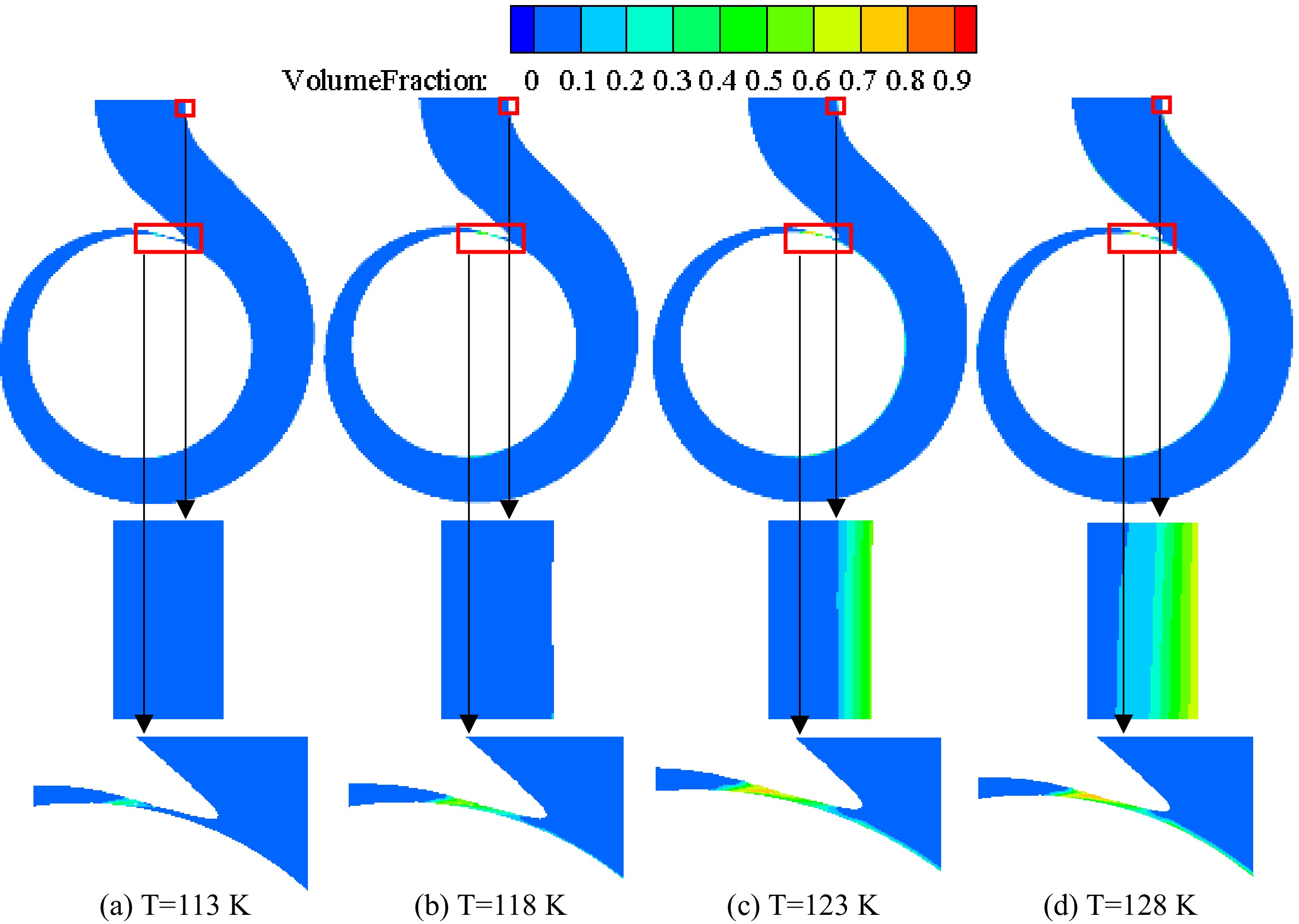
Figure 16.
Distribution of vapor volume fraction at different inner volute wall temperatures with the inlet pressure of 0.078 MPa.
-
Pump inlet diameter Di/
mmPump outlet diameter Do/
mmImpeller diameter
D2/mmNumber of blades
z/pcsBlade outlet width
b2/mmImpeller outlet width
b3/mm76 65 137 6 14 30 Table 1.
Main structural parameters of the cryogenic pump.
Figures
(16)
Tables
(1)