-
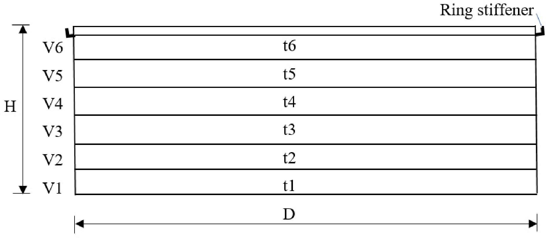
Figure 1.
Geometric characteristics of open-topped oil storage considered in this paper.
-
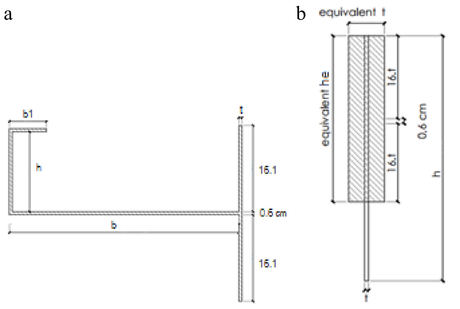
Figure 2.
Ring stiffener, (a) design according to API 650, (b) equivalent section[22].
-
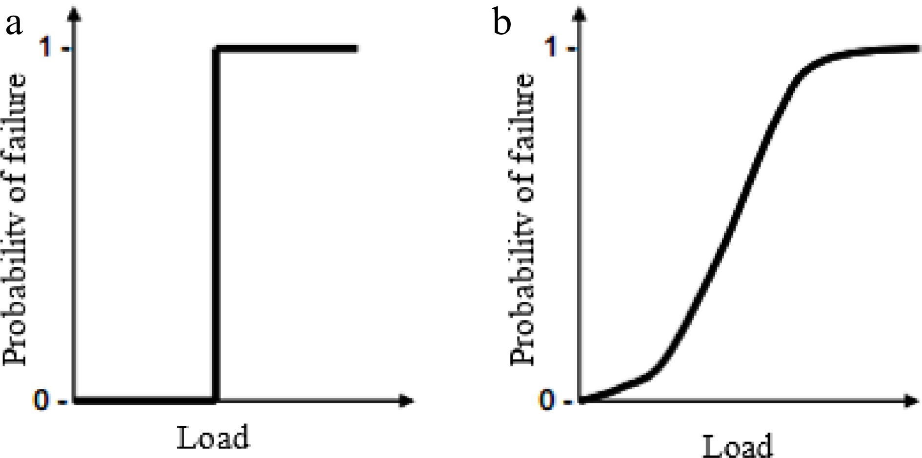
Figure 3.
Examples of fragility curves, (a) step-function, (b) 'S' shape function.
-

Figure 4.
Damage computed for a tank with D = 45 m and H = 12 m. (a) Deflected shape for damage DS1; (b) Equilibrium path for node A (DS1); (c) Deflected shape for damage DS2 (critical mode).
-
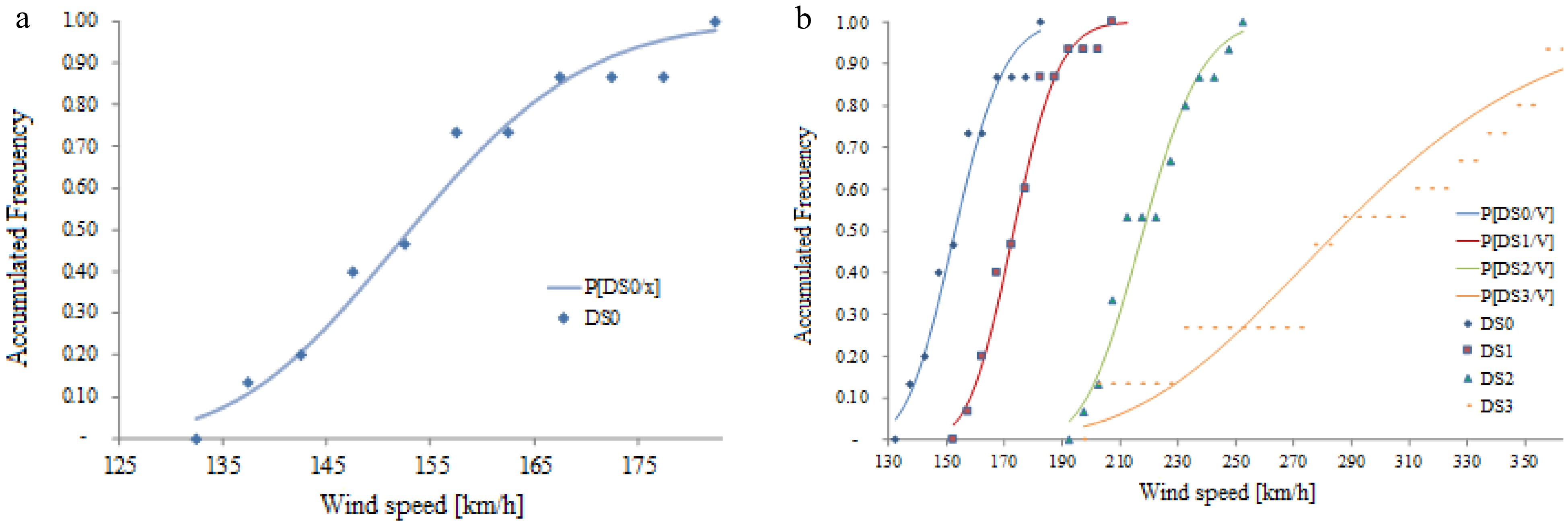
Figure 5.
Probability of reaching a damage level P[DSi/V], (a) DS0, (b) DS0, DS1, DS2 and DS3.
-
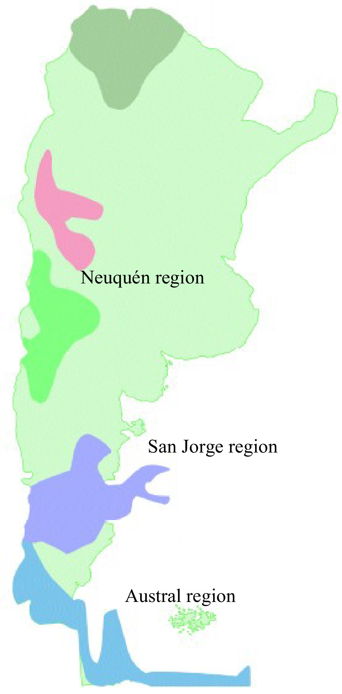
Figure 6.
Oil producing regions in Argentina. (Adapted from IAPG[47]).
-
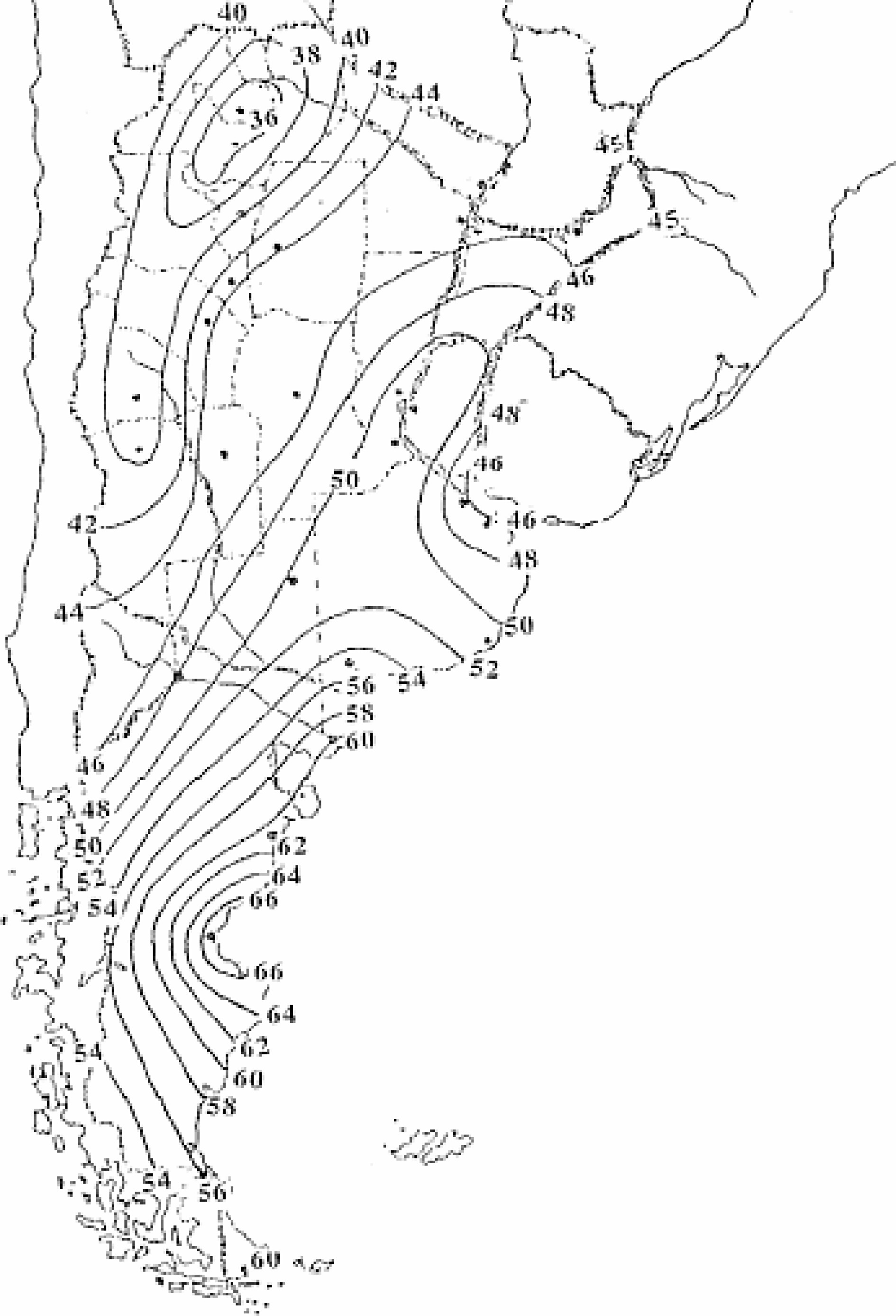
Figure 7.
Wind speed map of Argentina. (Adapted from CIRSOC 102[45]).
-
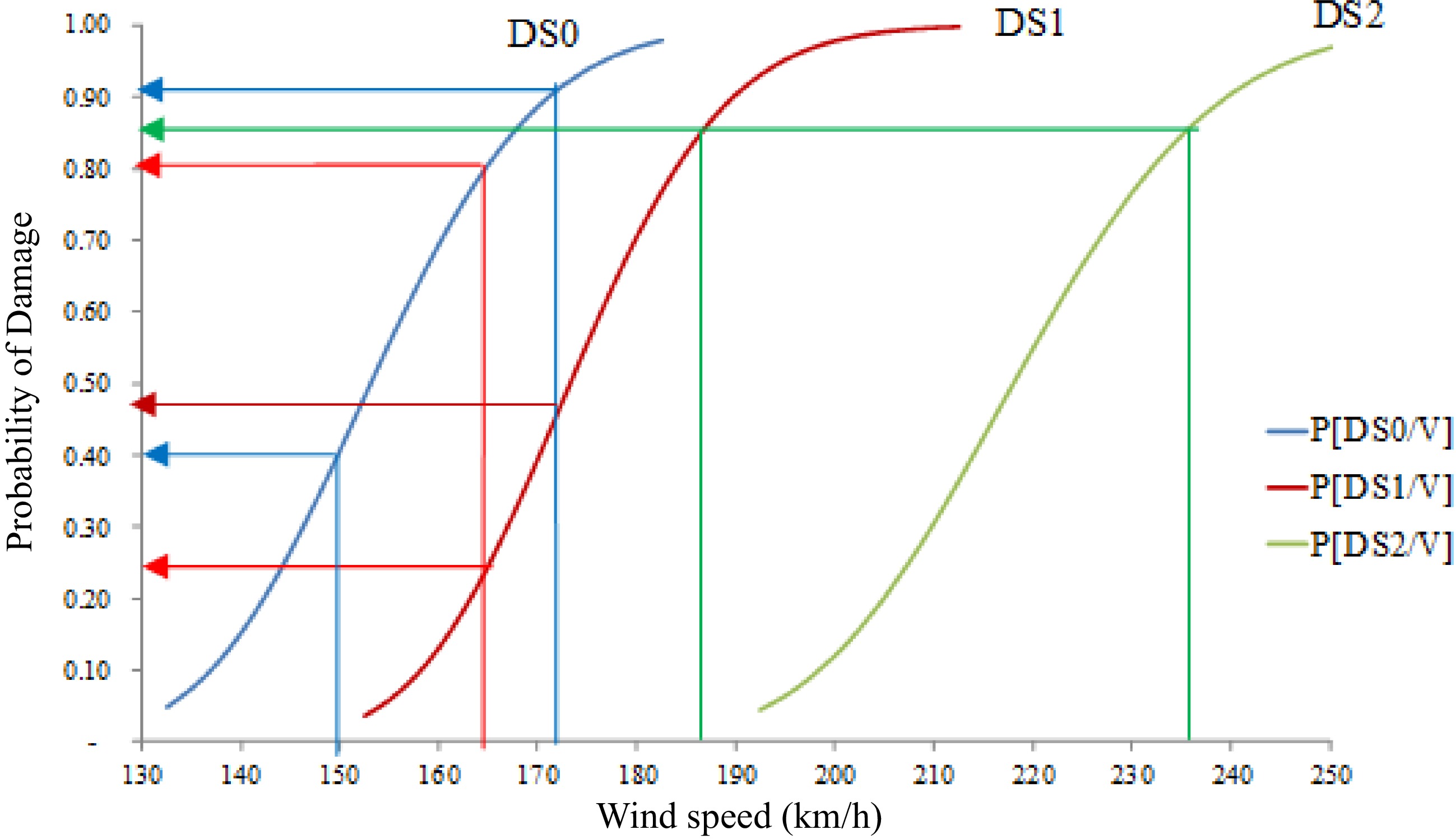
Figure 8.
Probability P[DSi/V] to reach damage levels DS1, DS2 and DS3 in tanks located in the Patagonia region of Argentina.
-
H
(m)Courses Thickness t (m) D = 35 m D = 40 m D = 45 m D = 50 m D = 55 m D = 60 m 12 V1 0.014 0.016 0.018 0.018 0.020 0.022 V2 0.012 0.012 0.014 0.016 0.016 0.018 V3 0.008 0.010 0.010 0.010 0.012 0.012 V4 0.006 0.008 0.008 0.008 0.008 0.008 14 V1 0.016 0.018 0.020 0.022 0.025 0.025 V2 0.014 0.014 0.016 0.018 0.020 0.020 V3 0.010 0.012 0.012 0.014 0.014 0.016 V4 0.008 0.008 0.008 0.010 0.010 0.010 V5 0.006 0.008 0.008 0.008 0.008 0.008 16 V1 0.018 0.020 0.022 0.025 0.028 0.028 V2 0.016 0.018 0.018 0.020 0.022 0.025 V3 0.012 0.014 0.016 0.016 0.018 0.020 V4 0.010 0.010 0.012 0.012 0.014 0.014 V5 0.006 0.008 0.008 0.008 0.008 0.010 V6 0.006 0.008 0.008 0.008 0.008 0.010 18 V1 0.020 0.022 0.025 0.028 0.030 0.032 V2 0.018 0.020 0.022 0.025 0.025 0.028 V3 0.014 0.016 0.018 0.020 0.020 0.022 V4 0.012 0.012 0.014 0.016 0.016 0.018 V5 0.008 0.010 0.010 0.010 0.012 0.012 V6 0.008 0.010 0.010 0.010 0.012 0.012 20 V1 0.022 0.025 0.028 0.030 0.032 0.035 V2 0.020 0.022 0.025 0.028 0.028 0.032 V3 0.016 0.018 0.020 0.022 0.025 0.028 V4 0.014 0.014 0.016 0.018 0.020 0.020 V5 0.010 0.012 0.012 0.014 0.014 0.016 V6 0.010 0.012 0.012 0.014 0.014 0.016 V7 0.010 0.012 0.012 0.014 0.014 0.016 Table 1.
Geometry and course thickness of 30 tanks considered in this work.
-
Damage states (DS) Description DS0 No damage DS1 Large deflections on the cylindrical shell DS2 Buckling of the cylindrical shell DS3 Large deflections on the stiffening ring Table 2.
Damage states under wind for open-top tanks with a wind girder.
-
H D ID DS0 DS1 DS2 DS3 H12 D35 1 137.76 162.06 194.82 336.02 D40 2 160.62 181.31 227.16 360.73 D45 3 153.32 174.19 216.82 374.04 D50 4 145.23 165.27 205.39 373.76 D55 5 152.76 180.83 216.03 374.75 D60 6 145.11 170.75 205.22 370.98 H14 D35 7 145.57 162.05 205.87 295.03 D40 8 148.55 166.20 210.08 311.24 D45 9 136.42 153.72 192.92 334.54 D50 10 155.36 177.51 219.71 339.86 D55 11 145.24 165.34 205.39 343,17 D60 12 141.89 167.26 200.67 338.77 H16 D35 13 131.32 161.94 185.71 262.20 D40 14 146.95 163.99 207.82 277.08 D45 15 150.58 170.90 212.95 293.37 D50 16 138.97 161.05 196.54 303.62 D55 17 138.51 174.17 195.88 313.97 D60 18 156.34 182.78 221.10 326.83 H18 D35 19 146.80 160.79 207.60 223.18 D40 20 159.01 177.71 224.87 243.63 D45 21 157.10 179.51 222.17 265.32 D50 22 152.54 172.17 215.72 293.32 D55 23 164.93 188.10 233.25 305.94 D60 24 163.69 180.32 231.49 315.63 H20 D35 25 163.64 199.59 231.42 195.03 D40 26 171.24 195.14 242.18 216.47 D45 27 171.58 203.68 242.64 293.32 D50 28 182.46 209.43 258.03 259.41 D55 29 178.95 208.23 253.07 272.48 D60 30 174.47 196.11 246.74 290.86 Table 3.
Wind speed for each tank considered reaching a damage level.
-
ID DS0 DS1 DS2 DS3 11 145.2 165.3 205.4 343.2 6 145.1 170.7 205.2 371.0 3 153.3 174.2 216.8 374.0 9 136.4 153.7 192.9 334.5 28 182.5 209.4 258.0 259.4 22 152.5 172.2 215.7 293.3 13 131.3 161.9 185.7 262.2 19 146.8 160.8 207.6 223.2 3 153.3 174.2 216.8 374.0 12 141.9 167.3 200.7 338.8 30 174.5 196.1 246.7 290.9 23 164.9 188.1 233.2 305.9 2 160.6 181.3 227.2 360.7 17 138.5 174.2 195.9 314.0 11 145.2 165.3 205.4 343.2 Table 4.
Random tank selection for V = 165 km/h, assuming wind interval [162.5 km/h, 167.5 km/h].
-
DS0 DS1 DS2 DS3 1 1 0 0 1 0 0 0 1 0 0 0 1 1 0 0 0 0 0 0 1 0 0 0 1 1 0 0 1 1 0 0 1 0 0 0 1 1 0 0 0 0 0 0 1 0 0 0 1 0 0 0 1 0 0 0 1 1 0 0 Total 13 6 0 0 hi 0.87 0.4 0 0 Table 5.
Damage matrix for random tank selection (V = 165 km/h), assuming wind interval [162.5 km/h, 167.5 km/h].
-
V inf
(km/h)V m
(km/h)V sup
(km/h)Ln
(Vm)fi Fi hi Hi 127.5 130 132.5 4.87 0 0 0.000 0 132.5 135 137.5 4.91 2 2 0.133 0.133 137.5 140 142.5 4.94 1 3 0.067 0.200 142.5 145 147.5 4.98 3 6 0.200 0.400 147.5 150 152.5 5.01 1 7 0.067 0.467 152.5 155 157.5 5.04 4 11 0.267 0.733 157.5 160 162.5 5.08 0 11 0.000 0.733 162.5 165 167.5 5.11 2 13 0.133 0.867 167.5 170 172.5 5.14 0 13 0.000 0.867 172.5 175 177.5 5.16 0 13 0.000 0.867 177.5 180 182.5 5.19 2 15 0.133 1.000 Table 6.
Damage DS0: Wind speed intervals [km/h] shown on the left; logarithm of wind speed; and relative and absolute frequencies (shown on the right).
Figures
(8)
Tables
(6)