-
Figure 1.
Computational details and the coordinate system. (a) Flame structure in side view. (b) Disposition of the pyrolysis zone in top view.
-
Figure 2.
Computed and experimental profiles of soot volume fraction for ethylene flame at different locations x along the height z.
-
Figure 3.
Profiles of the surface temperature of (a)heptane and (b) dodecane as a function of time at U0 = 0.2 m/s.
-
Figure 4.
Spatial distribution of the computed pyrolysis rate over (a) heptane and (b) dodecane surfaces for the different times at U0 = 0.2 m/s.
-
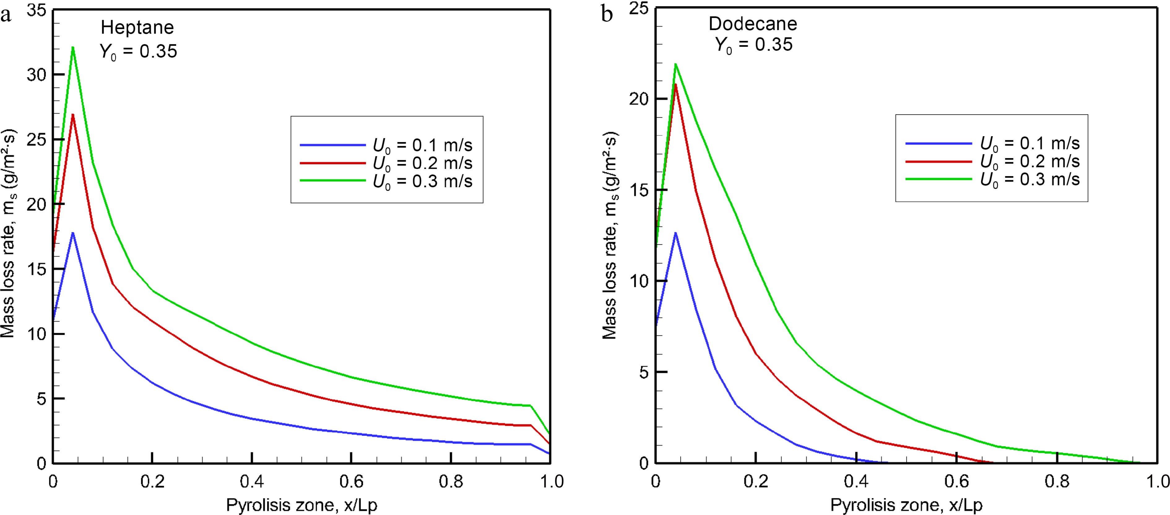
Figure 5.
Computed burning rates of (a) heptane and (b) dodecane at the steady mode as a function of oxidizer flow velocity.
-
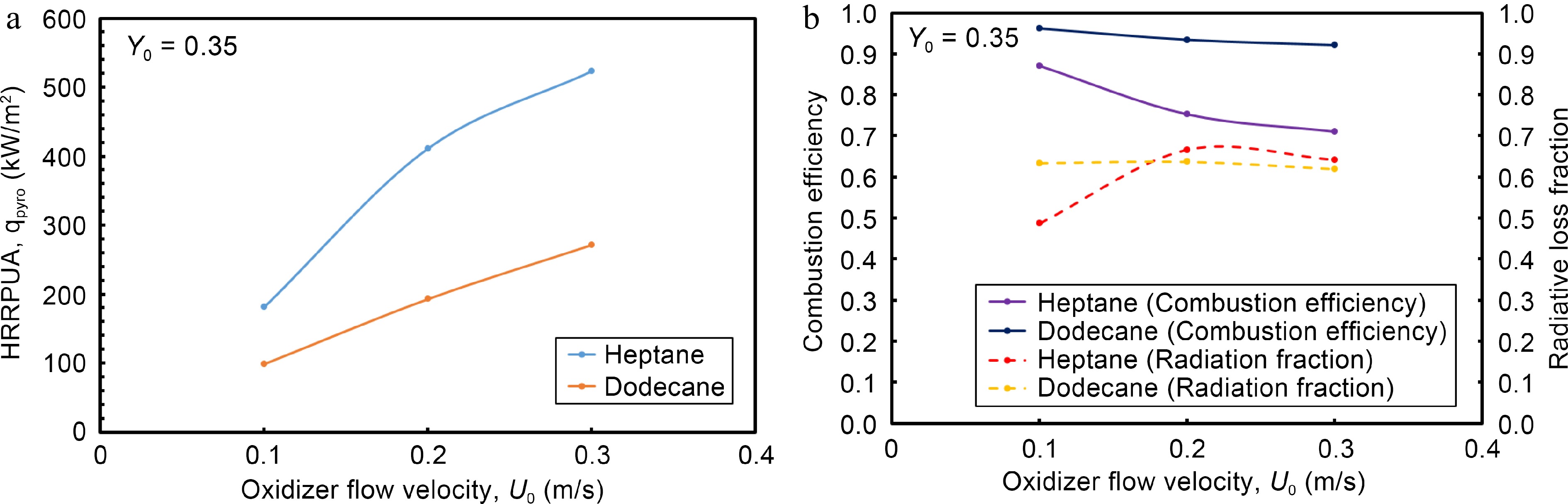
Figure 6.
Impact of oxidizer flow velocity on (a) HRRPUA, (b)combustion efficiency and radiation fraction at the steady mode.
-
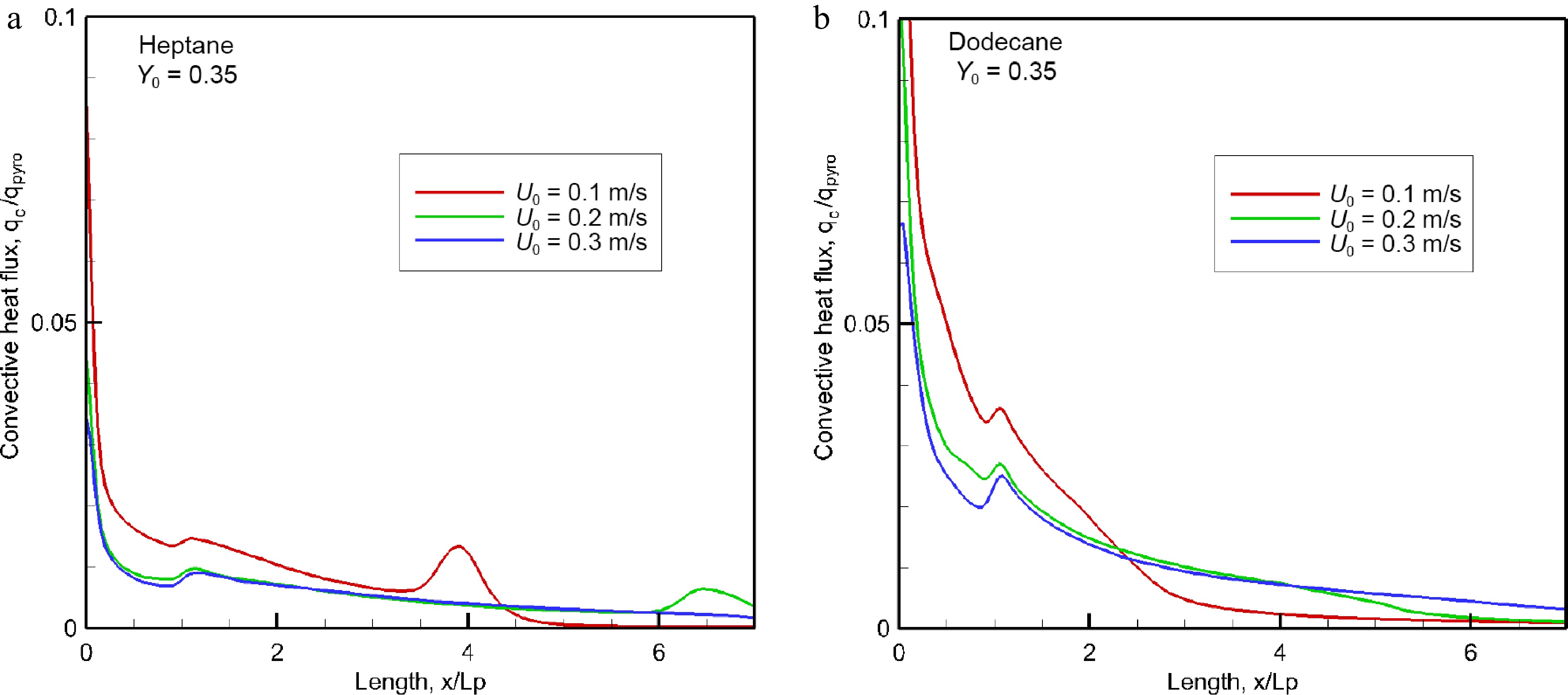
Figure 7.
Evolution of the convective fraction of HRRPUA over pyrolysis surface for different oxidizer flow velocity.
-
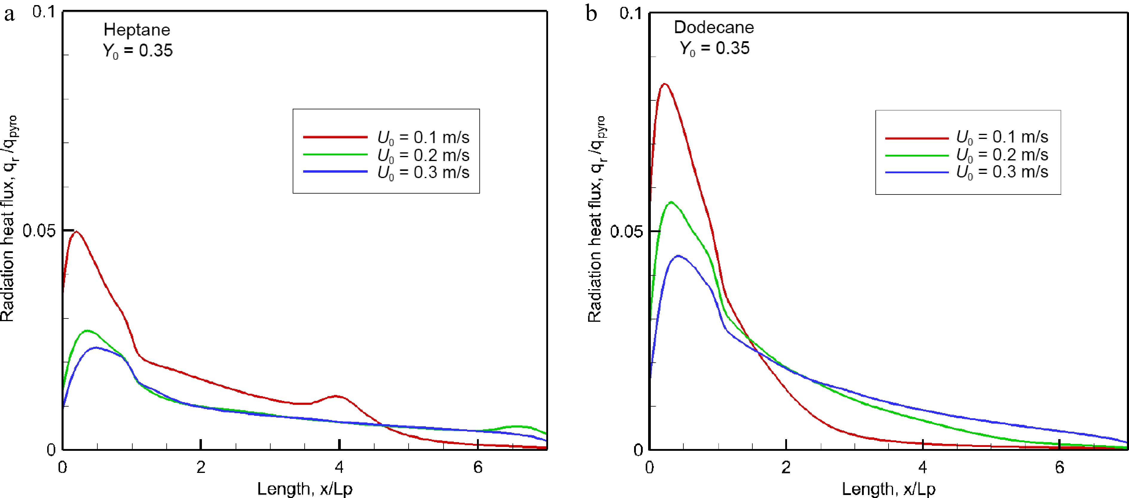
Figure 8.
Impact of oxidizer flow velocity on radiant heat flux over material surface at the steady mode.
-
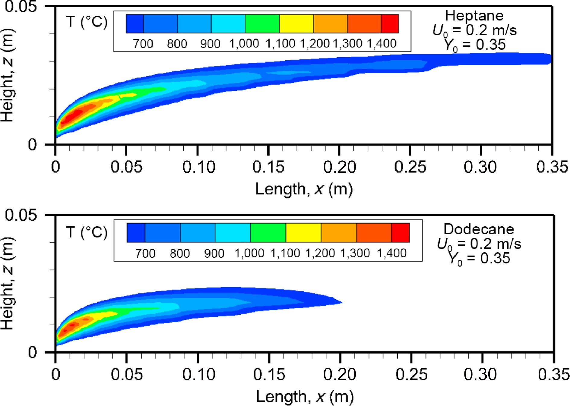
Figure 9.
Computed fields of gas temperature above 600 °C for heptane and dodecane at the steady mode (t = 10 s) at U0 = 0.2 m/s.
-
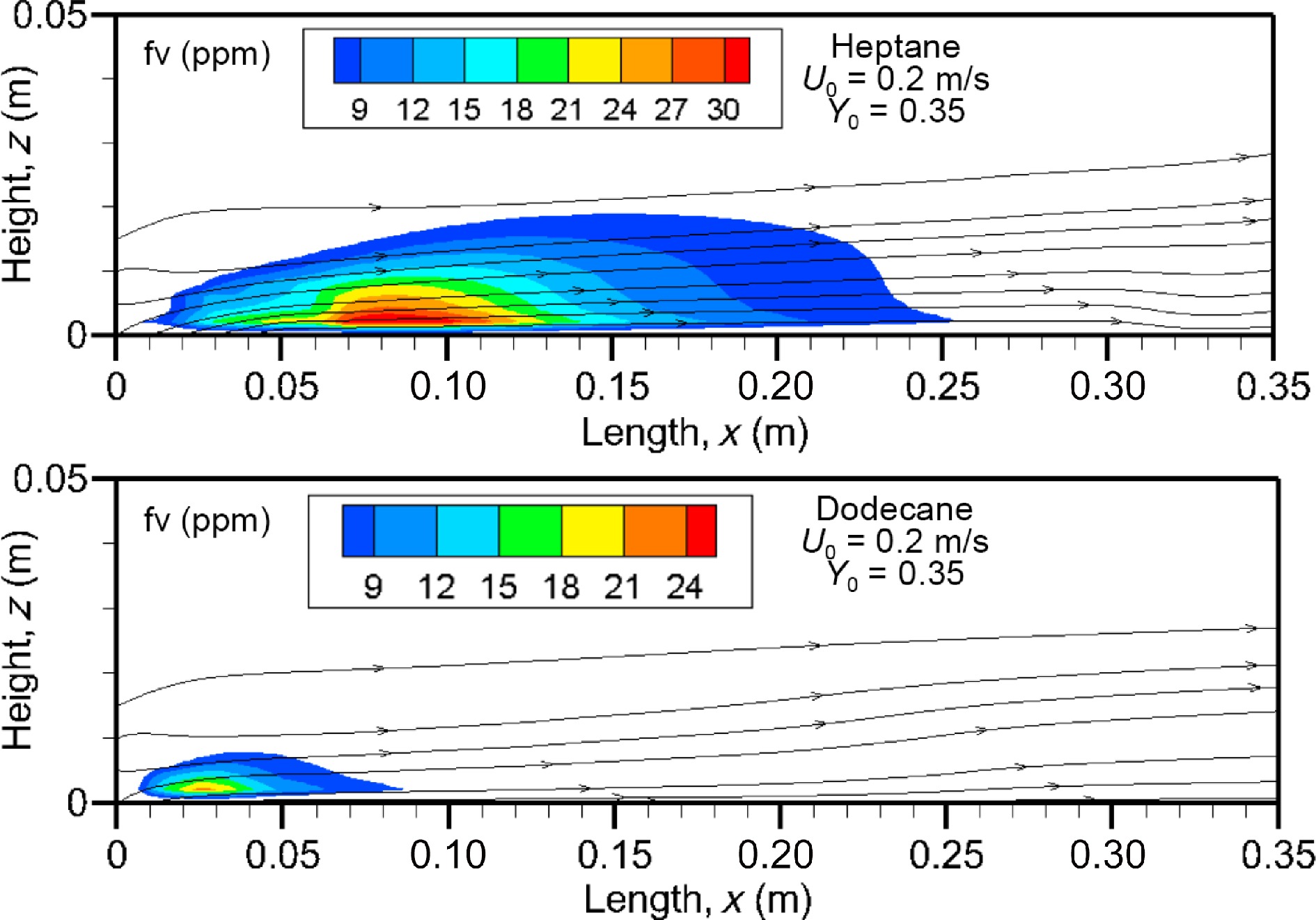
Figure 10.
Computed fields of soot volume fraction above 7 ppm on the axis of symmetry at U0 = 0.2 m/s.
-
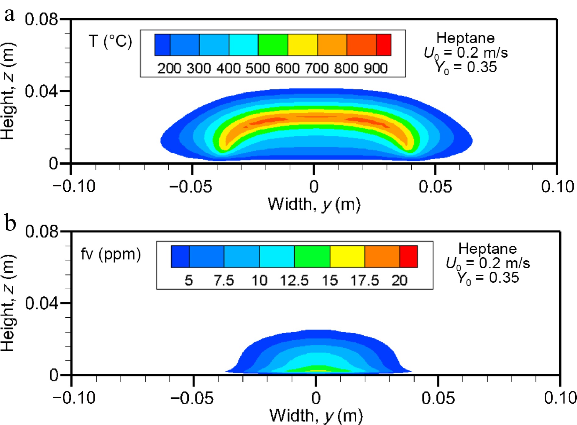
Figure 11.
Computed fields of (a) gas temperature and (b) soot volume fraction (above 2 ppm) on the cross-stream plane for heptane flame at x/Lp = 2 for U0 = 0.2 m/s.
-
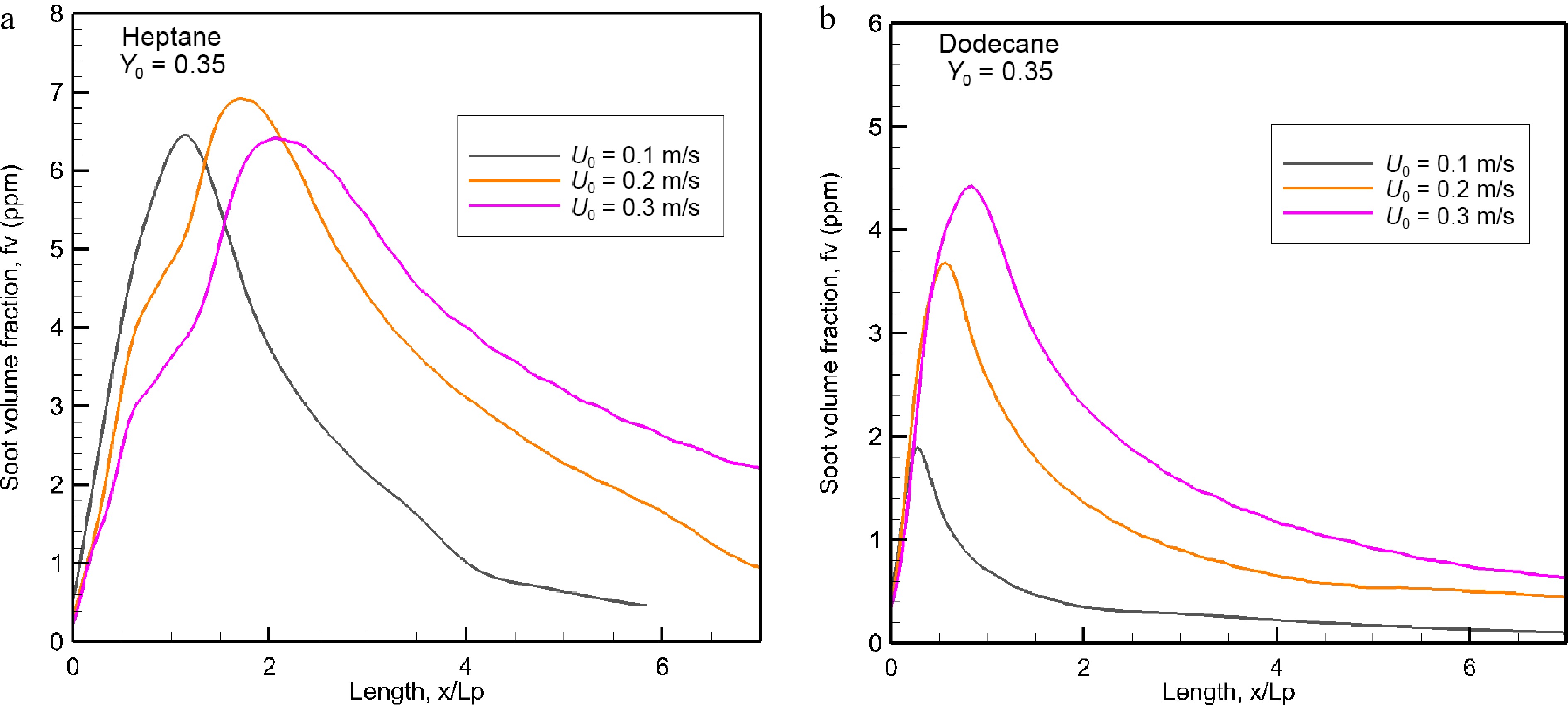
Figure 12.
Evolution of the mean value of soot volume fraction (ppm) in the windward direction as a function of oxidizer flow velocity.
-
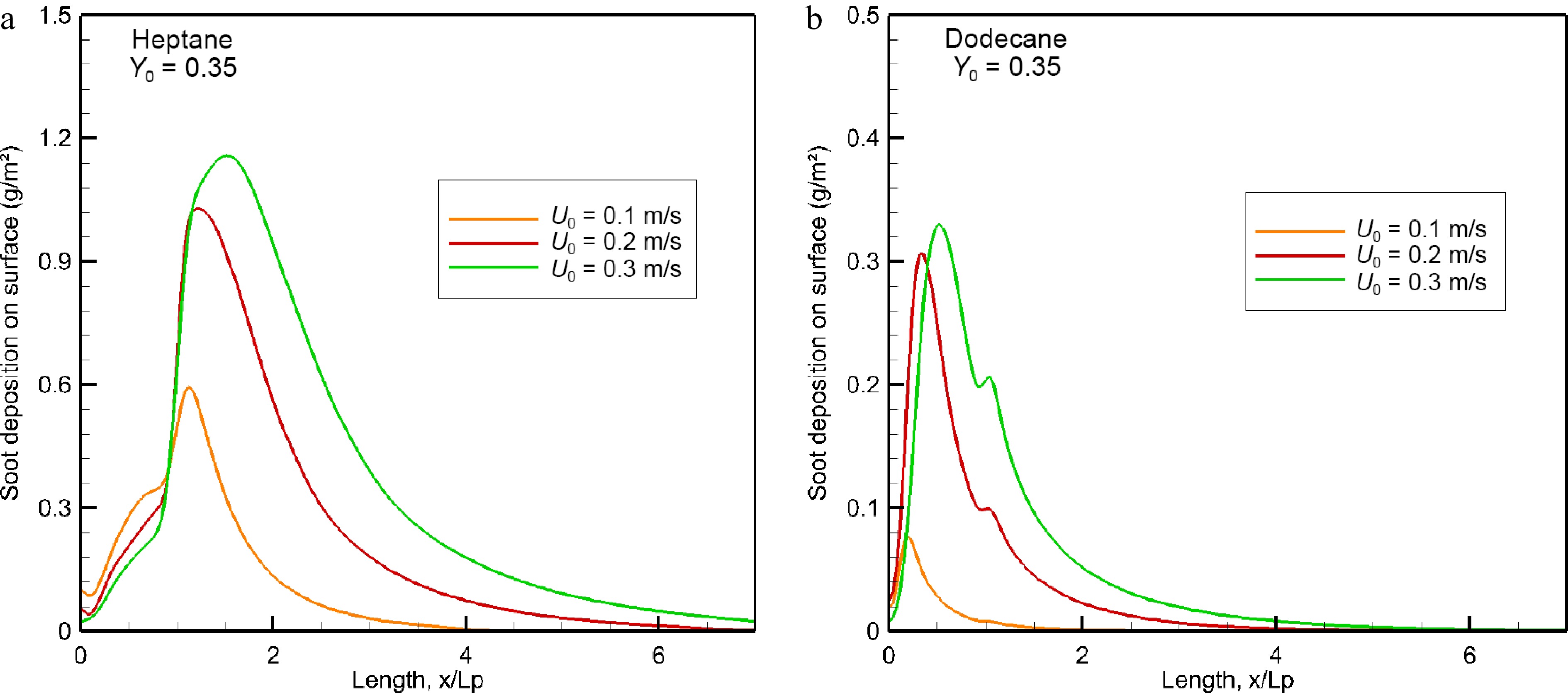
Figure 13.
Impact of oxidizer flow velocity on soot deposition (g/m2) over wall surface in the windward direction.
-
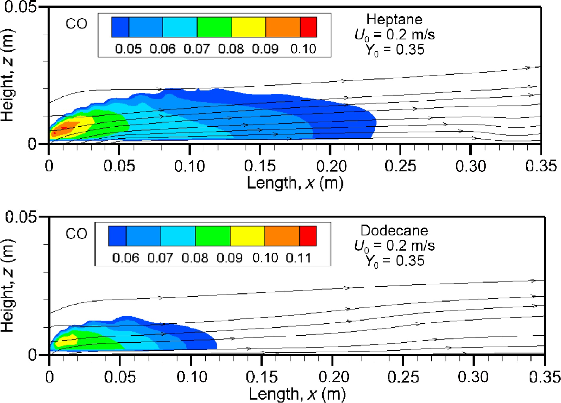
Figure 14.
Computed fields of CO volume fraction for heptane and dodecane flames at U0 = 0.2 m/s.
-
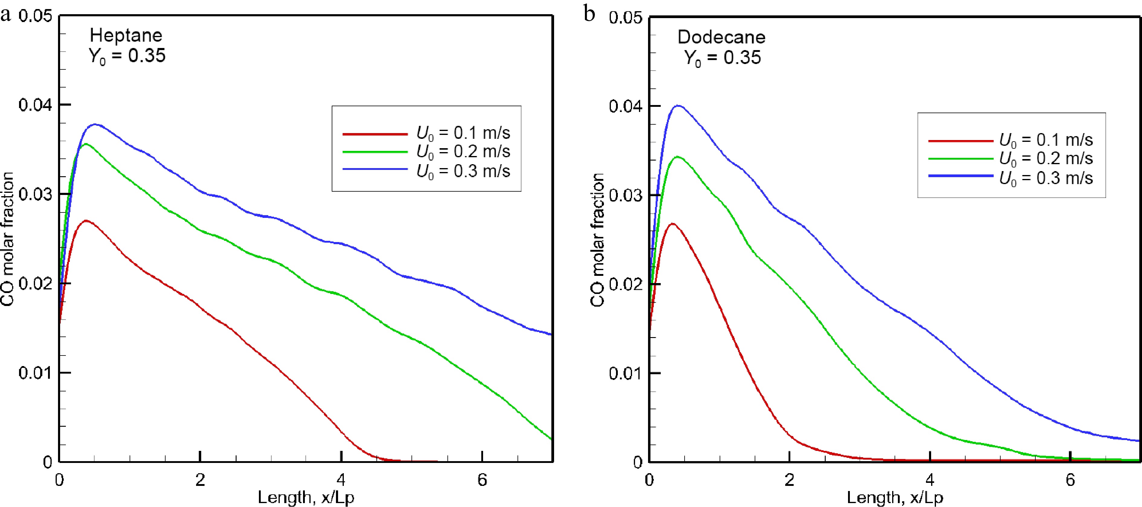
Figure 15.
Influence of oxidizer flow speed on the mean level of CO volume fraction in the forward direction.
-
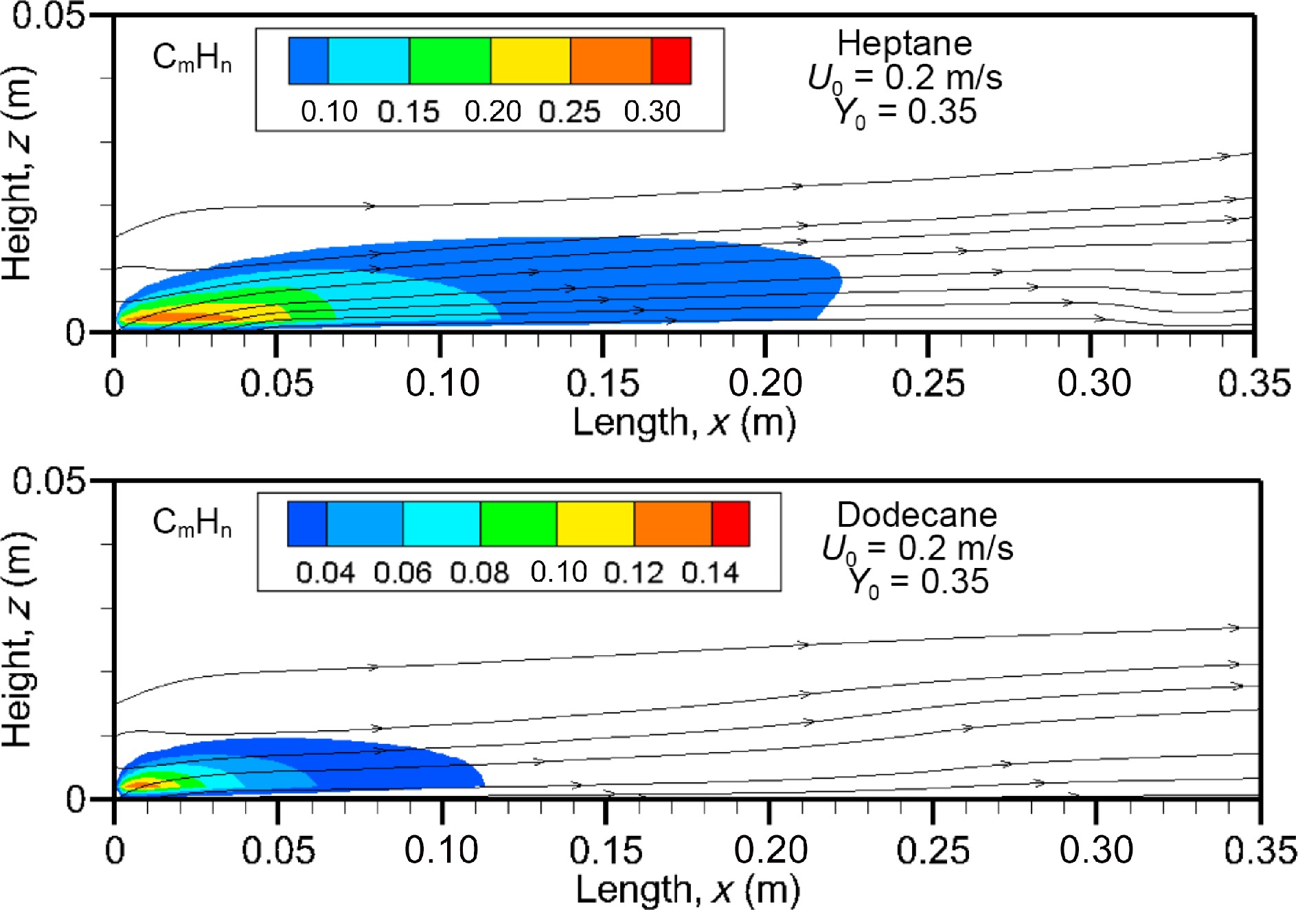
Figure 16.
Unburnt hydrocarbons field calculated at U0 = 0.2 m/s for heptane and dodecane flames.
-
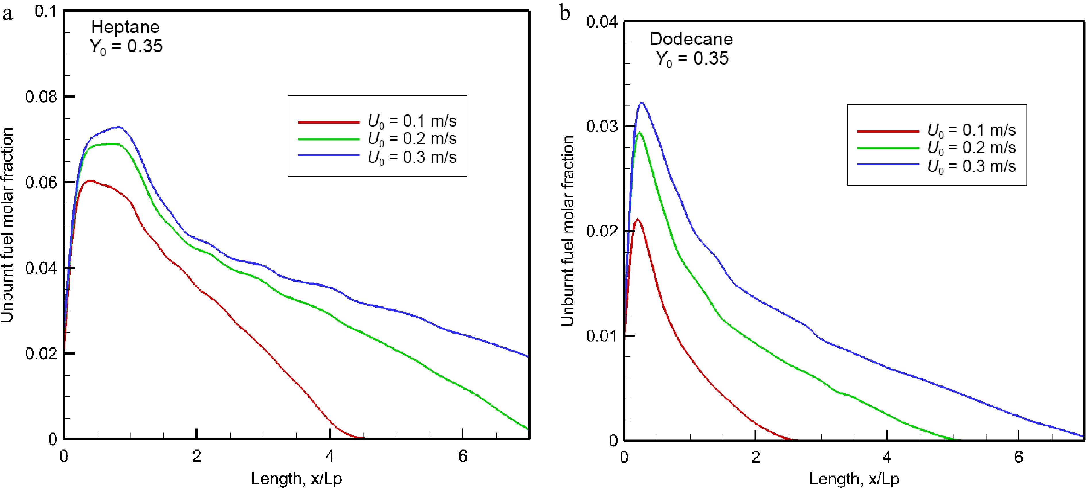
Figure 17.
Impact of oxidizer flow velocity on the mean concentration of unburnt hydrocarbons in the forward direction.
-
Fuel type LSP (m) Af Ethylene (C2H4) 0.106 4.1 × 10⁻⁵ Heptane (C7H16) 0.147 2.9 × 10⁻⁵ Dodecane (C12H26) 0.137 3.1 × 10⁻⁵ Table 1.
Summary of LSP height and pre-exponential factor, Af, for three types of fuel.
-
Property Heptane Dodecane Conductivity k (W/m·K) 0.17 0.14 Density ρ (kg/m3) 684 750 Heat capacity Cp (kJ/kg·K) 2.24 2.21 Pyrolysis heat, Lv (kJ/kg) 321 256 Heat of combustion, ΔHc (kJ/kg) 44500 44147 Boiling temperature Tb (°C) 98 216 Table 2.
Thermo-physical and combustion properties of heptane and dodecane.
Figures
(17)
Tables
(2)