-
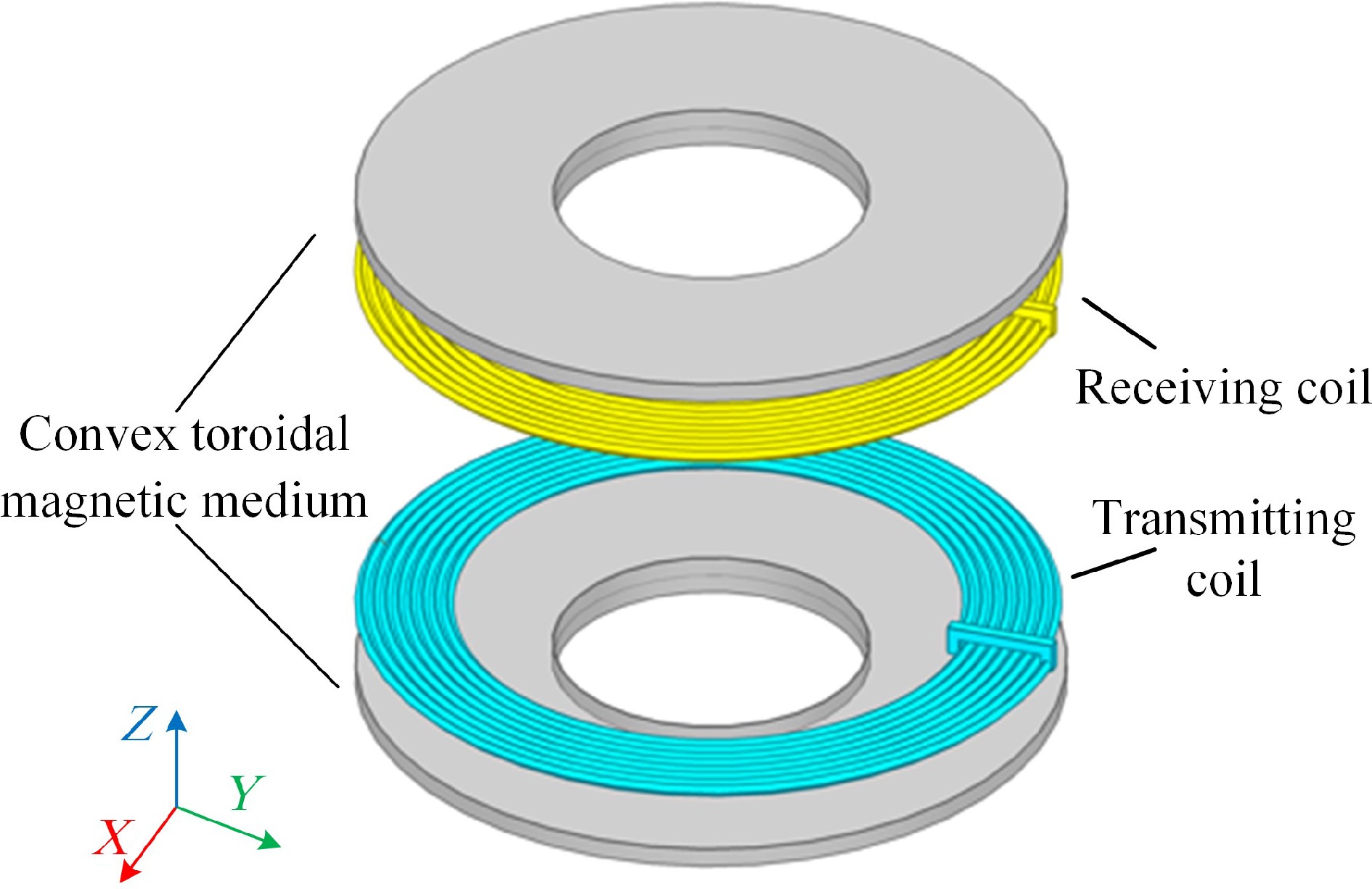
Figure 1.
Simulated model of bilateral convex toroidal magnetic media.
-
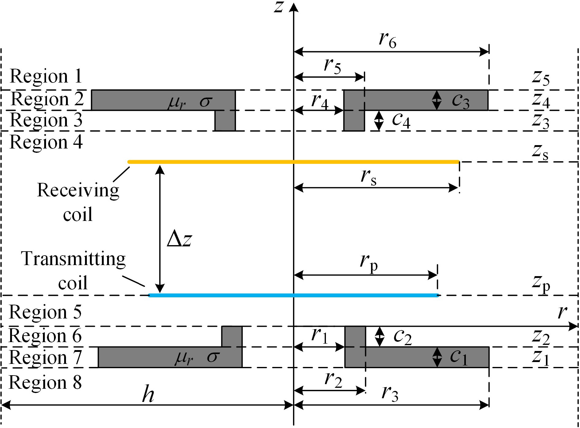
Figure 2.
Cross-sectional view of the model.
-
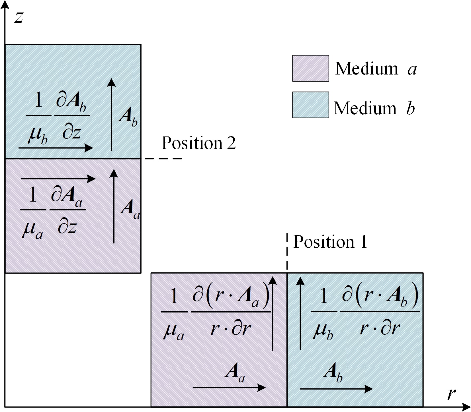
Figure 3.
Magnetic vector potential at interface in two positions.
-
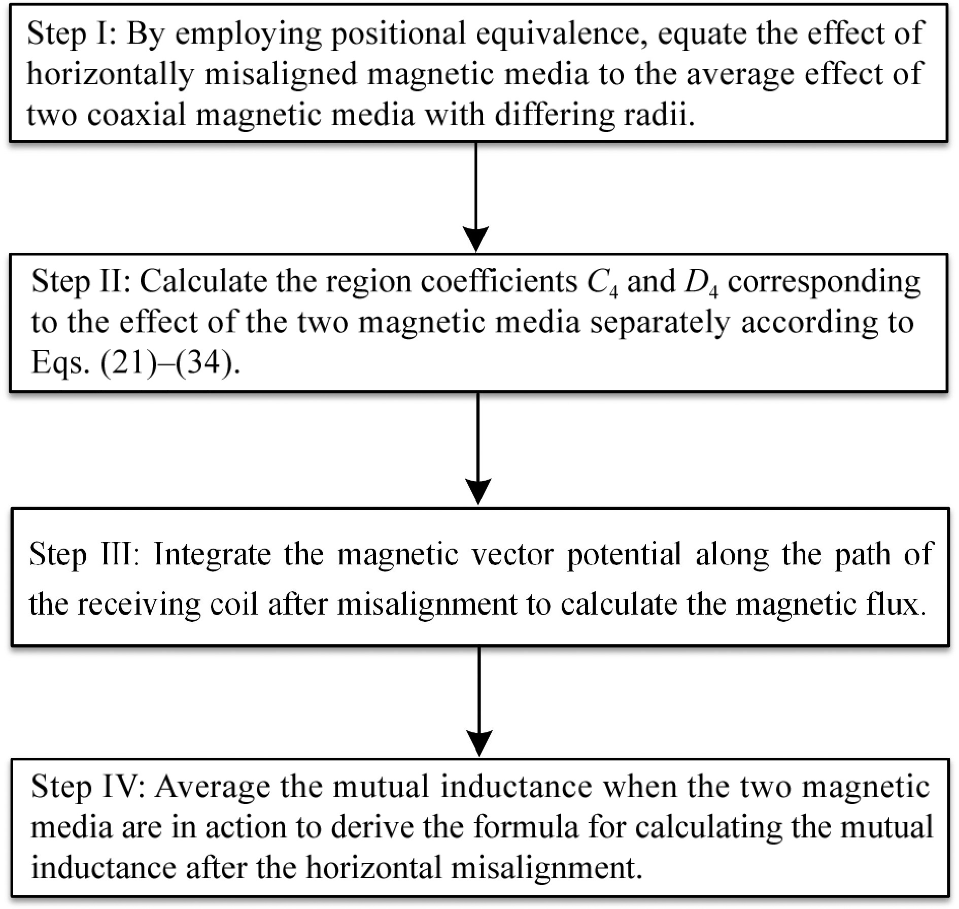
Figure 4.
Step-by-step calculation of mutual inductance with horizontal misalignment.
-
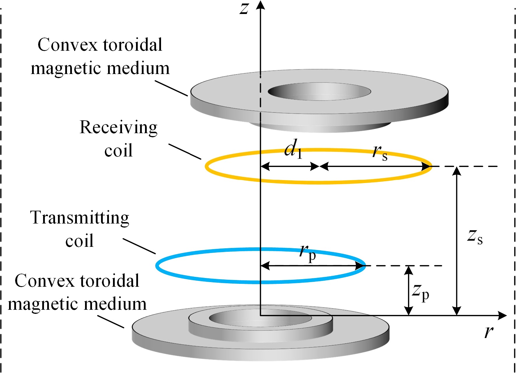
Figure 5.
Horizontal misalignment model diagram.
-
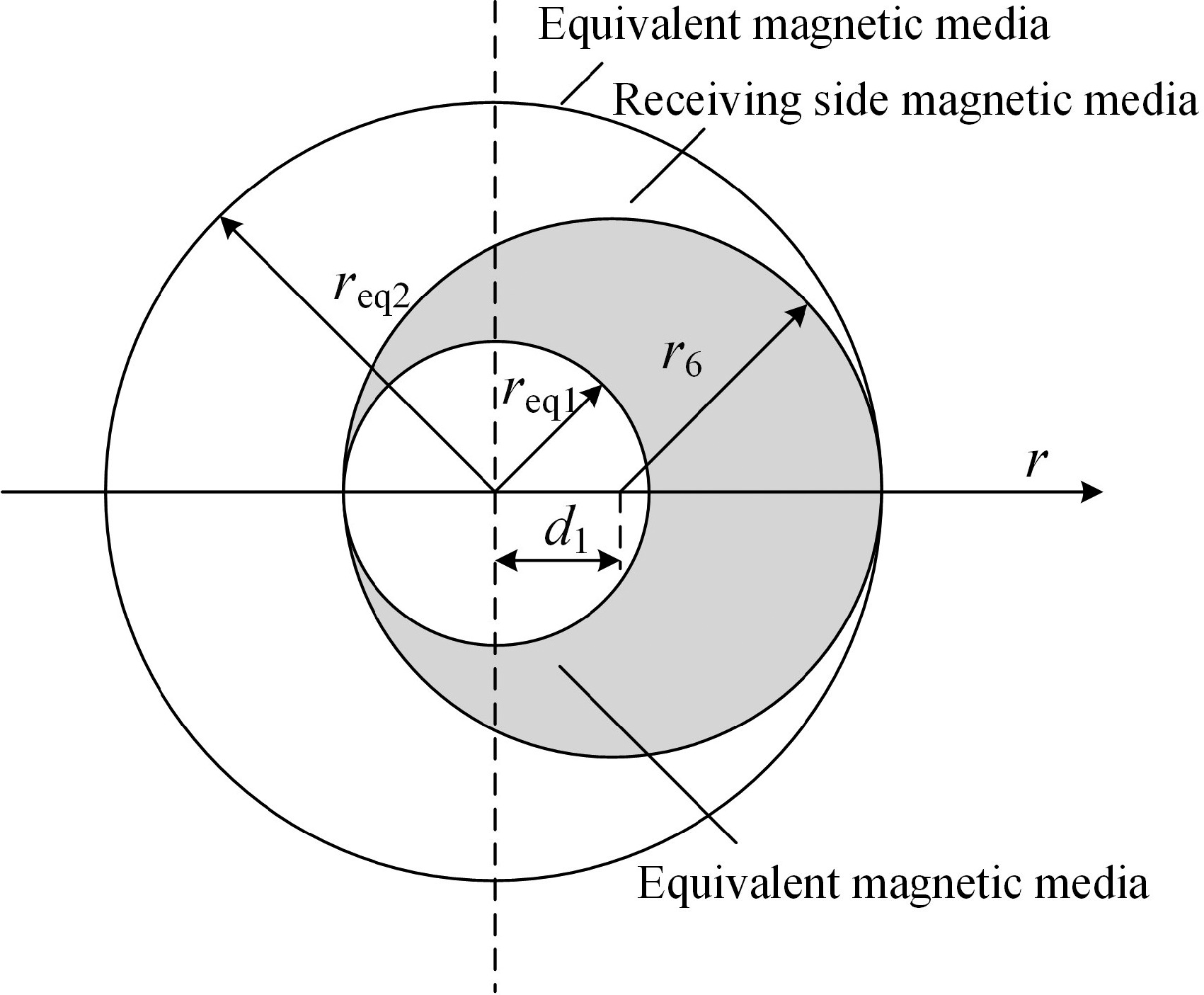
Figure 6.
Equivalent diagram of magnetic media positions.
-
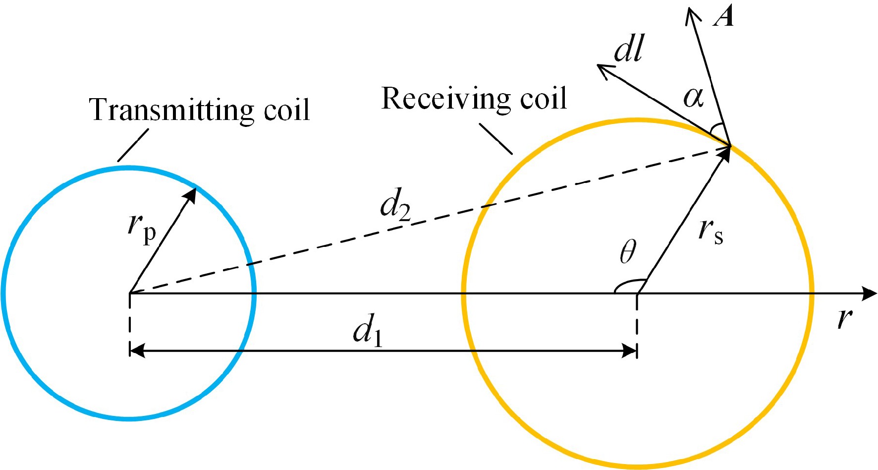
Figure 7.
Top view of coil with horizontal misalignment.
-
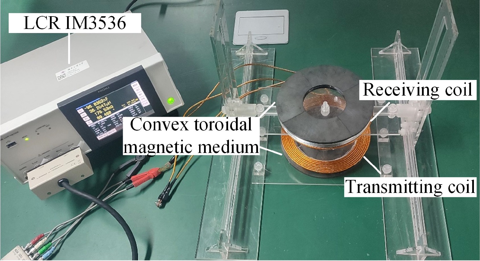
Figure 8.
Experimental test setup.
-
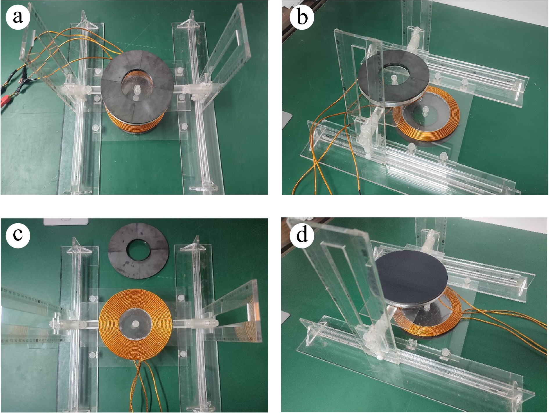
Figure 9.
Diagram of different experimental processes. (a) Transmission distance variation; (b) horizontal misalignment; (c) variation of turns; (d) disc-type comparison.
-

Figure 10.
Mutual inductance measurement schematic. (a) Series connection; (b) inverted series connection.
-
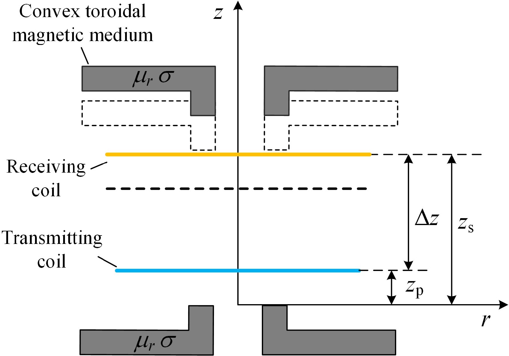
Figure 11.
Schematic of various transmission distances.
-
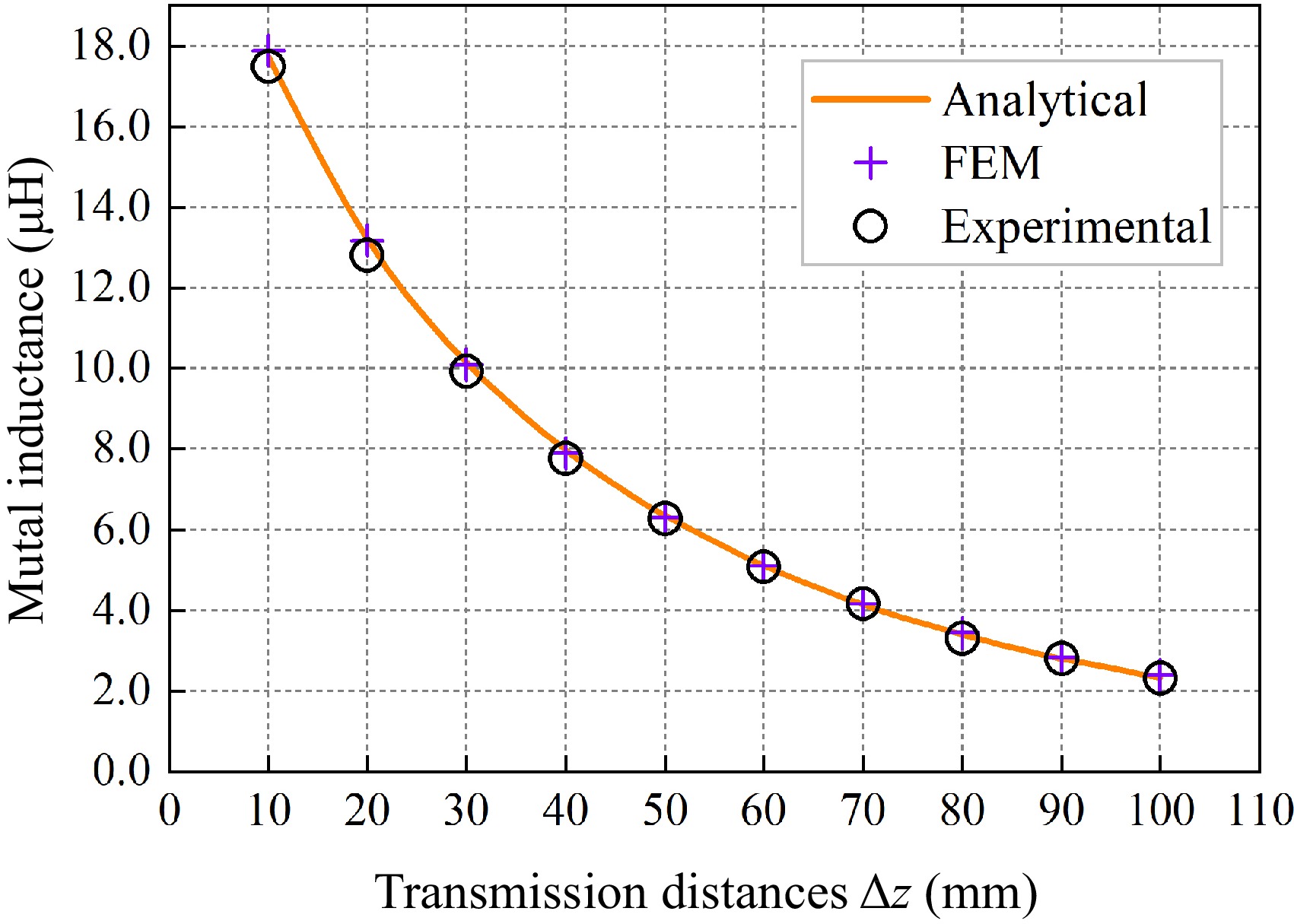
Figure 12.
Graph of inductance variation at different transmission distances.
-
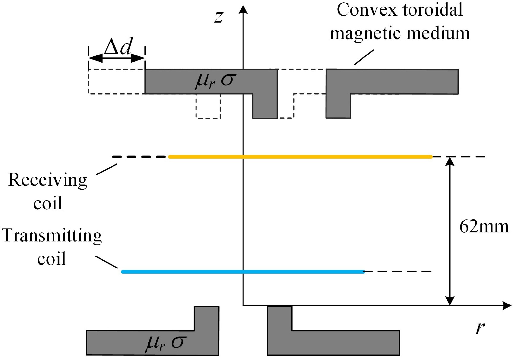
Figure 13.
Schematic diagram of horizontal misalignment.
-
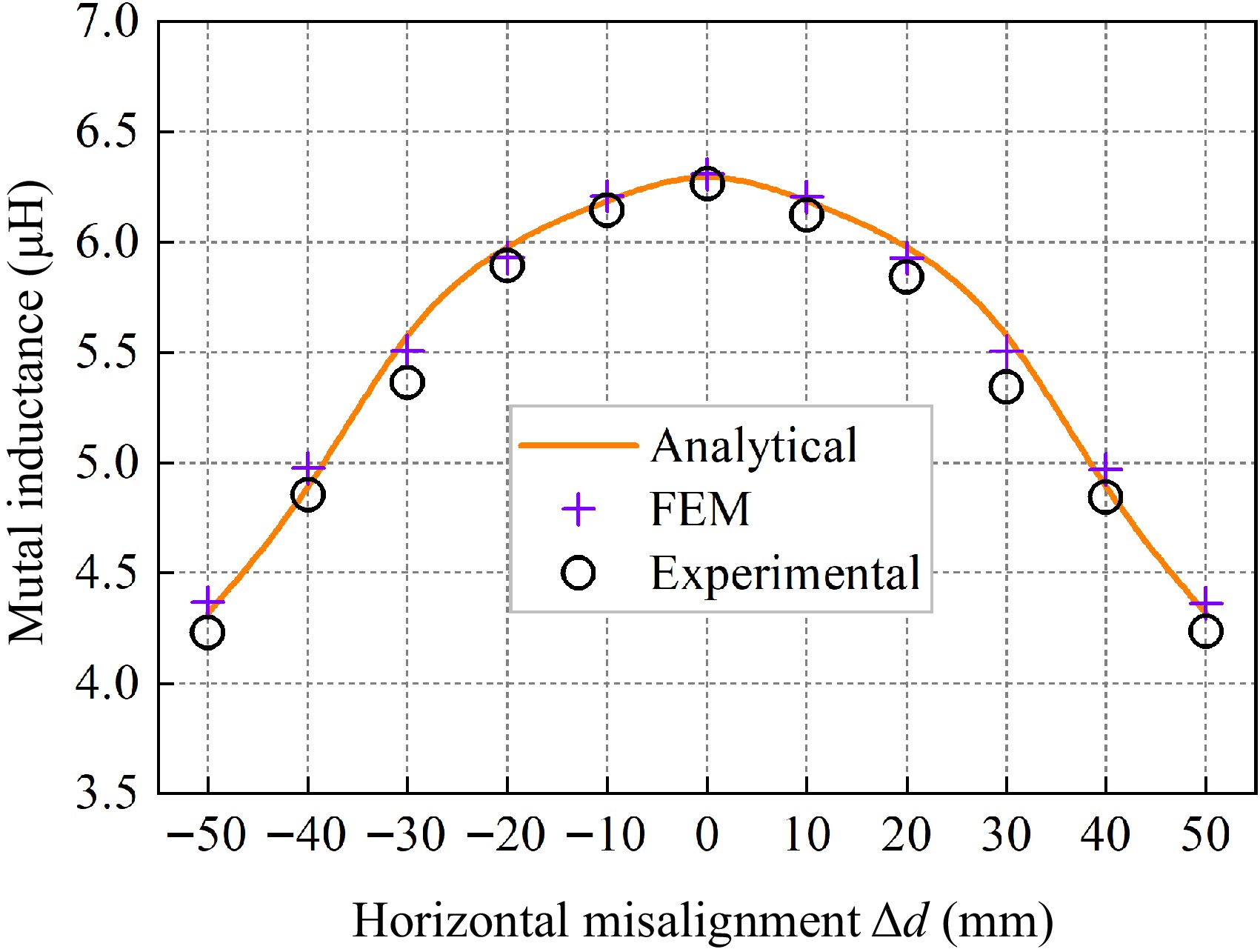
Figure 14.
Graph of inductance variation with different horizontal misalignment distances.
-
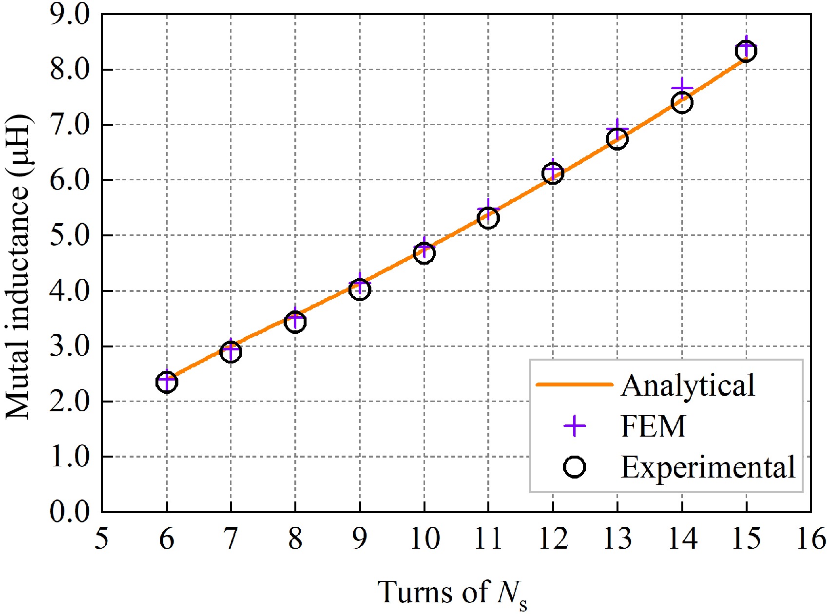
Figure 15.
Mutual inductance change with change in Ns.
-
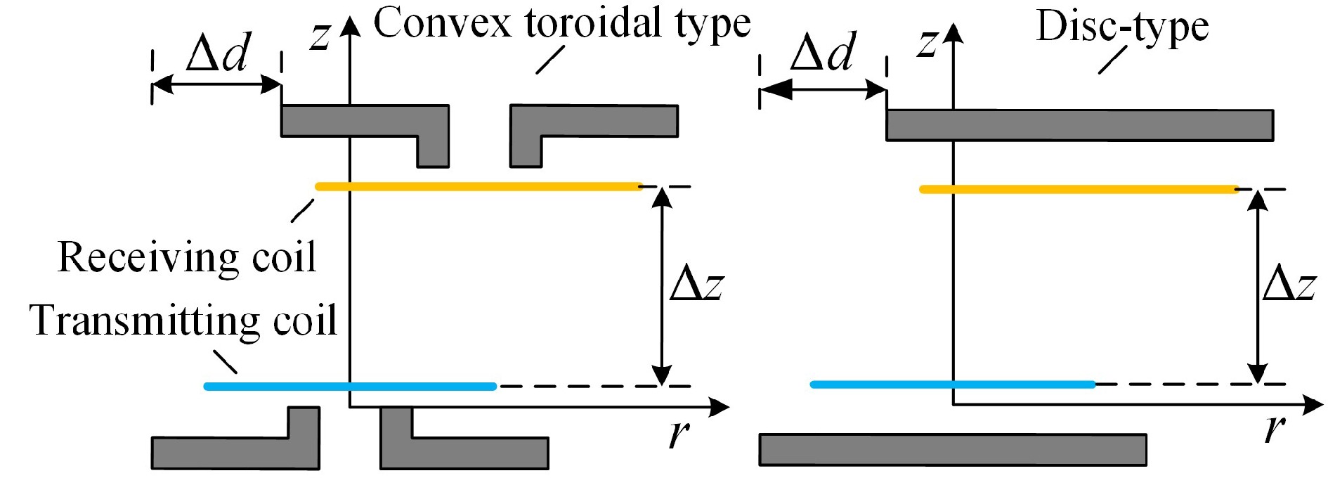
Figure 16.
Experimental conditions for two magnetic media structures.
-
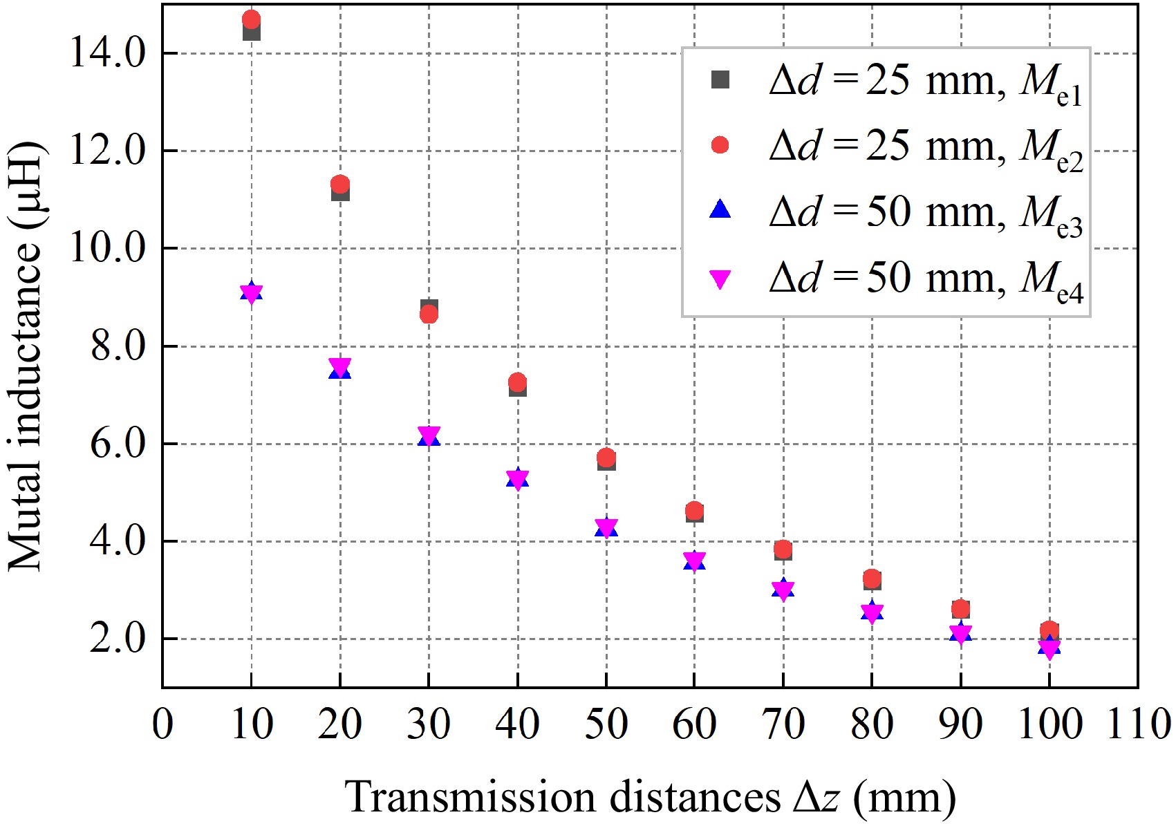
Figure 17.
Comparison of inductance between convex toroidal and disc-type magnetic media structures.
-
Parameters Value Coil radius change 0.1 mm Copper wire diameter 3 mm Height of receiving coil, zs 22−112 mm Coil to medium distance, zp 12 mm Turns of transmitting coil, Np 8 Turns of receiving coil, Ns 9 Transmitting coil inner radius, rp 62 mm Receiving coil inner radius, rs 65.1 mm Conductivity of mag. media, σ 0.01 S/m Relative permeability of mag. media, μr 2,800 Thickness of toroidal mag. media, c1 (c3) 5 mm Thickness of convex mag .media, c2 (c4) 5 mm Inner diameters of toroidal mag. media, r1 (r4) 35 mm Outer radius of toroidal mag. media, r3 (r6) 90 mm Outer radius of convex mag. media, r2 (r5) 35.15 mm Table 1.
Coil and magnetic media parameters.
-
Δz (mm) Ms (μH) Me (μH) Mc (μH) ɛ1 ɛ2 10 17.8868 17.4979 17.7292 0.89% 1.30% 20 13.1848 12.8047 13.2171 0.24% 3.12% 30 10.0934 9.9253 10.1615 0.67% 2.32% 40 7.9031 7.7624 7.9721 0.87% 2.63% 50 6.3084 6.2658 6.3461 0.59% 1.26% 60 5.0976 5.0777 5.1091 0.23% 0.61% 70 4.1553 4.1702 4.1515 0.09% 0.45% 80 3.4251 3.3106 3.4004 0.73% 2.64% 90 2.8461 2.7910 2.8050 1.47% 0.50% 100 2.3817 2.3080 2.3288 2.27% 0.89% Table 2.
Inductance values and errors at different transmission distances.
-
Δd (mm) Ms (μH) Me (μH) Mc (μH) ɛ1 ɛ2 −50 4.3656 4.2280 4.3171 1.12% 2.06% −40 4.9752 4.8559 4.8450 2.69% 0.23% −30 5.5096 5.4329 5.6536 2.55% 3.90% −20 5.9312 5.8920 6.0063 1.25% 1.90% −10 6.2088 6.1459 6.1930 0.26% 0.76% 0 6.3084 6.2658 6.3461 0.59% 1.26% 10 6.2060 6.1259 6.1930 0.21% 1.08% 20 5.9287 5.8404 6.0063 1.29% 2.76% 30 5.5065 5.4160 5.6536 2.60% 4.23% 40 4.9683 4.8462 4.8450 2.55% 0.03% 50 4.3630 4.2359 4.3171 1.06% 1.88% Table 3.
Inductance values and errors at horizontal misalignment.
-
Ns Ms (μH) Me (μH) Mc (μH) ɛ1 ɛ2 6 2.3982 2.3454 2.3927 0.23% 1.98% 7 2.9411 2.9163 3.0137 2.41% 3.23% 8 3.5225 3.4263 3.5554 0.93% 3.63% 9 4.1412 4.0136 4.1311 0.24% 2.85% 10 4.7921 4.6726 4.7387 1.13% 1.39% 11 5.4730 5.3113 5.3760 1.80% 1.20% 12 6.1956 6.1184 6.0401 2.57% 1.30% 13 6.9220 6.7356 6.7283 2.88% 0.11% 14 7.6679 7.4002 7.4462 2.98% 0.62% 15 8.4281 8.3281 8.1980 2.81% 1.59% Table 4.
Mutual inductance values and errors when changing the number of Ns.
-
Δz (mm) Δd = 25 mm Δd = 50 mm Me1 (μH) Me2(μH) γ Me1(μH) Me2(μH) γ 10 14.4329 14.6878 98.26% 9.0775 9.0925 99.84% 20 11.1521 11.31451 98.56% 7.4525 7.6125 97.90% 30 8.7612 8.6462 98.67% 6.0875 6.1975 98.23% 40 7.1582 7.2475 98.77% 5.2530 5.2925 99.25% 50 5.6380 5.7125 98.70% 4.2377 4.3170 98.16% 60 4.5627 4.6144 98.88% 3.5525 3.6344 97.75% 70 3.7967 3.8312 99.10% 2.9925 3.0250 98.93% 80 3.1946 3.2271 98.99% 2.5226 2.5558 98.70% 90 2.5934 2.6147 99.19% 2.1061 2.1232 99.19% 100 2.1293 2.1637 98.41% 1.8254 1.8325 99.61% Table 5.
Corresponding mutual inductance values and errors for two magnetic media structures.
-
Experiment type Algorithm time (s) Simulation time (s) Transmission distances 3.102 237.2 Horizontal misalignment 3.375 245.4 Adding one more coil 0.047 13.35 Table 6.
Calculating the average time required for mutual inductance.
-
Method DTD DHMD MM FMS DS MS ERR Ref. Elliptic integral √ √ × × × × / [12] Bessel integral √ √ × × × × / [13] Euler angles √ √ × × × × / [15] Fourier-Bessel transform √ √ √ × √ × / [17] Coordinate transformation method √ √ √ √ × × 4.78% [18] Truncation domain division √ √ √ √ × × 4.76% [20] Magnetic circuit magnetic resistance theory √ × √ √ √ × 8.13% [21] Magnetic vector potential position equivalence method √ √ √ √ √ √ 4.23% This study DTD: different transmission distances; DHMD: different horizontal misalignment distances; MM: magnetic medium; FMS: finite magnetic medium; DS: double side; MS: Material Saving; ERR: Error. DS means the magnetic medium is bilateral case, MS means saving the magnetic medium material, ERR means the maximum calculation error. Table 7.
Comparison of mutual inductance calculation methods with other literature.
Figures
(17)
Tables
(7)