-
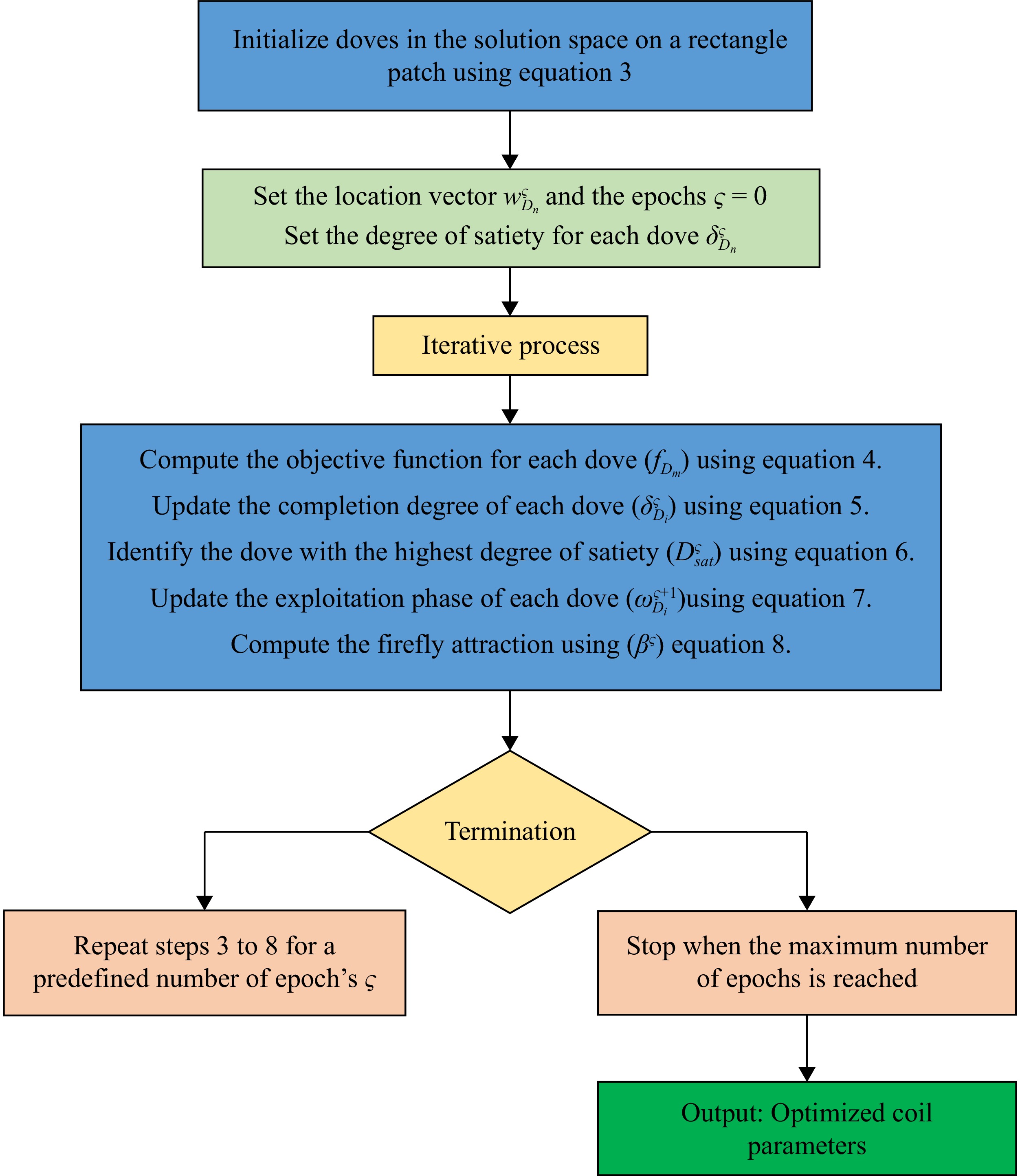
Figure 1.
Flowchart of the optimization algorithm.
-

Figure 2.
Circuit diagram of the Wireless Power Transfer (WPT) system.
-
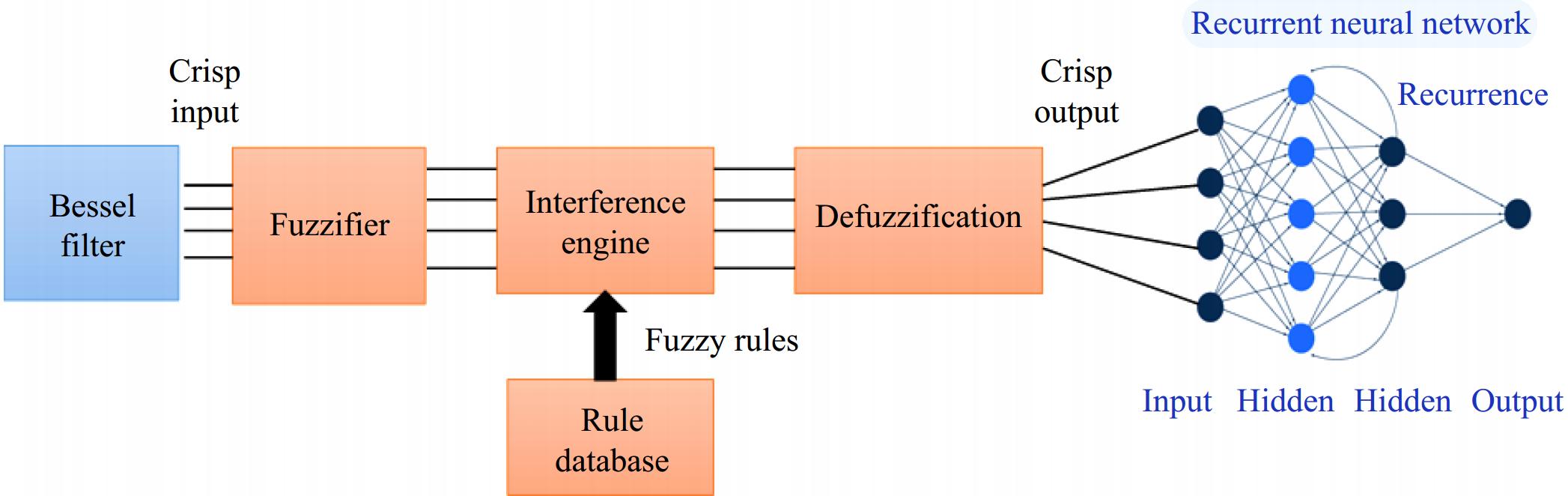
Figure 3.
Bessel Filter-based Fuzzy Recurrent Neural Network Control Architecture.
-
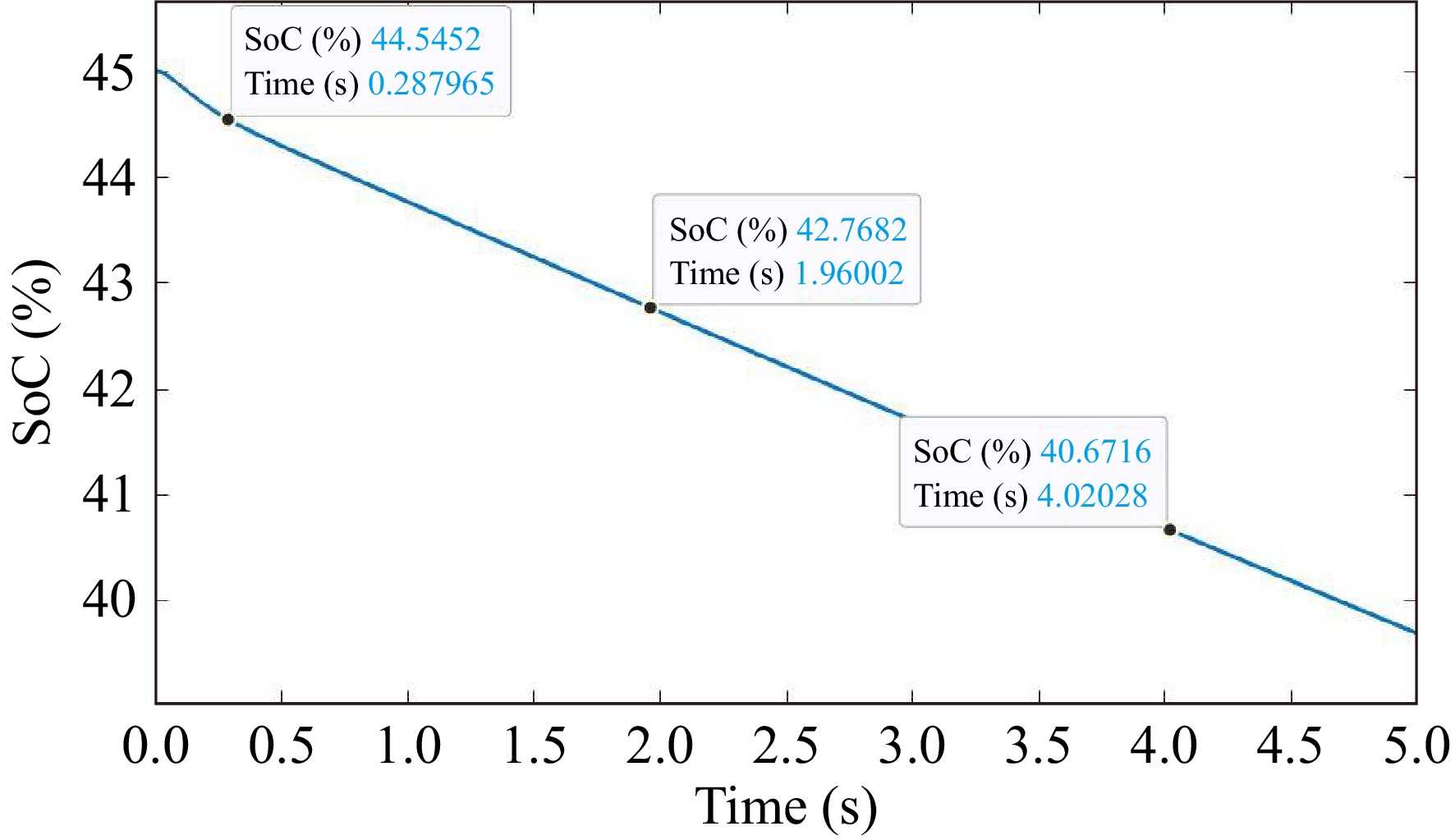
Figure 4.
The SoC of the proposed model.
-
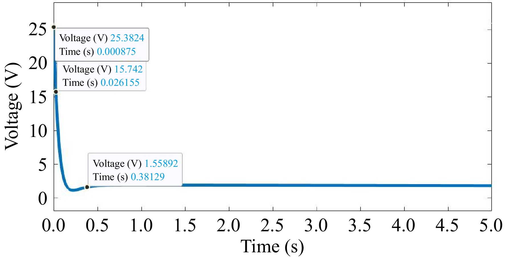
Figure 5.
Performance of voltage of the proposed model.
-
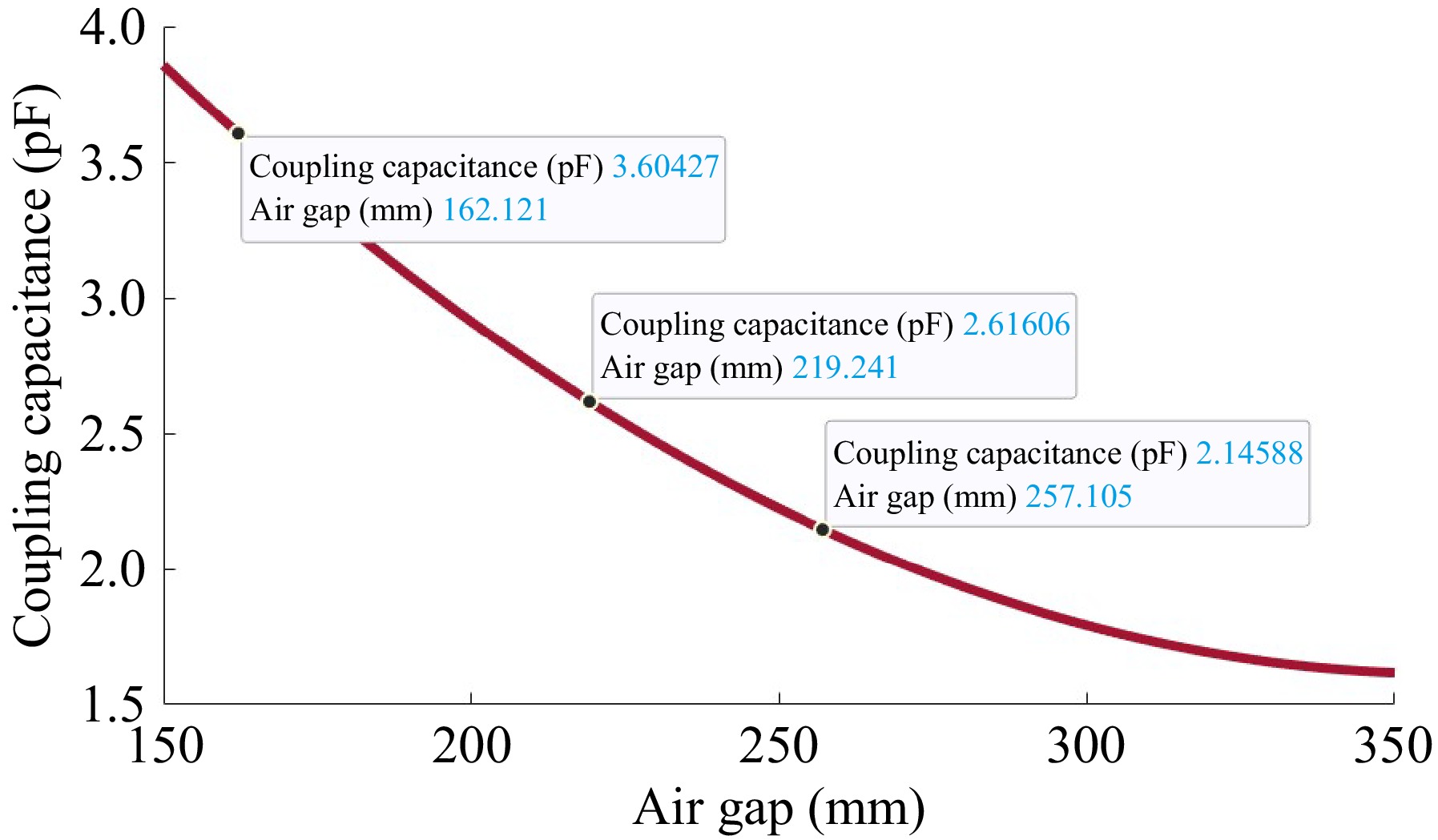
Figure 6.
Coupling capacitance of the proposed model.
-
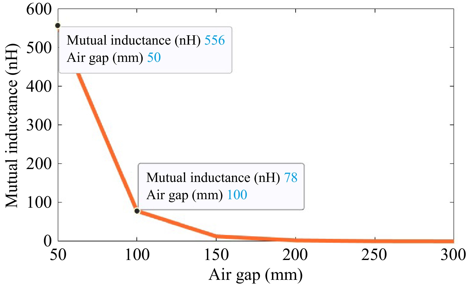
Figure 7.
Mutual inductance of the proposed model.
-
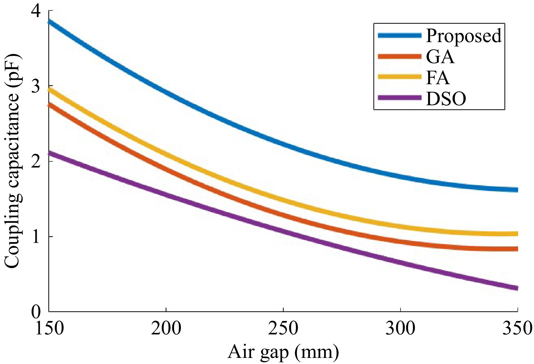
Figure 8.
Comparison of coupling capacitance.
-
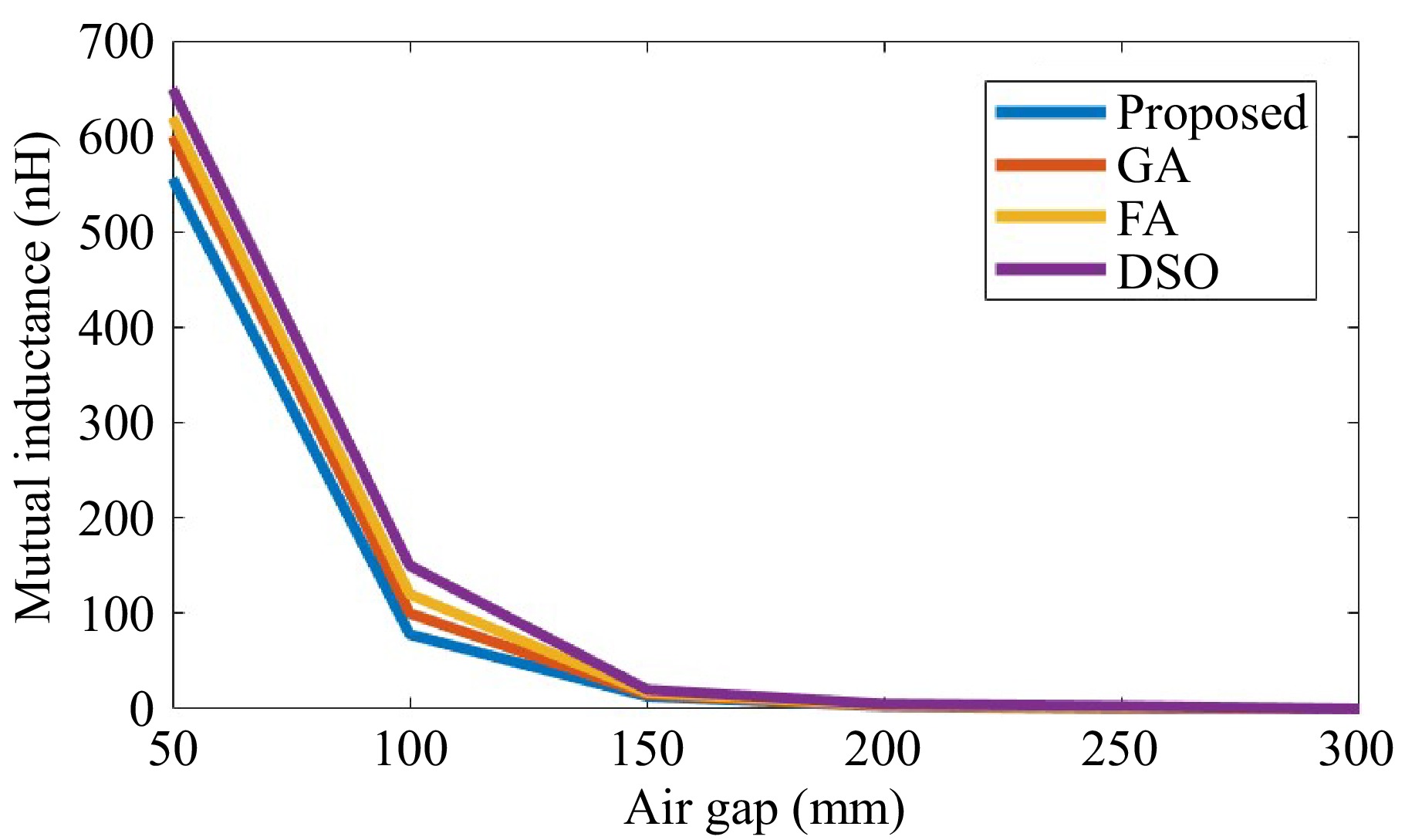
Figure 9.
Comparison of mutual inductance.
-
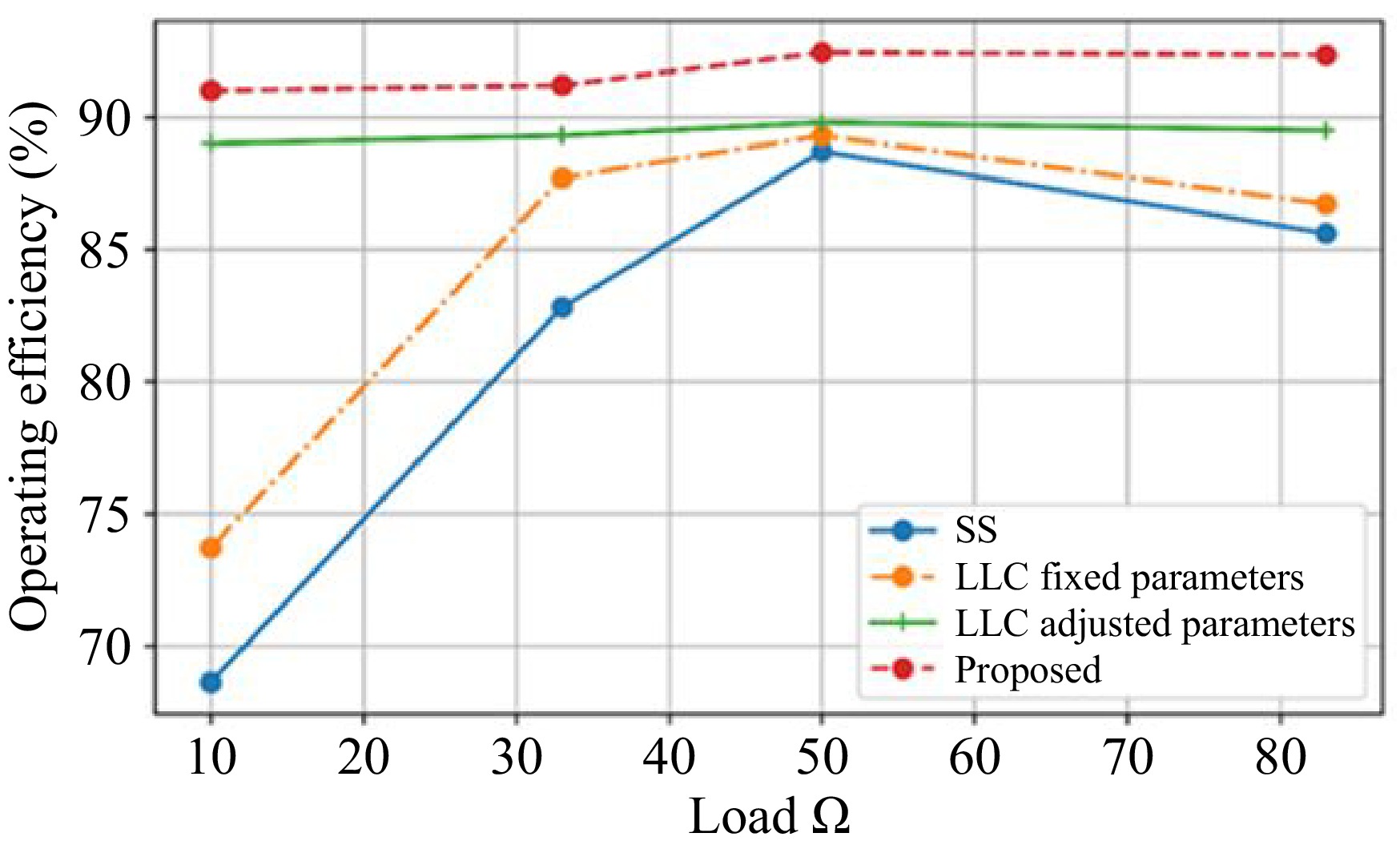
Figure 10.
Comparison of operating efficiency with various compensation.
-
Air gap
(mm)Coupling coefficient (k) Mutual inductance M (nH) GA FA DSO Proposed GA FA DSO Proposed 150 0.85 0.8 0.75 0.9 500 480 460 556 200 0.8 0.75 0.7 0.85 400 380 360 450 250 0.75 0.7 0.65 0.8 300 280 260 350 300 0.7 0.65 0.6 0.75 200 180 160 250 350 0.65 0.6 0.55 0.7 100 80 60 150 Table 1.
Comparison of the proposed method against GA, FA, and DSO methods for the coupling coefficient (k) and mutual inductance (M) at different air gaps.
-
Air gap
(mm)Number of turns Width of coil (mm) GA FA DSO Proposed GA FA DSO Proposed 150 18 17 16 20 2.5 2.2 2.1 2.0 200 20 19 18 22 2.6 2.3 2.2 2.2 250 22 21 20 24 2.7 2.4 2.3 2.4 300 24 23 22 26 2.8 2.5 2.4 2.6 350 26 25 24 28 2.9 2.6 2.5 2.8 Table 2.
Performance of the proposed method in terms of number of coil turns and coil width.
-
Air gap
(mm)Inner diameter (mm) Outer diameter (mm) GA FA DSO Proposed GA FA DSO Proposed 150 14 13 12 15 24 23 22 25 200 15 14 13 16 25 24 23 26 250 16 15 14 17 26 25 24 27 300 17 16 15 18 27 26 25 28 350 18 17 16 19 28 27 26 29 Table 3.
Performance of the proposed method in terms of inner diameter and outer diameter.
-
Parameter Value Description Output battery voltage (V) 25 The constant battery voltage maintained by the system Input voltage (V) 32 The input voltage supplied to the transmitter coil Frequency (kHz) 85 Operating frequency of the WPT system Air gap (mm) 150−350 Distance varied between the transmitter and receiver coils Coil turns 16−28 Number of turns in the transmitter and receiver coils Coil width (mm) 2.0−2.8 Width of the coils Inner diameter (mm) 12−19 Inner diameter of the coils Outer diameter (mm) 22−29 Outer diameter of the coils Coupling coefficient (k) 0.55−0.9 Coupling coefficient between the coils Mutual inductance (M) (nH) 60−556 Mutual inductance between the coils Compensation topology LCC and Series-Series Type of compensation circuit used Controller Bessel filter-based FRNN Type of controller used SoC Range 35%−45% State of charge range during WPT operation Operating efficiency 91%−94% Efficiency of the WPT system at different loads Table 4.
Key parameters of the Wireless Power Transfer (WPT) system used in the simulation.
Figures
(10)
Tables
(4)