-
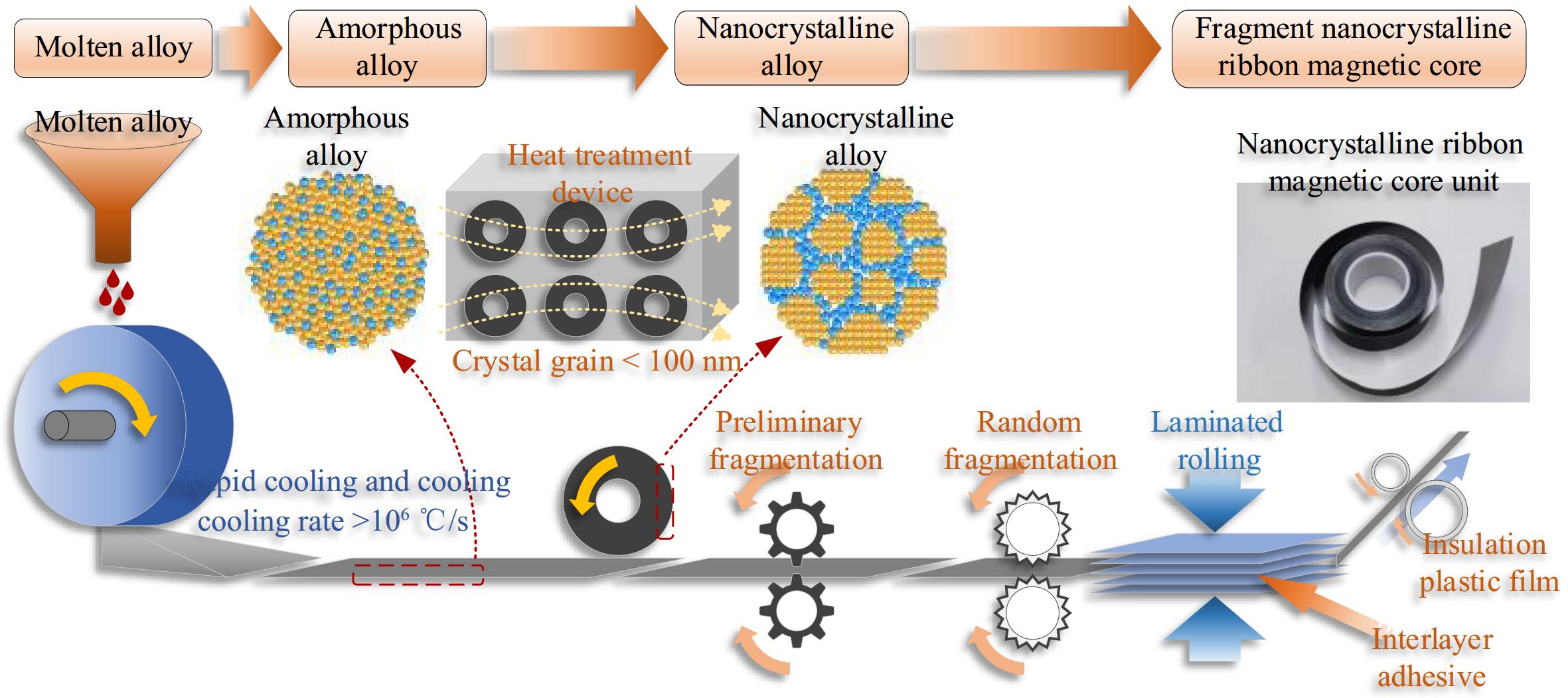
Figure 1.
Schematic diagram of the fragmentation process of nanocrystalline ribbon core.
-
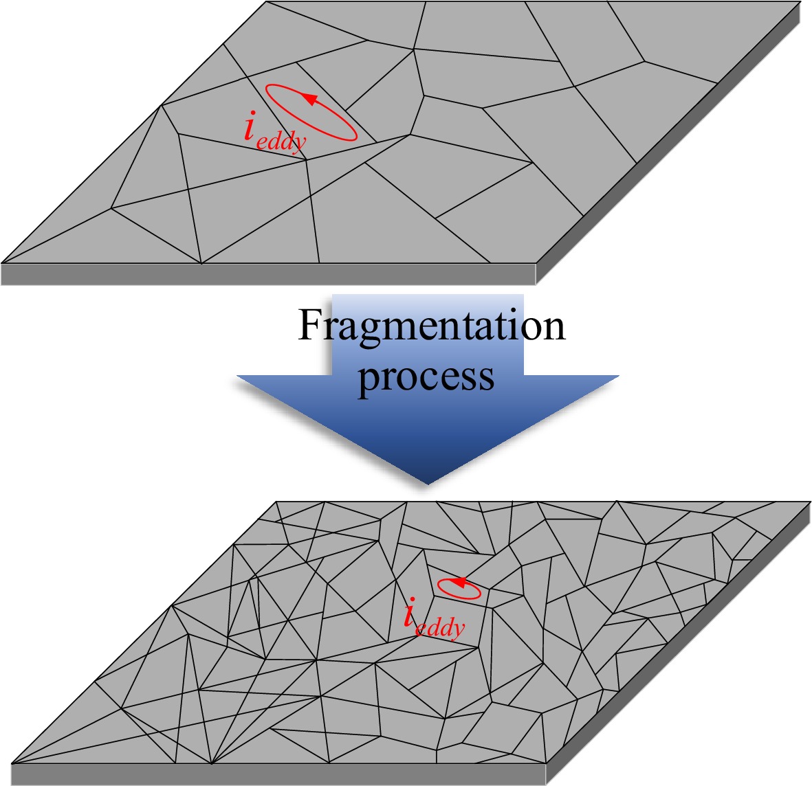
Figure 2.
Schematic diagram of the fragmentation process of nanocrystalline ribbon core.
-
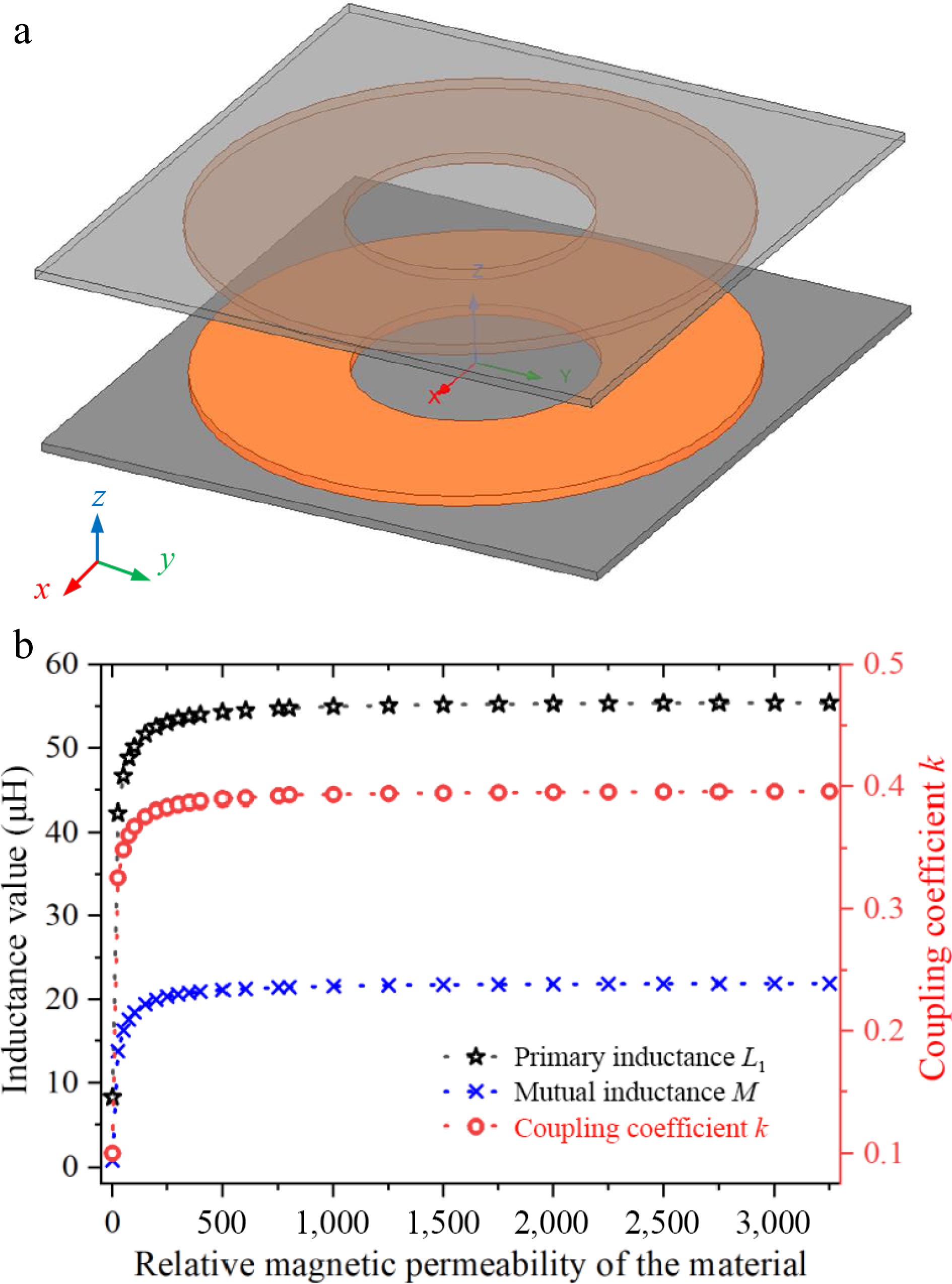
Figure 3.
Simulation results and simulation modeling of the relationship between inductance values, coupling coefficients and relative permeability of materials. (a) Maxwell finite element simulation model. (b) Relationship between inductance, coupling coefficient, and permeability.
-
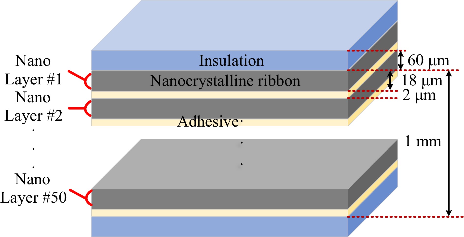
Figure 4.
Schematic diagram of 1 mm thickness laminated nanocrystalline magnetic core structure.
-
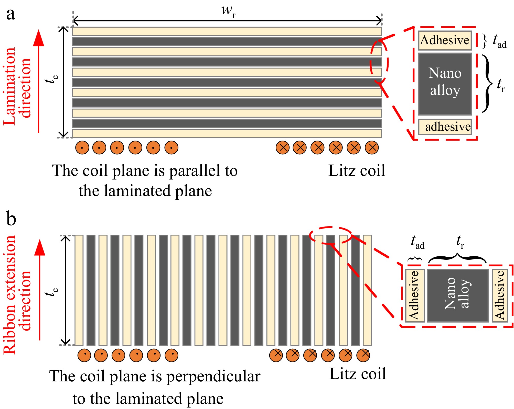
Figure 5.
Two typical lamination process approaches for nanocrystalline ribbons. (a) Flat laminated. (b) Longitudinal laminated.
-
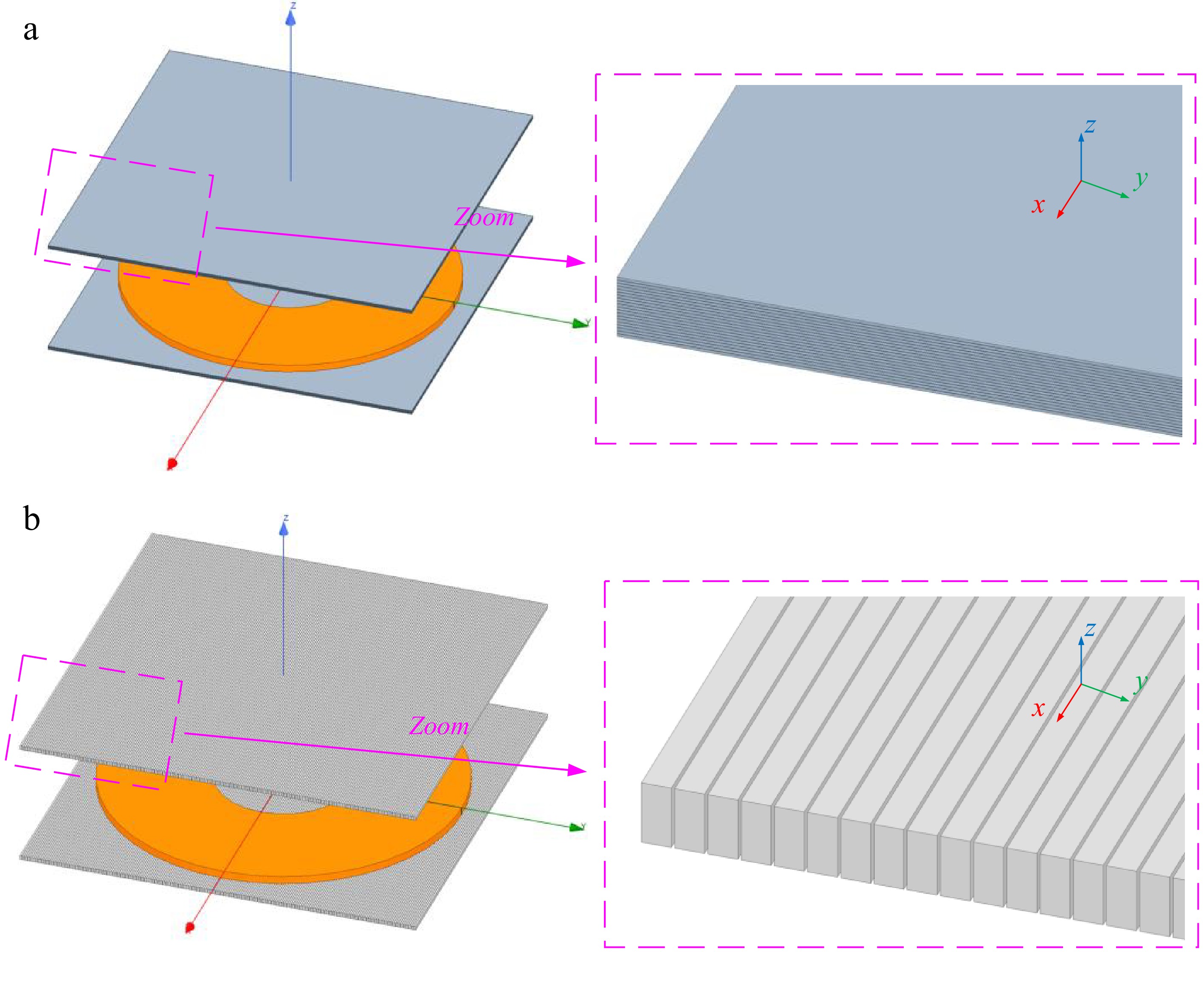
Figure 6.
Schematic diagram of laminated nanocrystalline ribbon core structure applications in unipolar coils. (a) Application of flat-laminated nanocrystalline. (b) Application of vertical-laminated nanocrystalline.
-
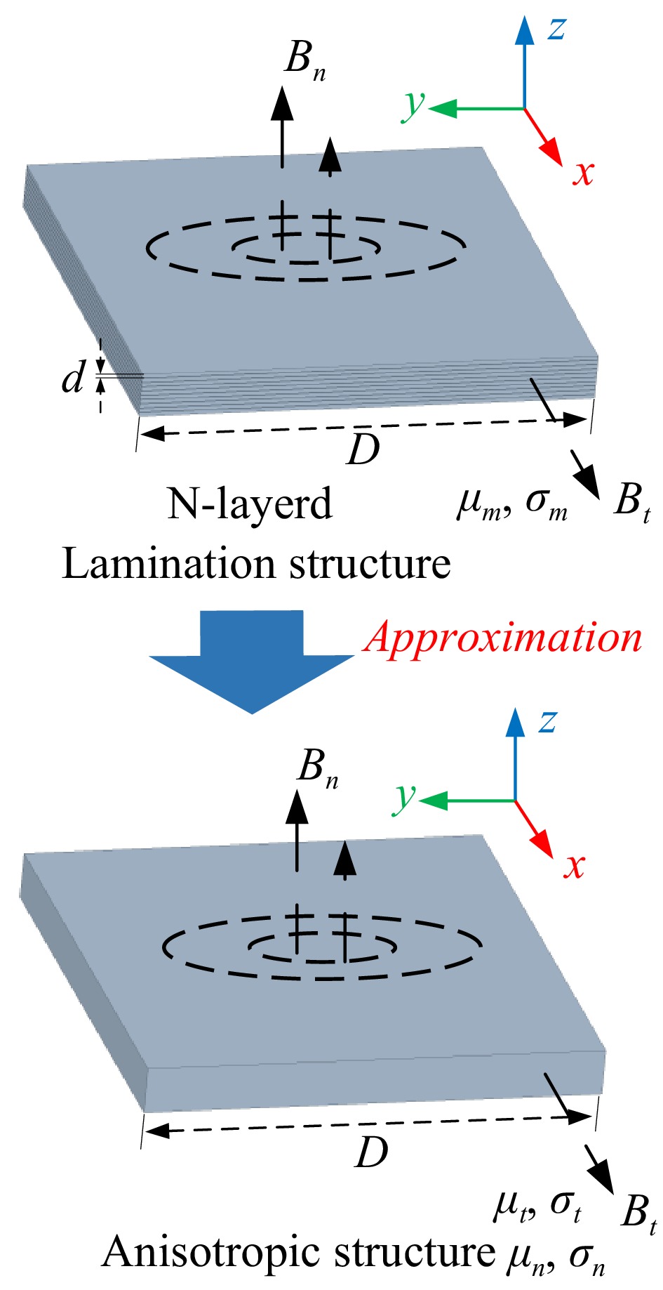
Figure 7.
Magnetic structure approximation by homogenization modeling method.
-
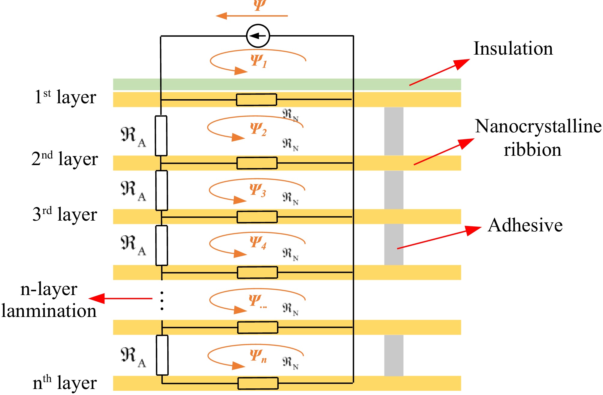
Figure 8.
The magnetic flux and magnetic reluctance distributions entering the n-layer laminated magnetic core structure.
-
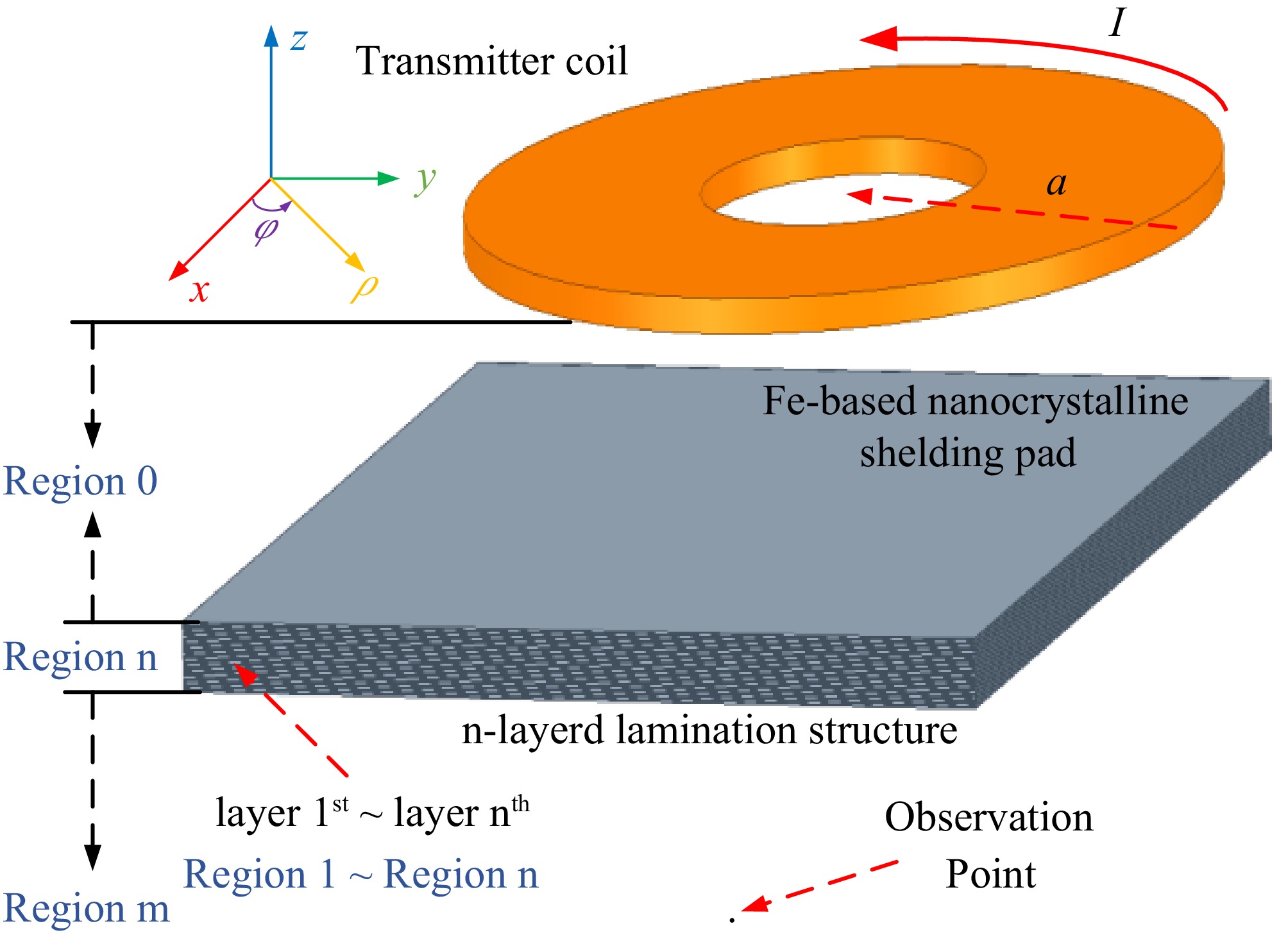
Figure 9.
Model establishment of the magnetic coupler with multi-layer laminated nanocrystalline ribbon core structure.
-
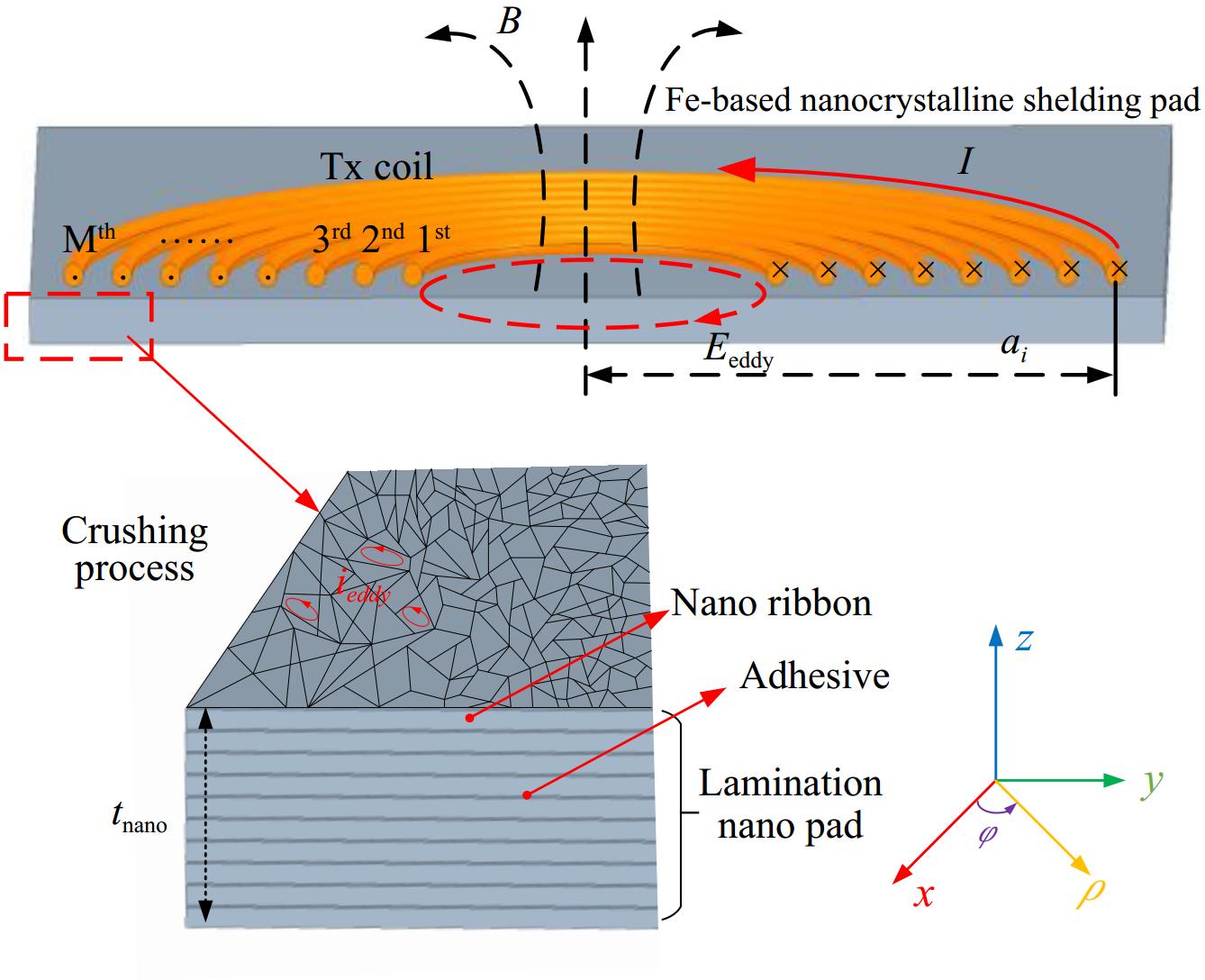
Figure 10.
Magnetic flux and electric field intensity analytical model.
-
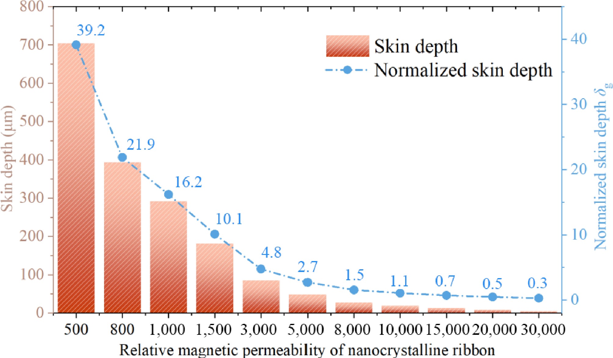
Figure 11.
The relationship between magnetic permeability and skin depth of nanocrystalline materials.
-
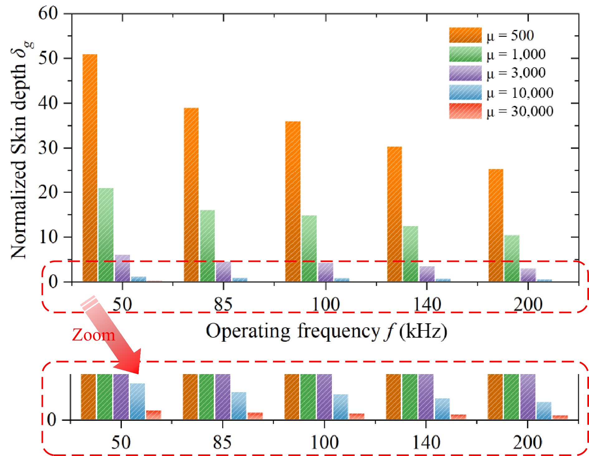
Figure 12.
The trend of normalized skin depth variation under different operating frequencies and relative magnetic permeability.
-
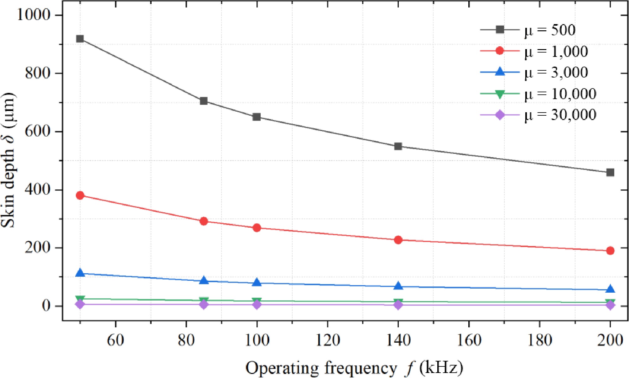
Figure 13.
The trend of skin depth variation under different operating frequencies and relative magnetic permeability.
-
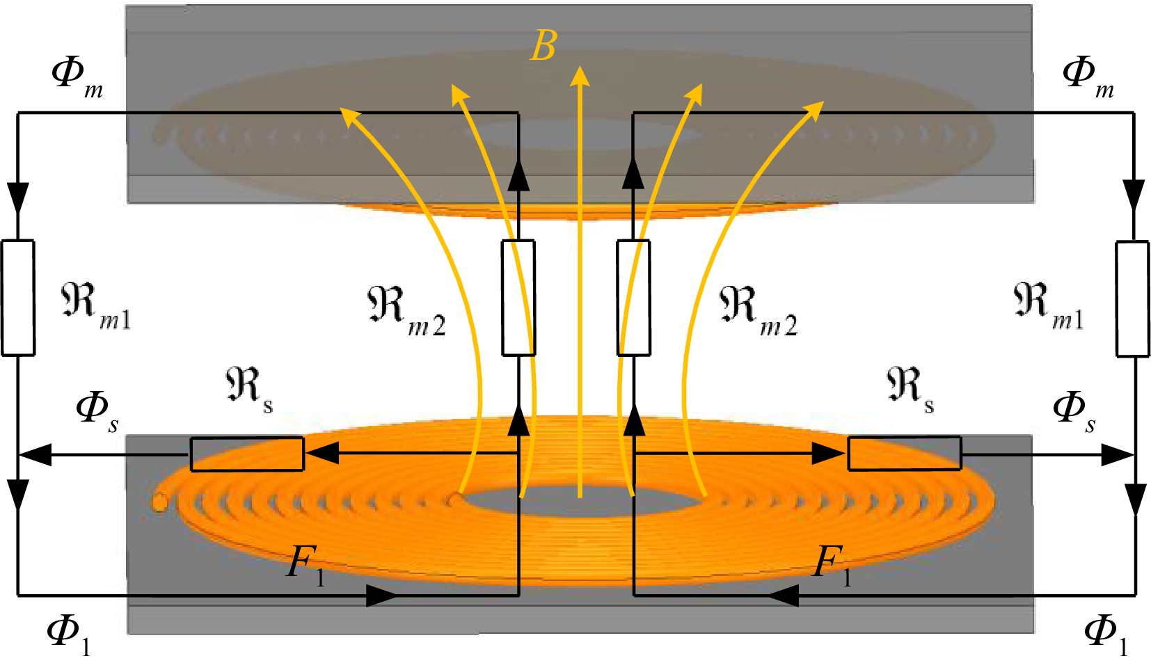
Figure 14.
Equivalent magnetic reluctance model of planar unipolar magnetic coupler.
-
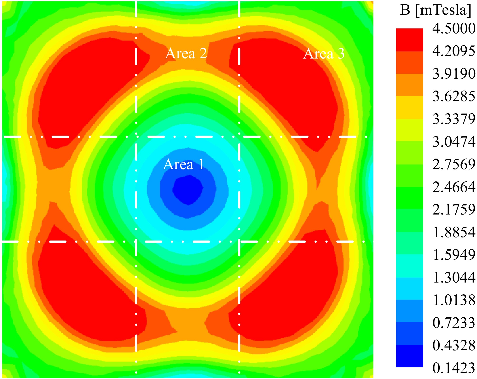
Figure 15.
Distribution of magnetic induction intensity in the magnetic core of a typical unipolar coil magnetic coupler.
-
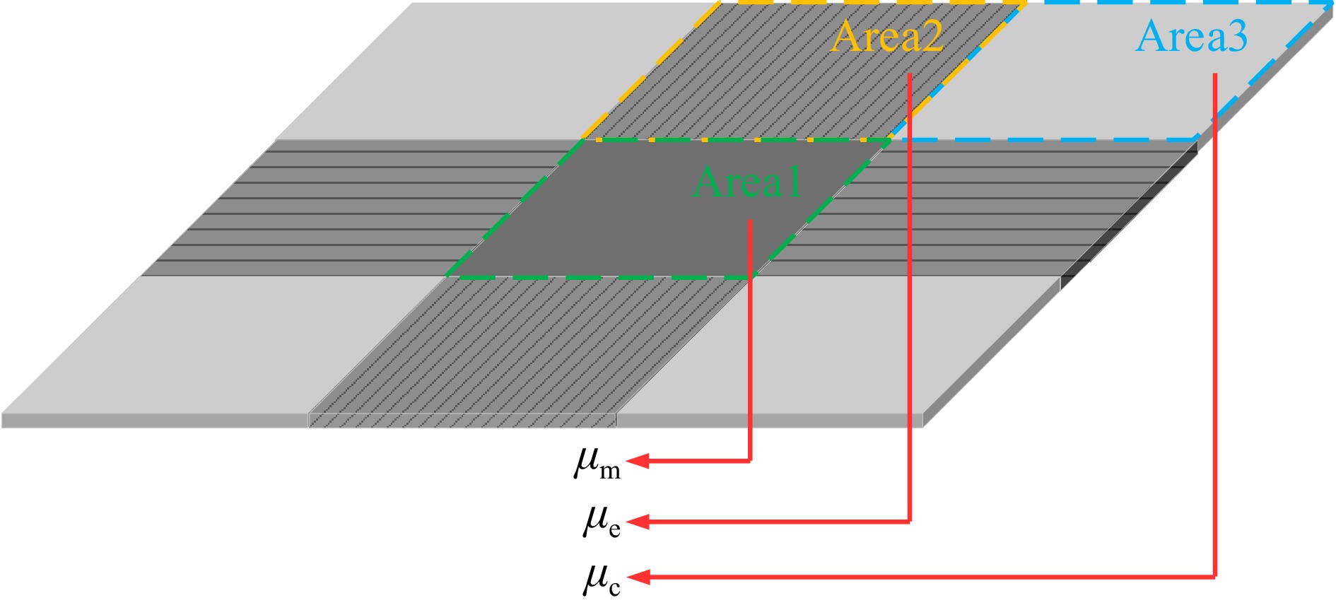
Figure 16.
Multi permeability hybrid nanocrystalline magnetic structure for unipolar coils.
-
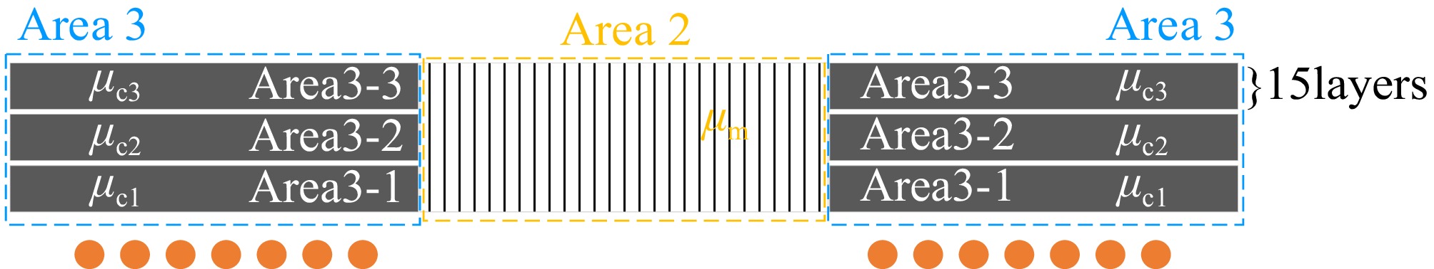
Figure 17.
Three-layer structure of the flat-laminated nanocrystalline in Area 3.
-
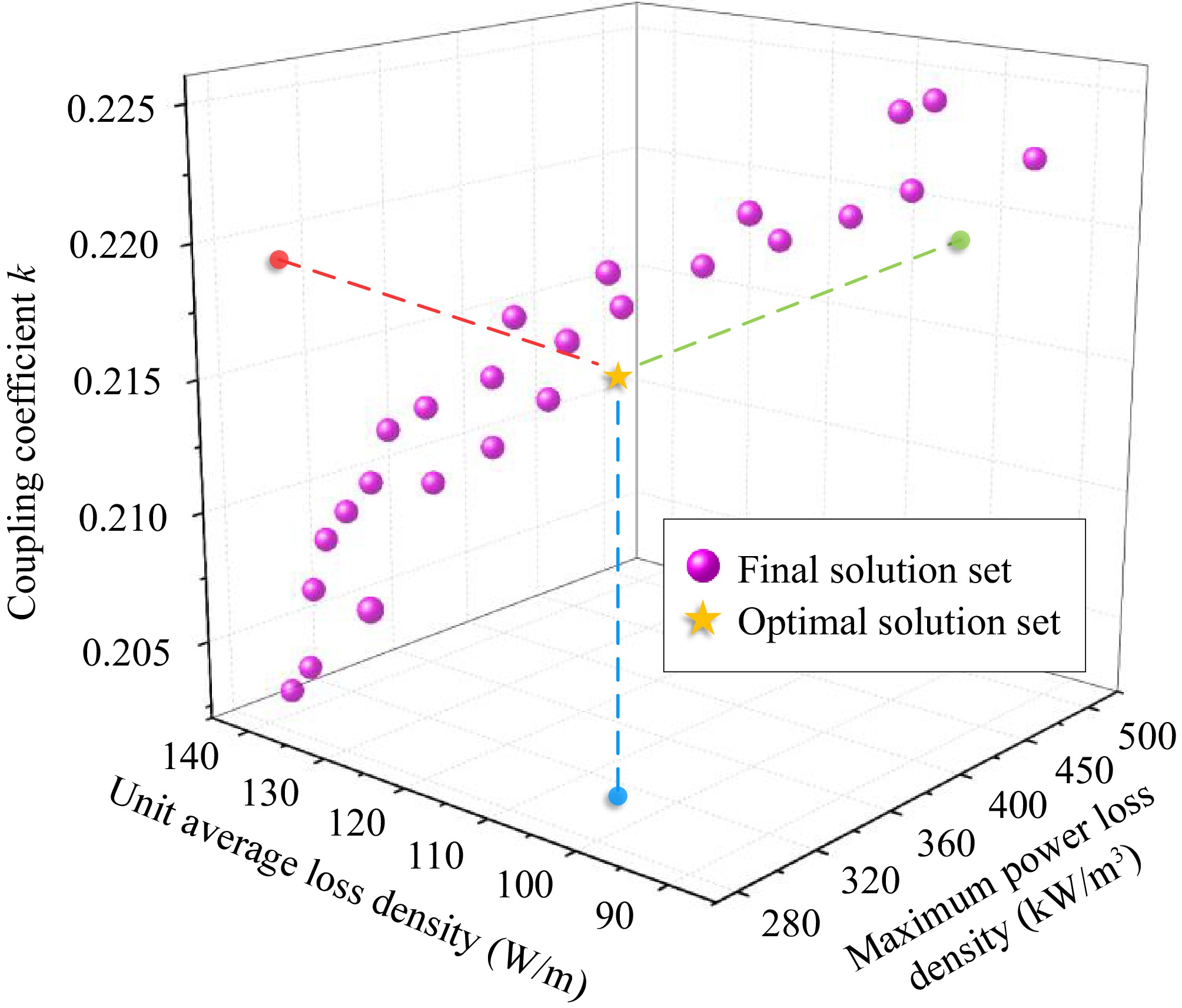
Figure 18.
Optimization design of magnetic permeability for multi permeability hybrid magnetic core structure.
-
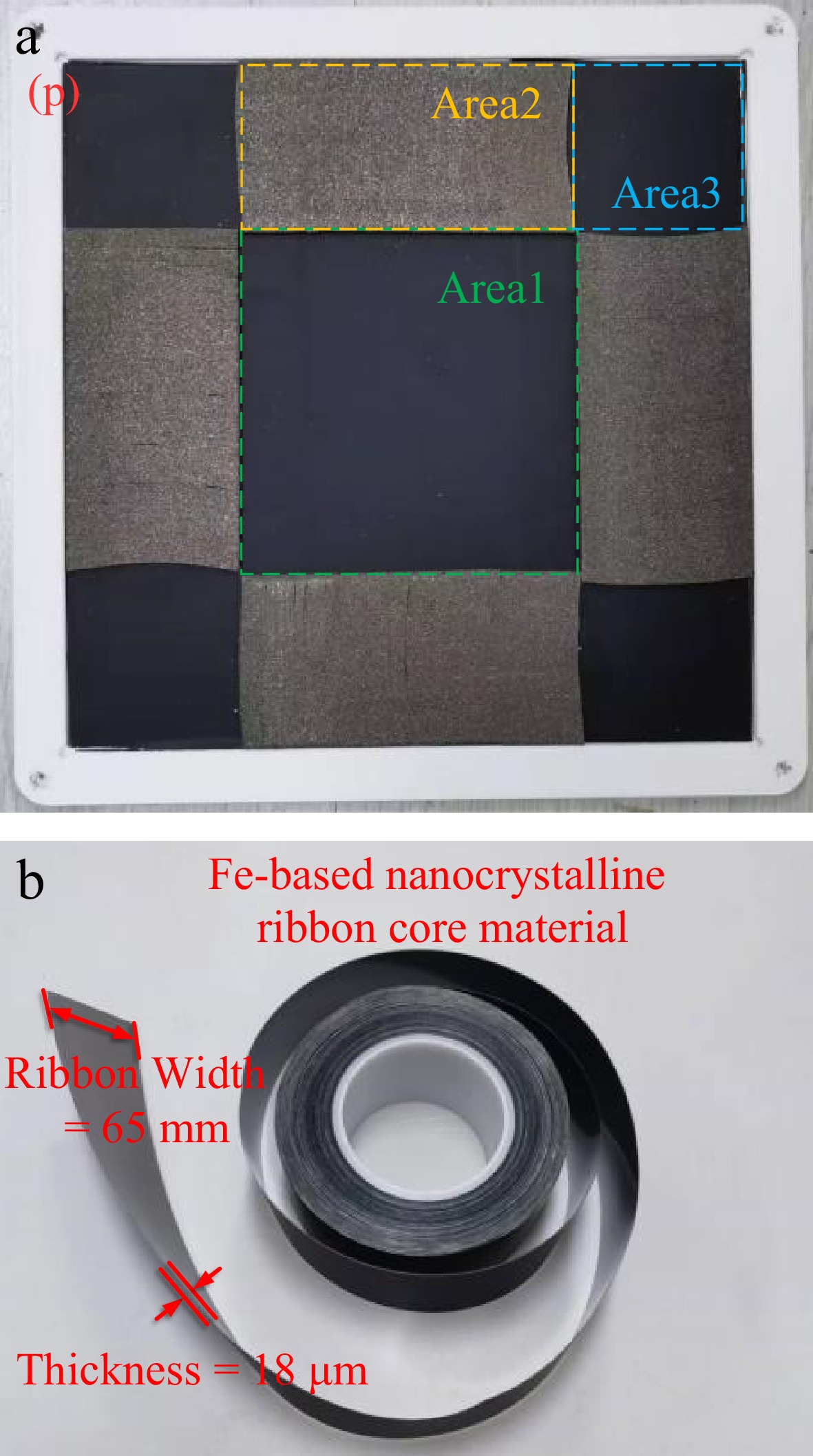
Figure 19.
Hybrid nanocrystalline magnetic core structure and its material units. (a) Proposed hybrid multi permeability nanocrystalline core structure. (b) Fe-based nanocrystalline ribbon core unit.
-
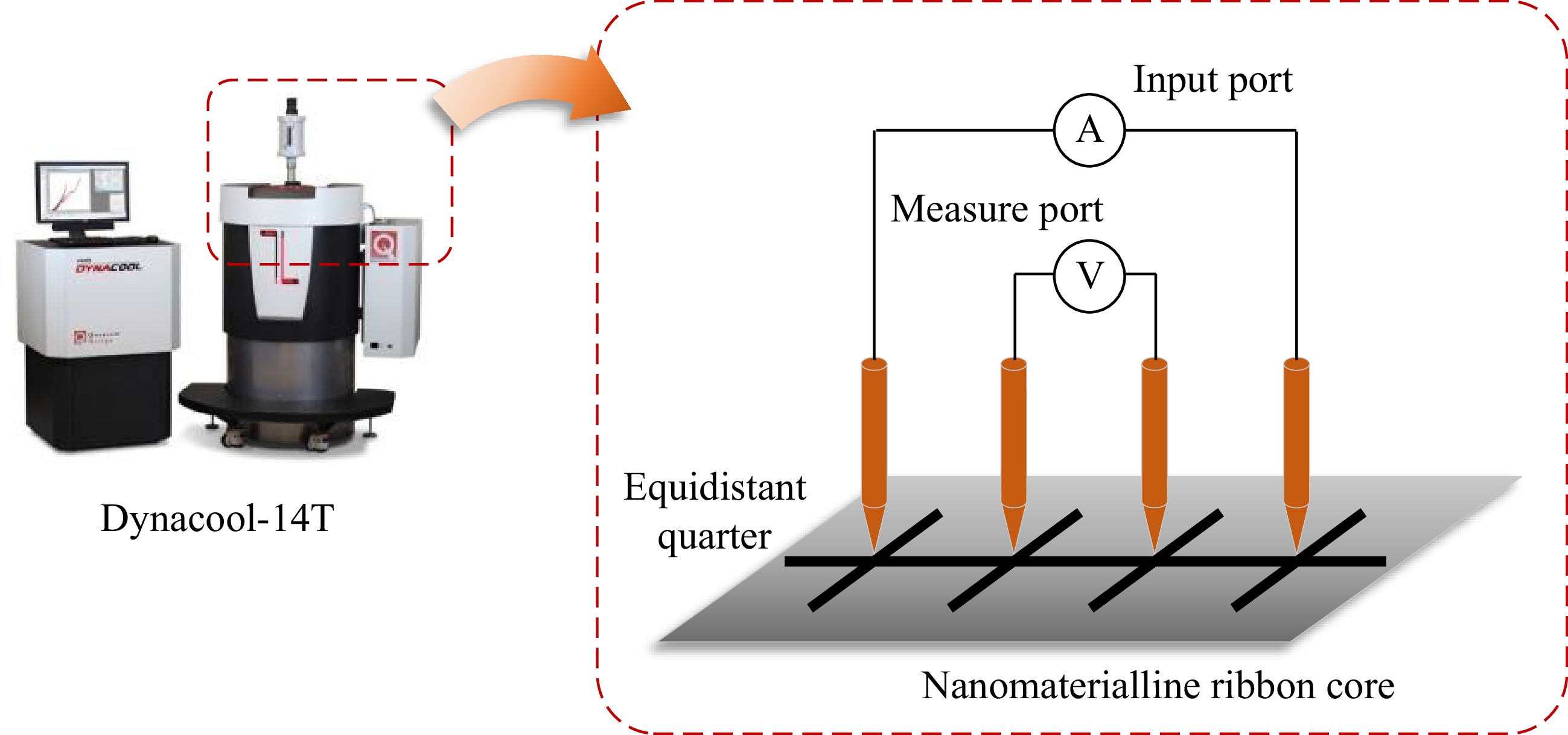
Figure 20.
The Dynacool-14T comprehensive physical property measurement system and four-probe method.
-
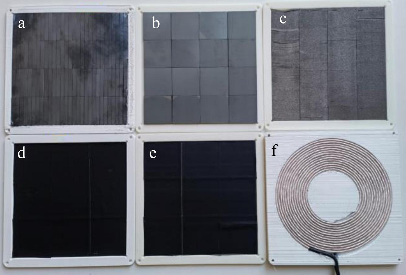
Figure 21.
Schematic of different magnetic cores and coupler.
-
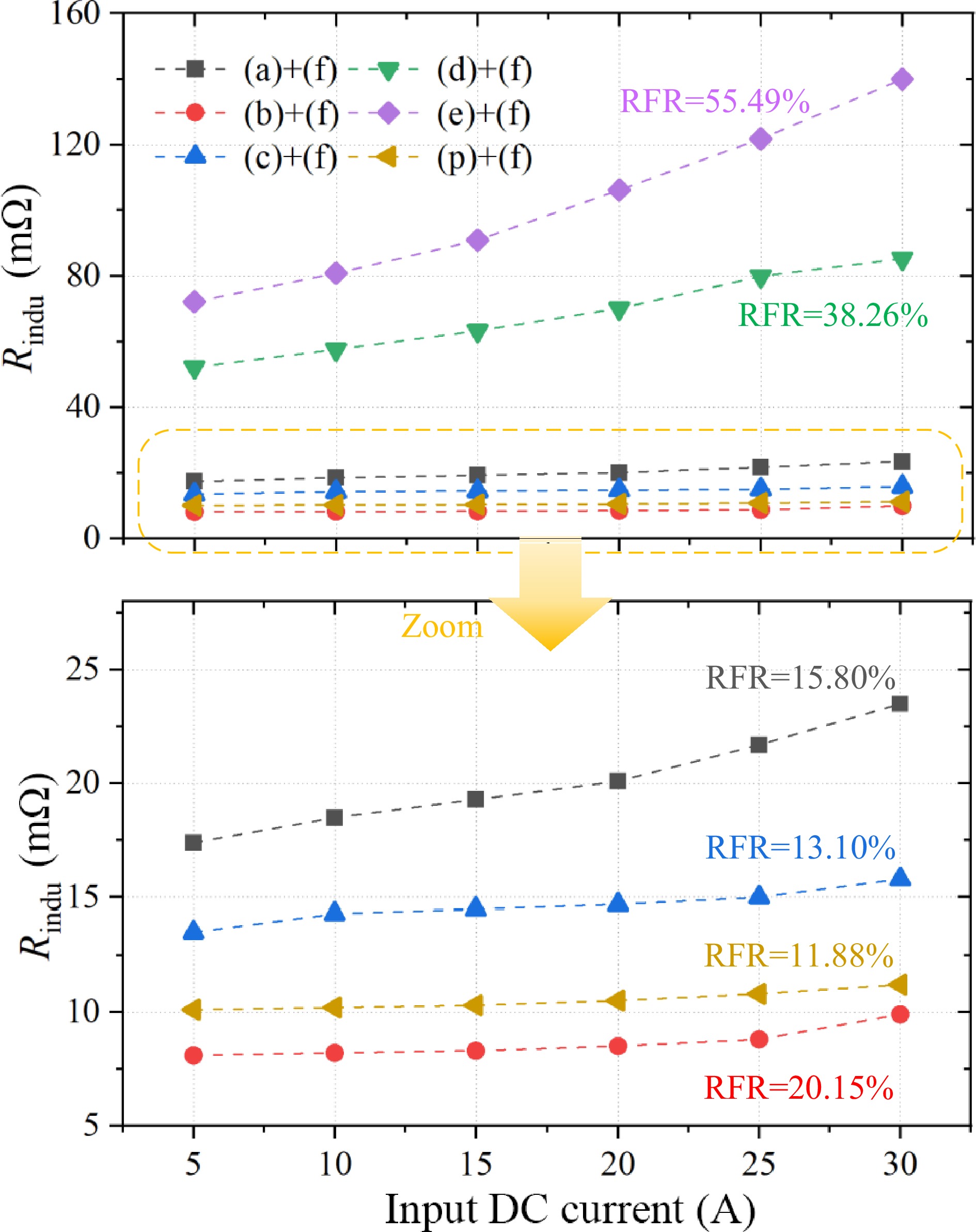
Figure 22.
The fluctuation of the AC resistance of the transmitter coil under different input DC current conditions.
-
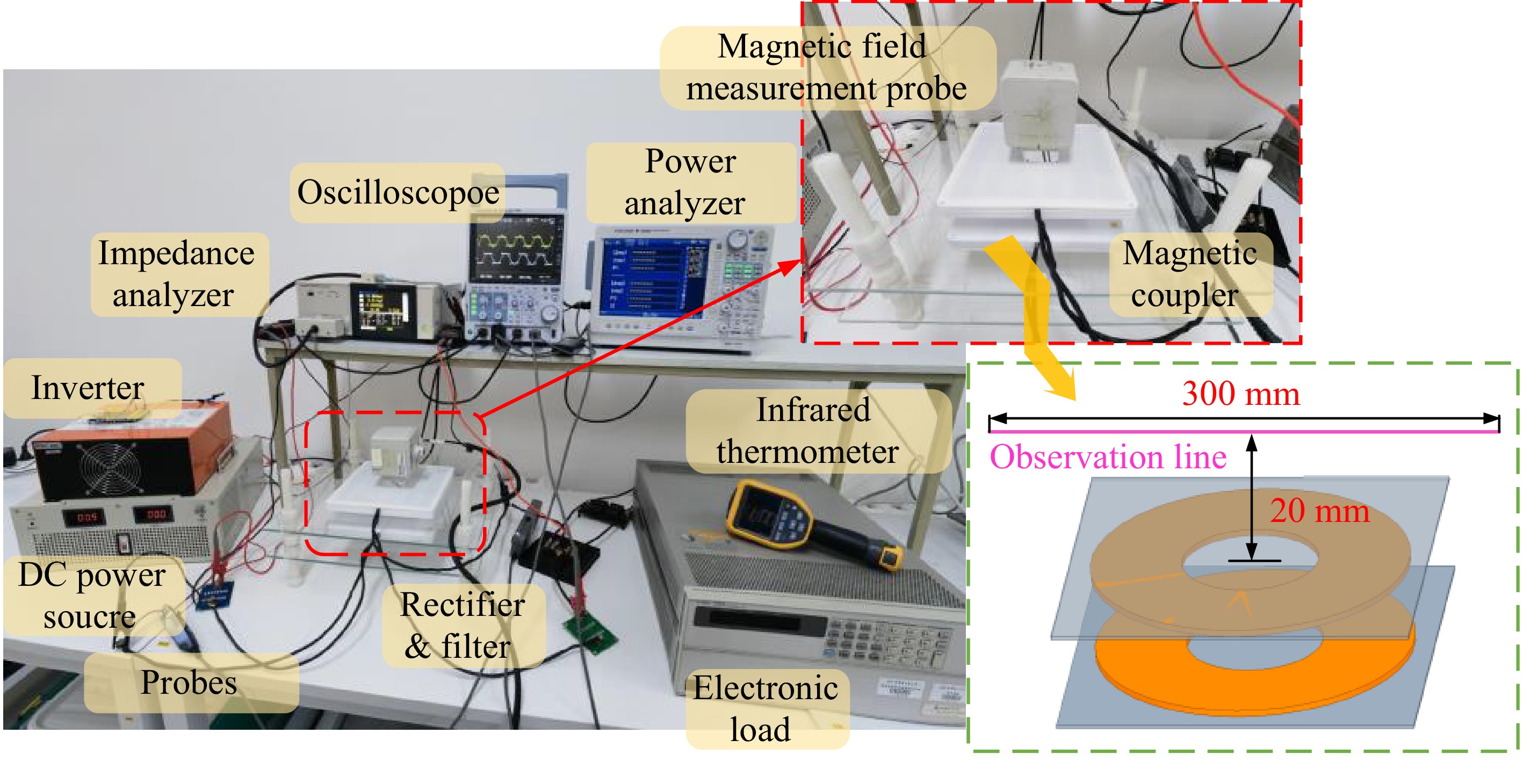
Figure 23.
The proposed 3 kW WPT system prototype and experimental platform with S-S topology.
-
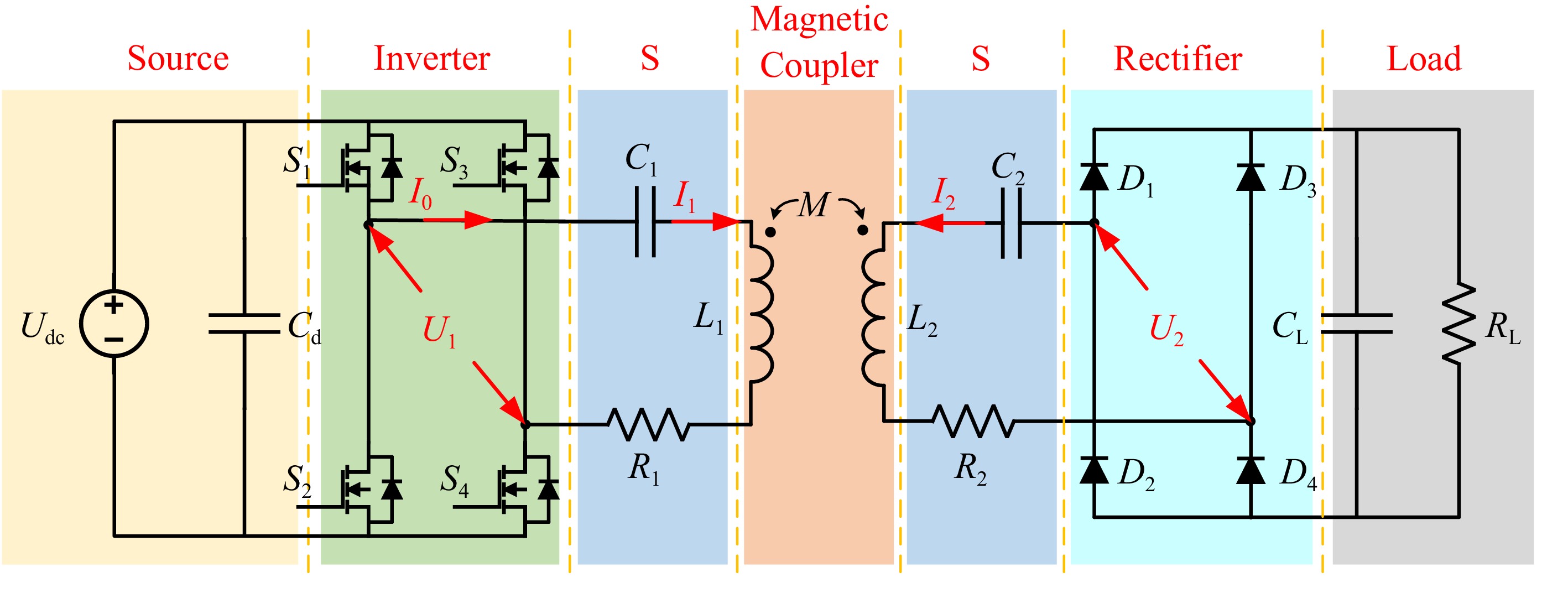
Figure 24.
Circuit schematic diagram of the experimental platform.
-
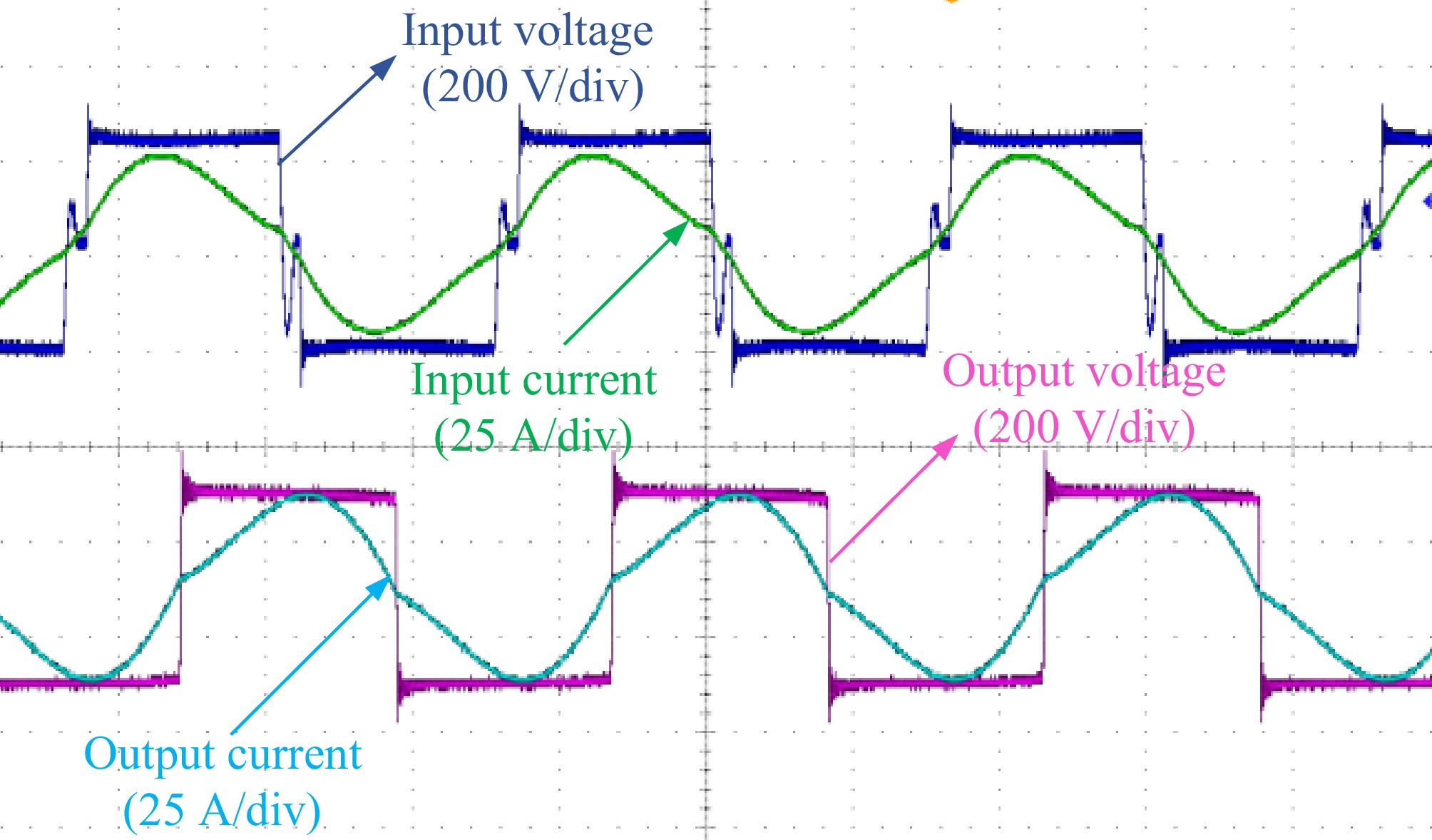
Figure 25.
Voltage and current waveform when transmitting 3 kW power.
-
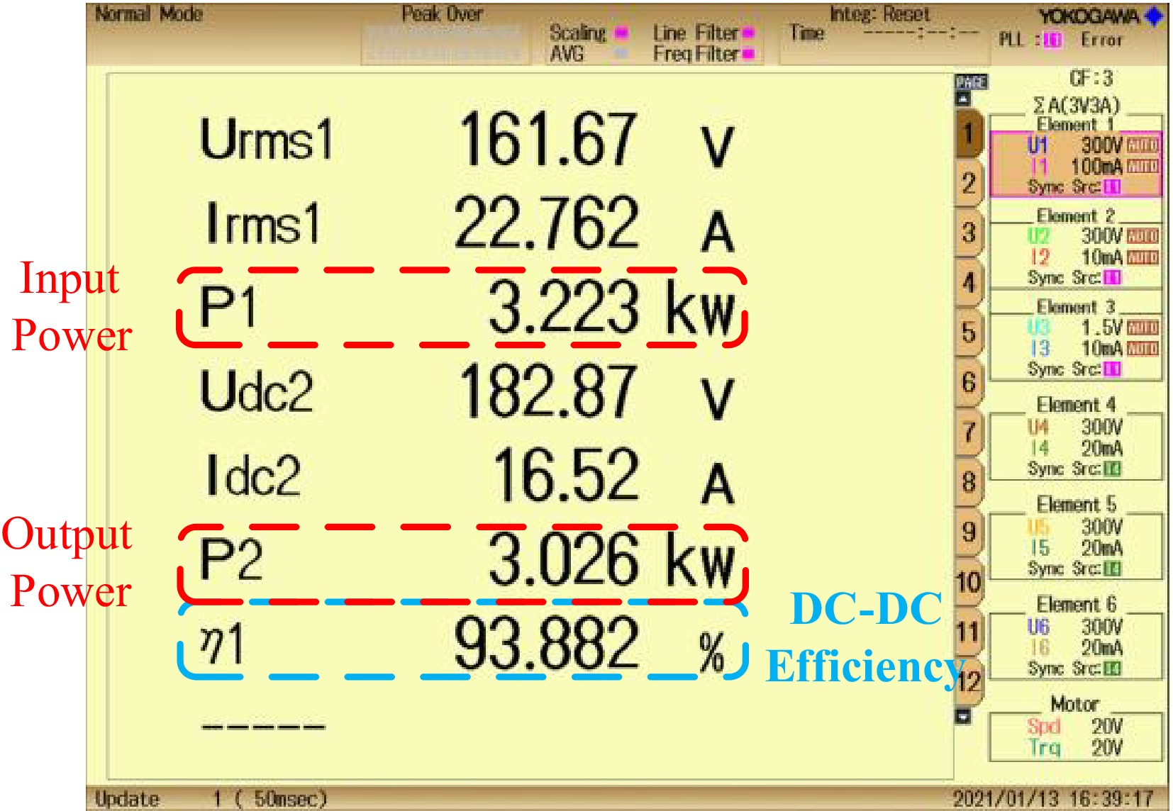
Figure 26.
System efficiency when transmitting 3 kW power at fully aligned state.
-
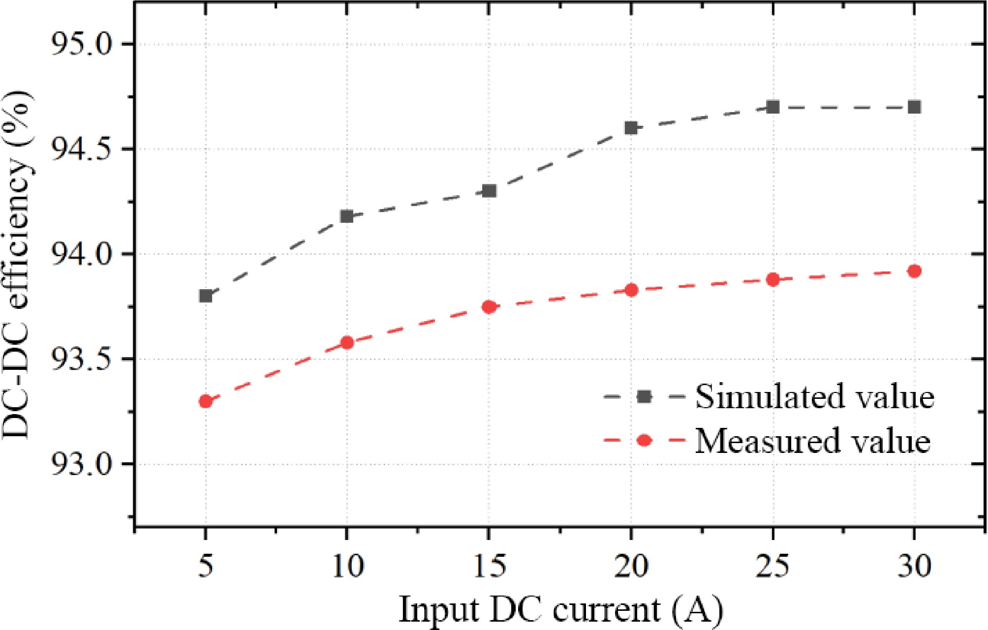
Figure 27.
System DC-DC efficiency under different input DC current conditions.
-
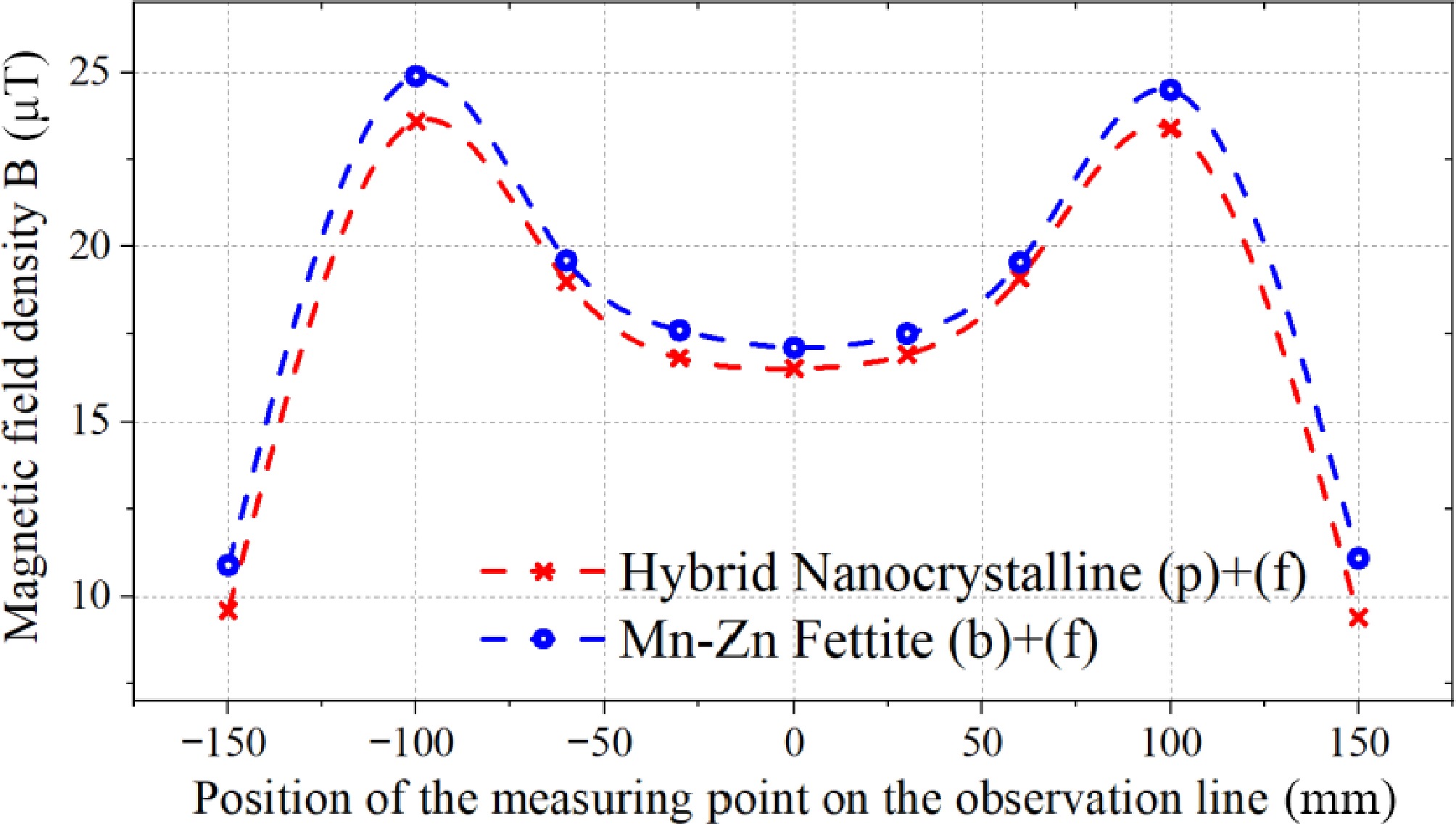
Figure 28.
Magnetic flux density curve measured along the observation line.
-
Symbol Parameter Fe-based Nanocrystalline @ YuNeng Tec u106 Mn-Zn Ferrite @ TDK PC95 Bs (T) @ 25 °C & H = 1,194 A/m Saturation magnetic induction 1.25 0.53 $\mu_0$ Initial permeability 100,000 3,300 $\mu_{\max} $ Maximum magnetic permeability 1,000,000 6,000 Hc (A/m) @ 25 °C&H = 1,194 A/m Coercivity 1.60 9.5 Tc (°C) Curie temperature 570 215 ρD (kg/m3) Bulk density 7,200 4,900 PLoss (kW/m3) @ 100 kHz & 25 °C & 0.2 T Core loss 250 350 PLoss (kW/m3) @ 100 kHz & 100 °C & 0.2 T Core loss 180 290 ρR (Ω·m) Volume resistivity 1.1 × 10⁻⁶ 6 Table 1.
Comparison of basic parameters between typical Fe-based nanocrystalline and Mn-Zn ferrite materials.
-
Label Material Single size Parameters (a) Vertical cutting nanocrystalline 50 mm width, multiple layers sheets, 2 mm thickness µ = 1,000 (b) PC95 ferrite 50 mm * 50 mm * 5 mm µ = 3,300 (c) Diagonal cutting nanocrystalline 50 mm width, multiple layers sheets, 2 mm thickness µ = 1,000 (d) Flat laminated nanocrystalline 50 mm width, multiple layers, 2 mm thickness µ = 1,000 (e) Flat laminated nanocrystalline 50 mm width, multiple layers,
0.5 mm thicknessµ = 1,000 (p) Hybrid multi permeability nanocrystalline 200 mm * 200 mm * 2 mm µ = 700 µ = 1,400 µ = 3,000 (f) Copper coil with resin shell 0.05 mm * 2,500 strands, spiral tight winding N = 14 Table 2.
Parameters of the core and coil in the experiment.
-
Magnetic coupler L1 Simulated value (μH) L1 Measured value (μH) R1 Simulated value (mΩ) R1 Measured value (mΩ) M Simulated value (μH) M Measured value (μH) Only (f) 31.8 33.6 22.5 25.8 9.2 9.6 (a) + (f) 49.8 47.4 47.1 43 21.5 21.9 (b) + (f) 58.4 54.3 33.1 33.9 26.1 26.7 (c) + (f) 51.9 50.5 42.8 39.4 23.8 24.4 (d) + (f) 44.5 51.9 87.5 77.8 21.7 20.1 (e) + (f) 41.4 47.1 102.7 97.9 19.1 18.6 (p) + (f) 53.3 51.7 40.1 38.8 24.0 24.9 Table 3.
Impedance analyzer measurement and finite element simulation results of multiple sets of magnetic core pads,.
-
Parameters Description Value Udc Input DC voltage 160 V f Operating frequency 85 kHz L1 Primary self-inductance 53.3 μH C1 Primary compensation capacitance 65.1 nF L2 Secondary self-inductance 53.7 μH C2 Secondary compensation capacitance 65.2 nF RL Load resistance 11 Ω Table 4.
Electrical parameter values of the experimental platform.
Figures
(28)
Tables
(4)