-
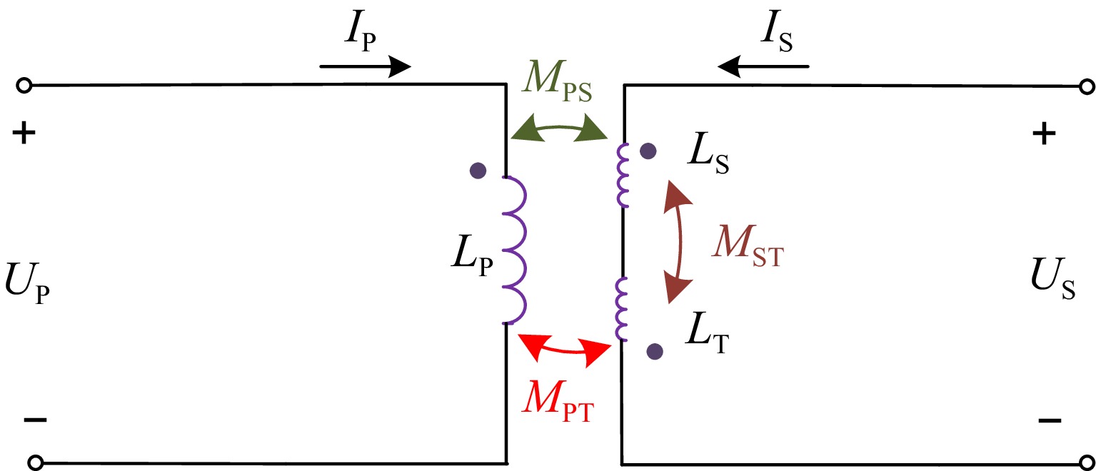
Figure 1.
Equivalent circuit of the proposed coil.
-
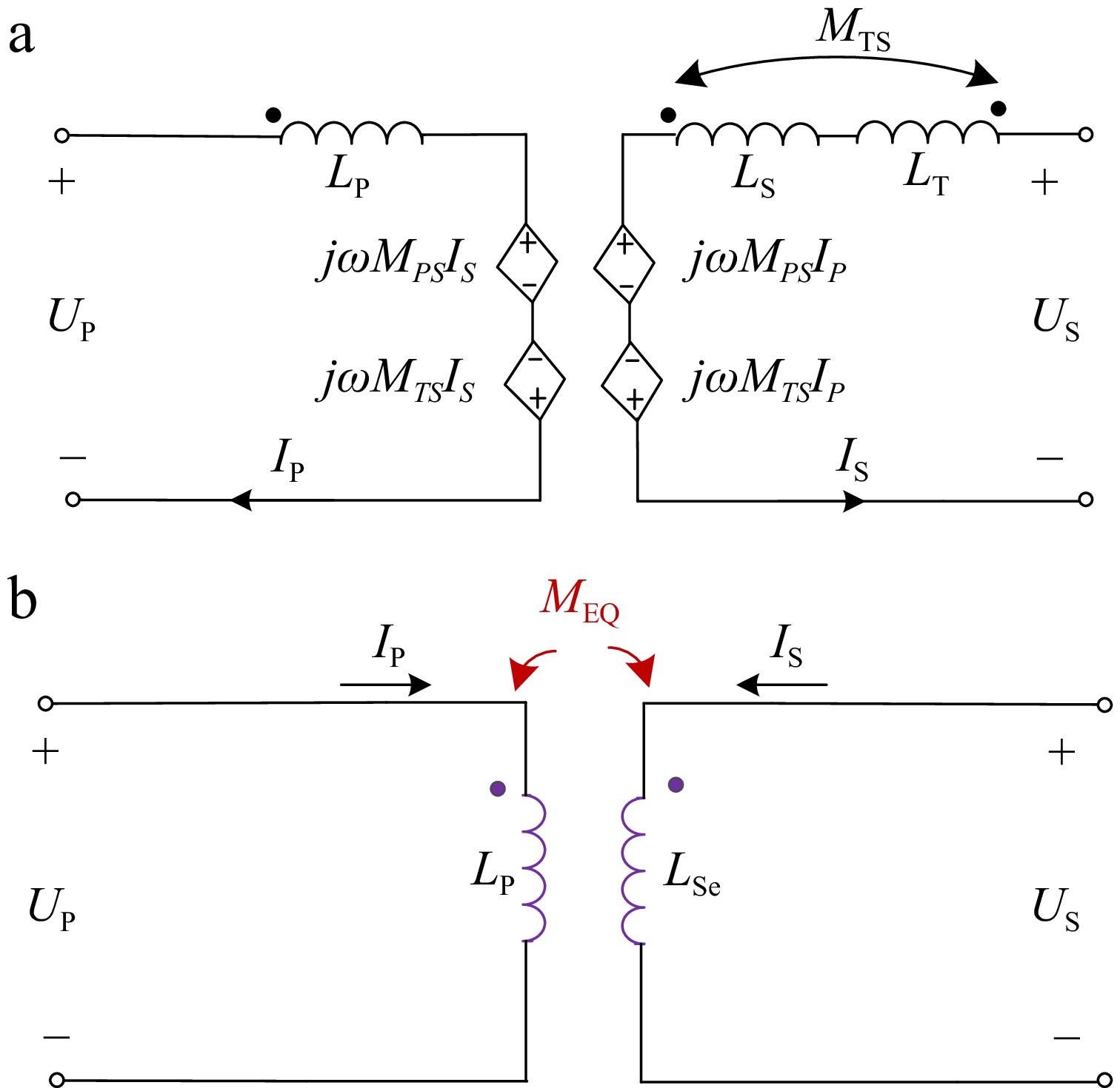
Figure 2.
M model and equivalent model of the proposed coil. (a) M model. (b) Equivalent model.
-
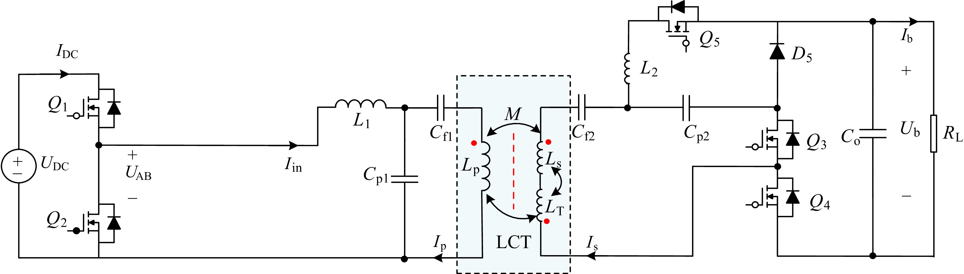
Figure 3.
Circuit diagram of the proposed system.
-
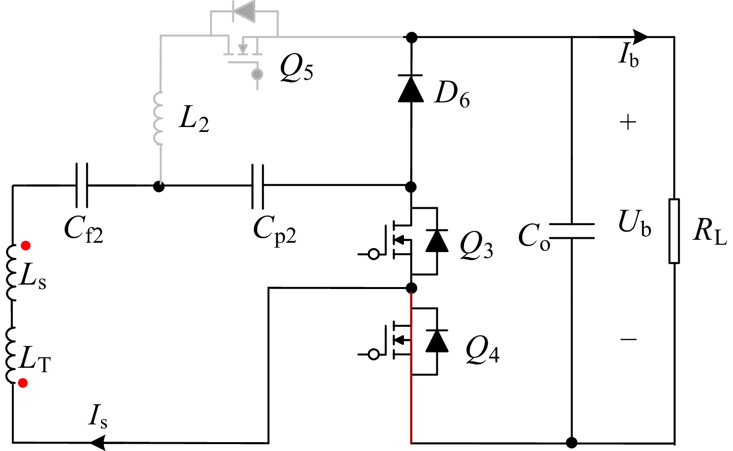
Figure 4.
Equivalent circuit in CV mode.
-
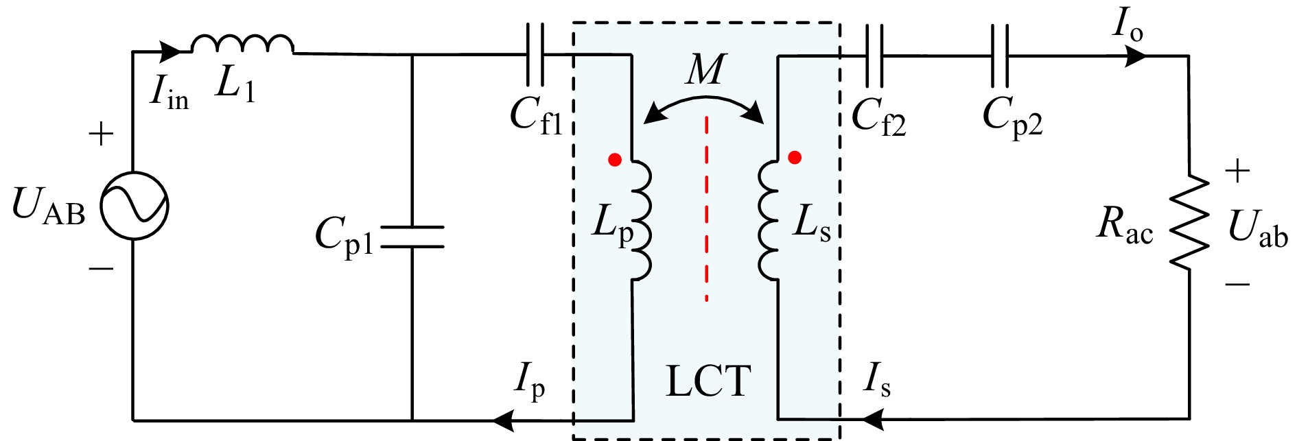
Figure 5.
Equivalent resonant network in CV mode.
-
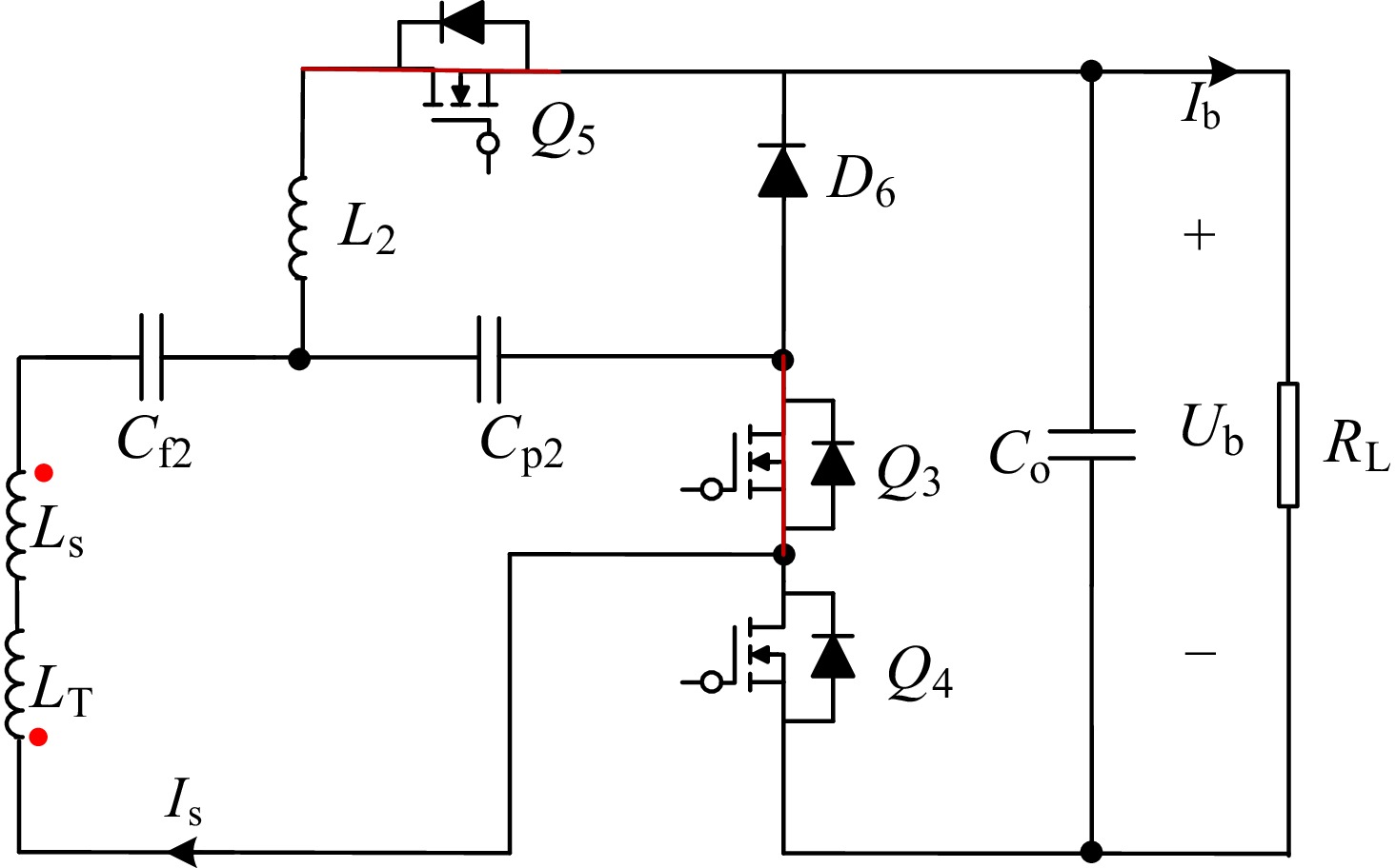
Figure 6.
Equivalent circuit in CC mode.
-
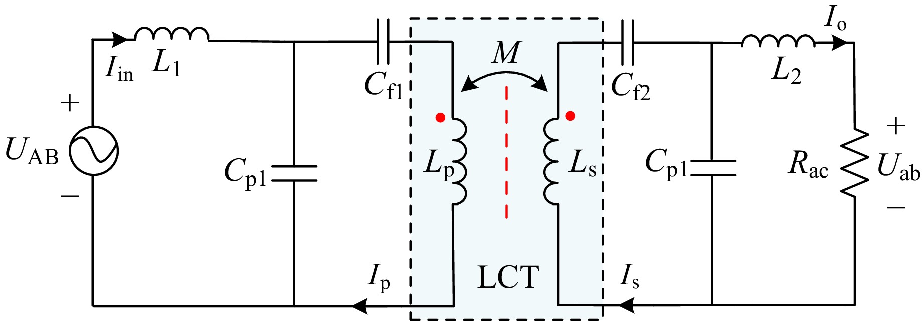
Figure 7.
Equivalent circuit of the proposed IPT system in CC mode.
-
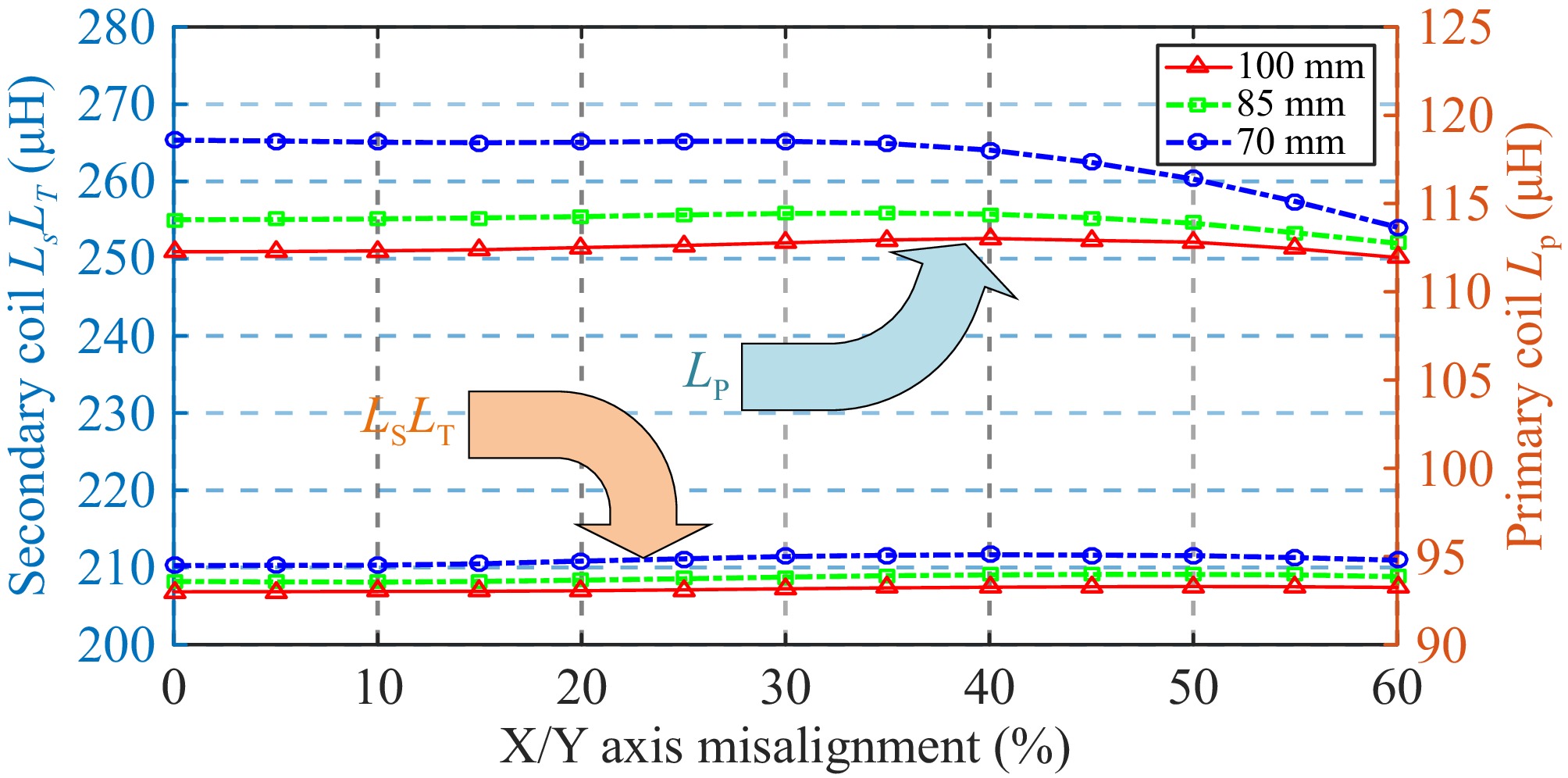
Figure 8.
Self-inductance change of the proposed three-coil structure.
-
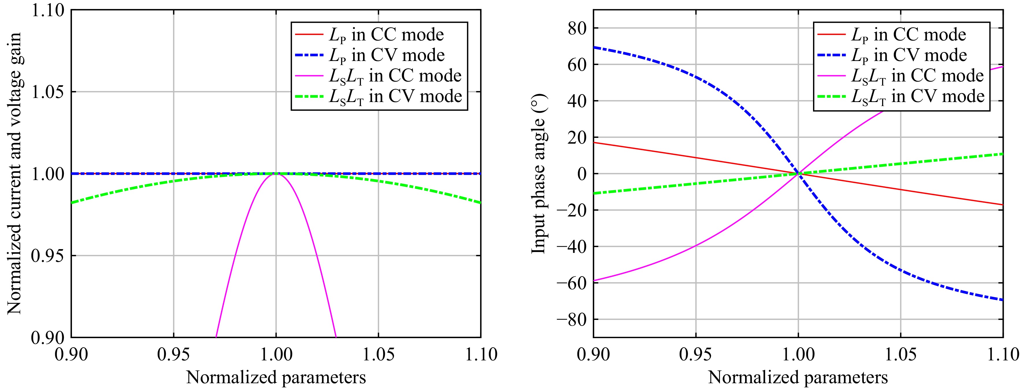
Figure 9.
Relationship curves between the normalized current/voltage gain and input phase angle with the normalized self-inductance value in CC mode and CV mode.
-
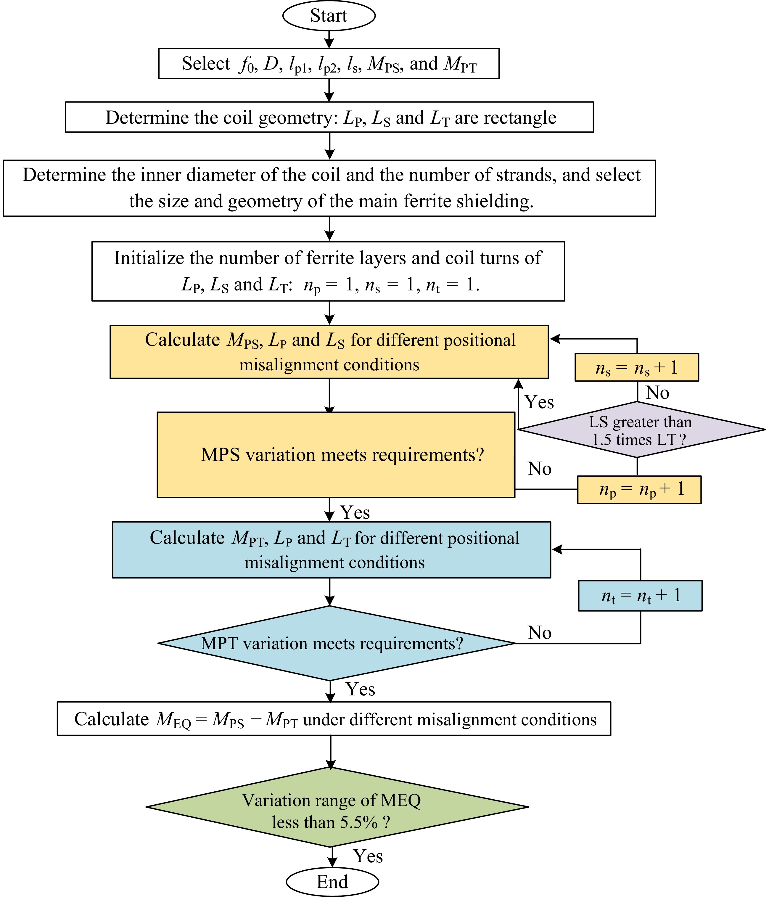
Figure 10.
Flow chart of the proposed coupler.
-
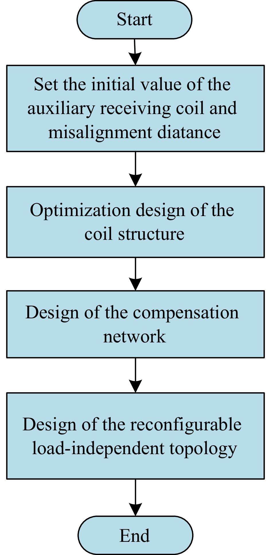
Figure 11.
Flow chart of the proposed IPT system.
-
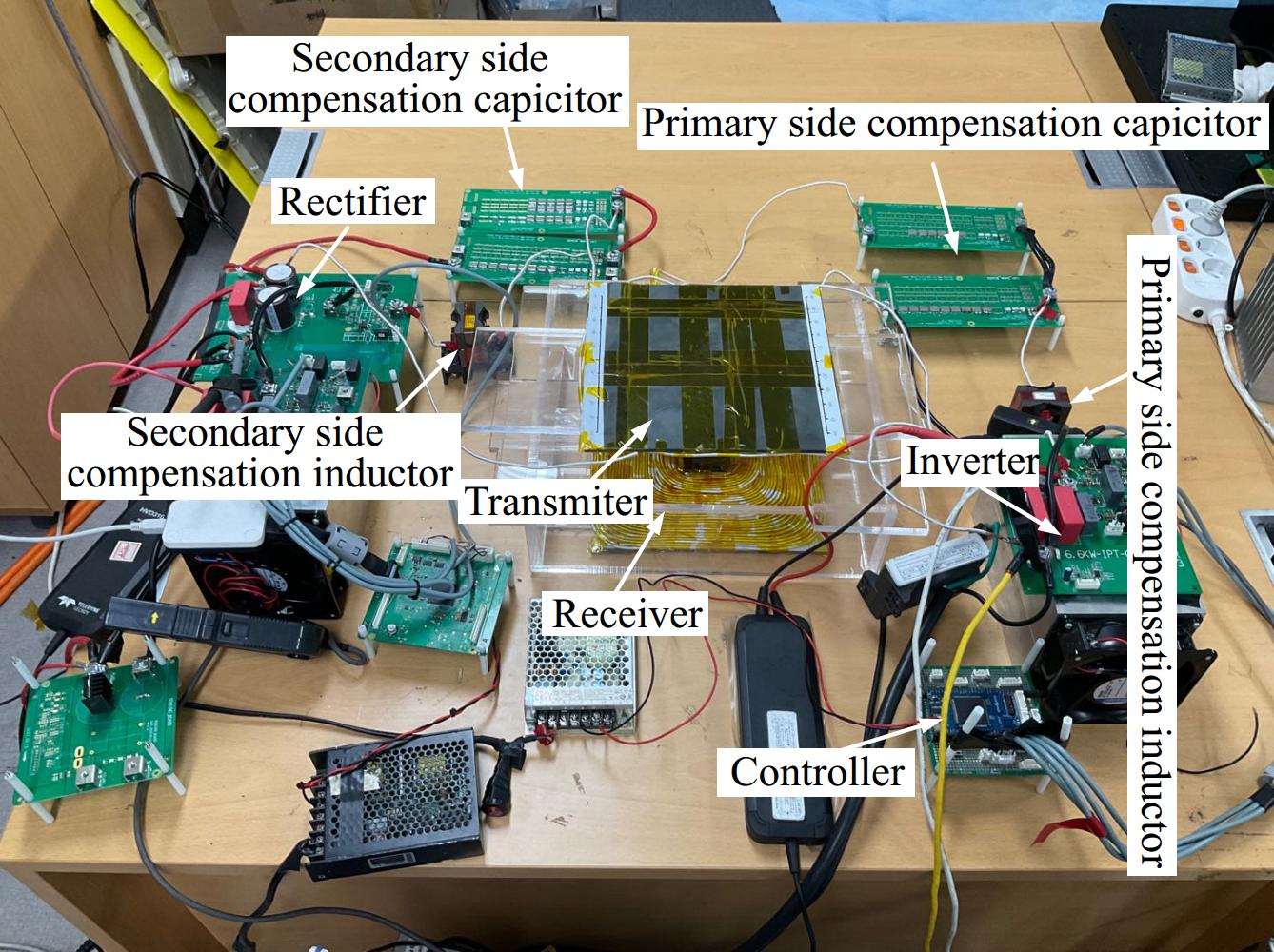
Figure 12.
Experiment setup.
-
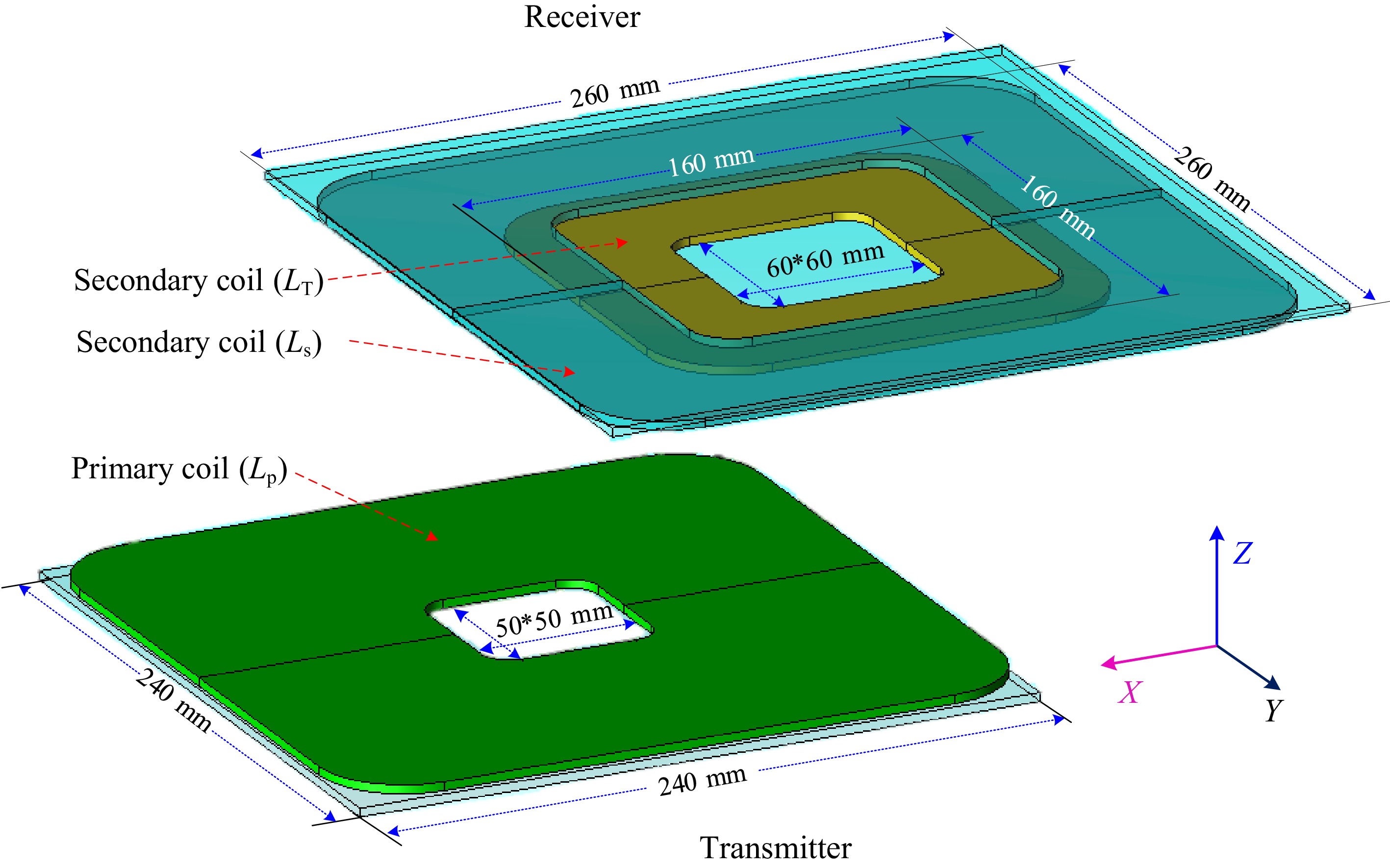
Figure 13.
JMAG simulation model.
-
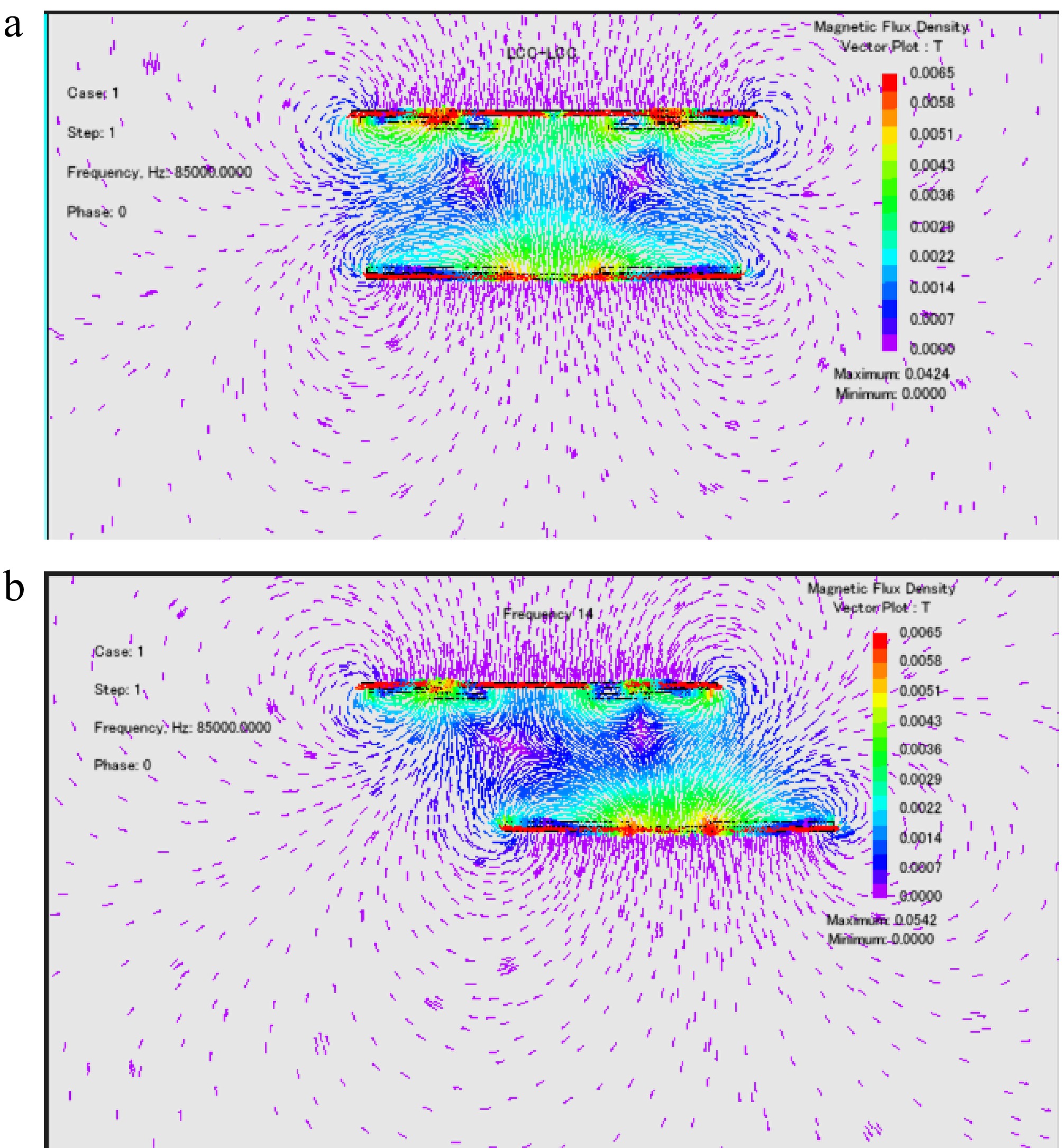
Figure 14.
Simulated magnetic flux density under (a) alignment. (b) X- or Y-axis misalignment with 42% deviation.
-
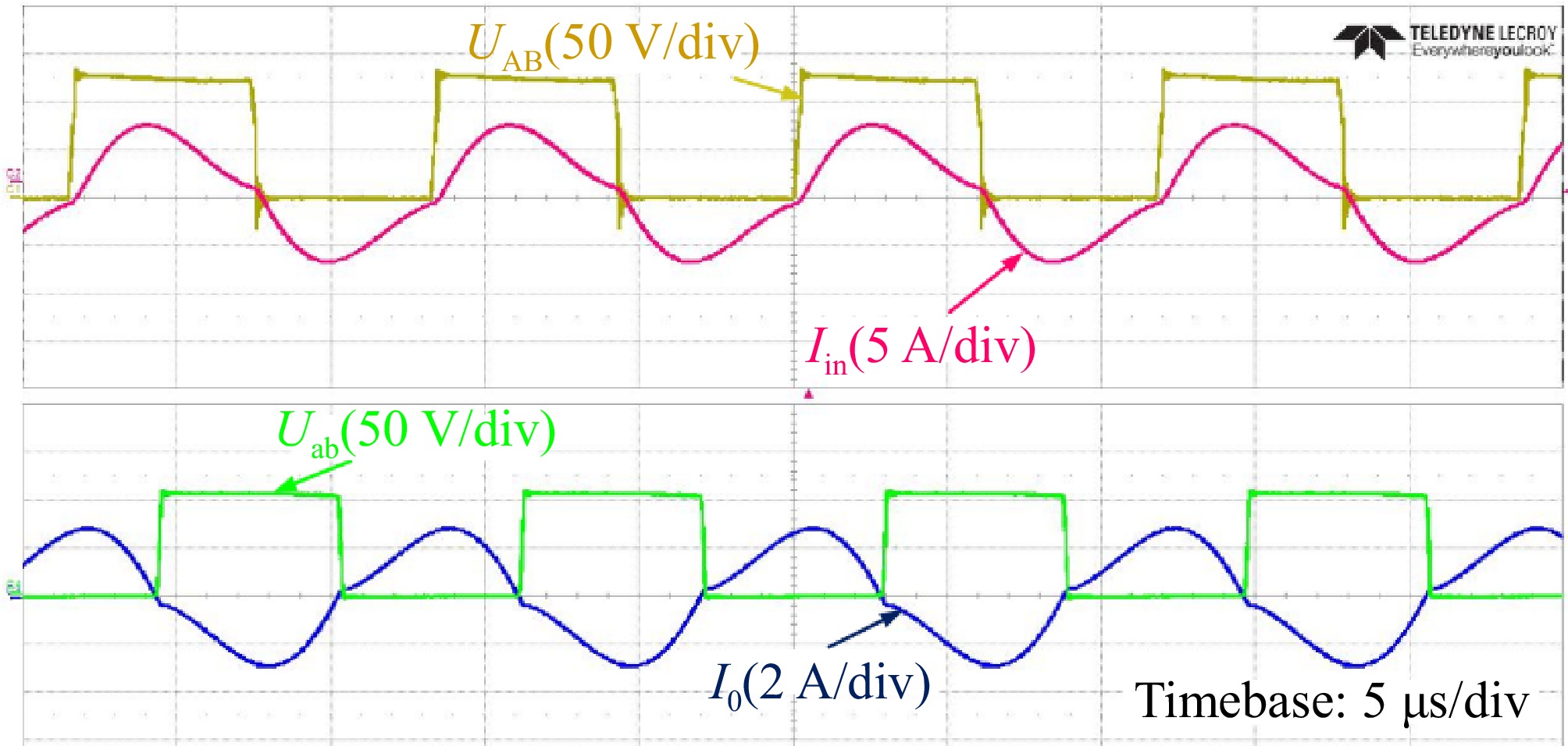
Figure 15.
Experimental waveforms of UAB, Uab, Iin, and Io in the CC mode.
-
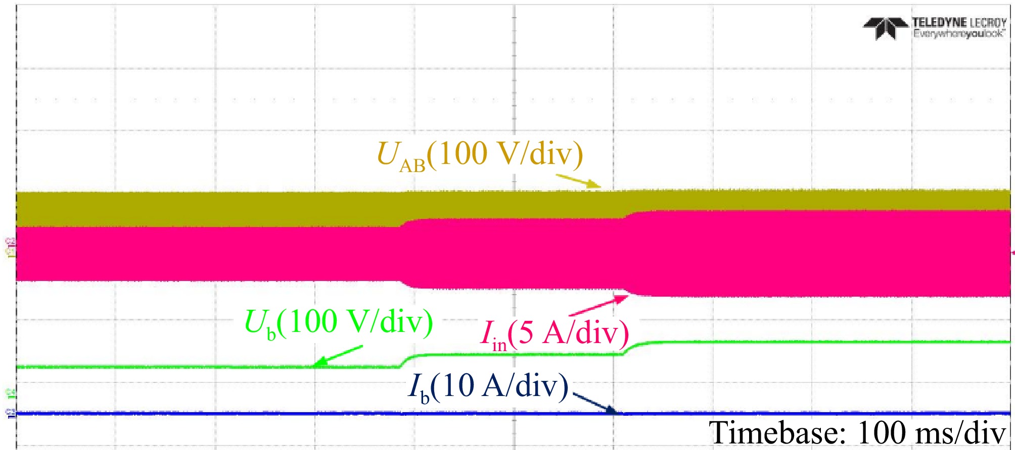
Figure 16.
Experimental waveforms of Ub and Ib in the CC mode with RL varying from 24 to 32 Ω.
-
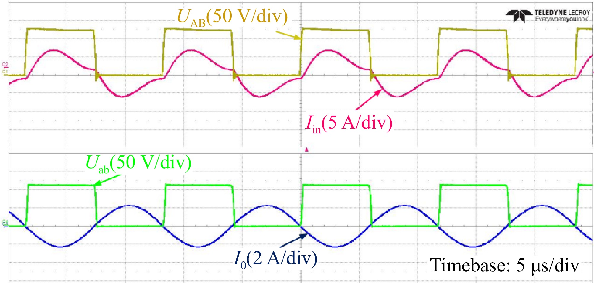
Figure 17.
Experimental waveforms of UAB, Uab, Iin, and Io in the CV mode.
-
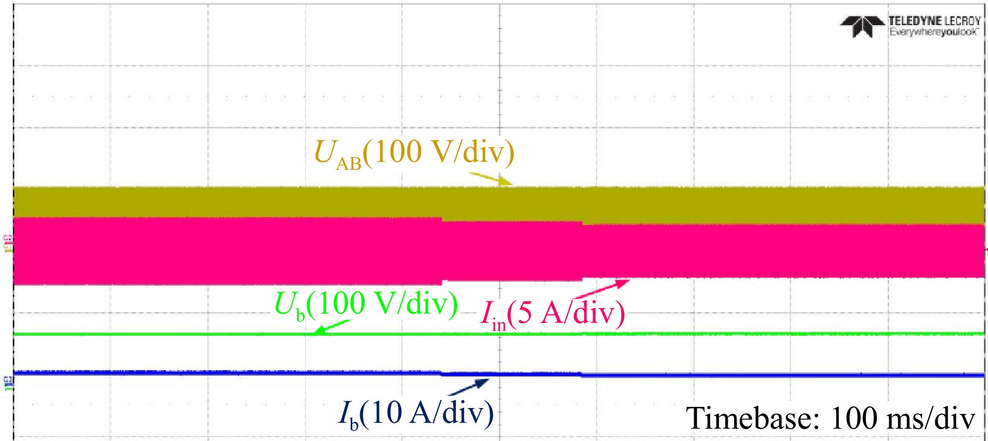
Figure 18.
Experimental waveforms of Ub and Ib in the CV mode with RL varying from 36 to 50 Ω.
-
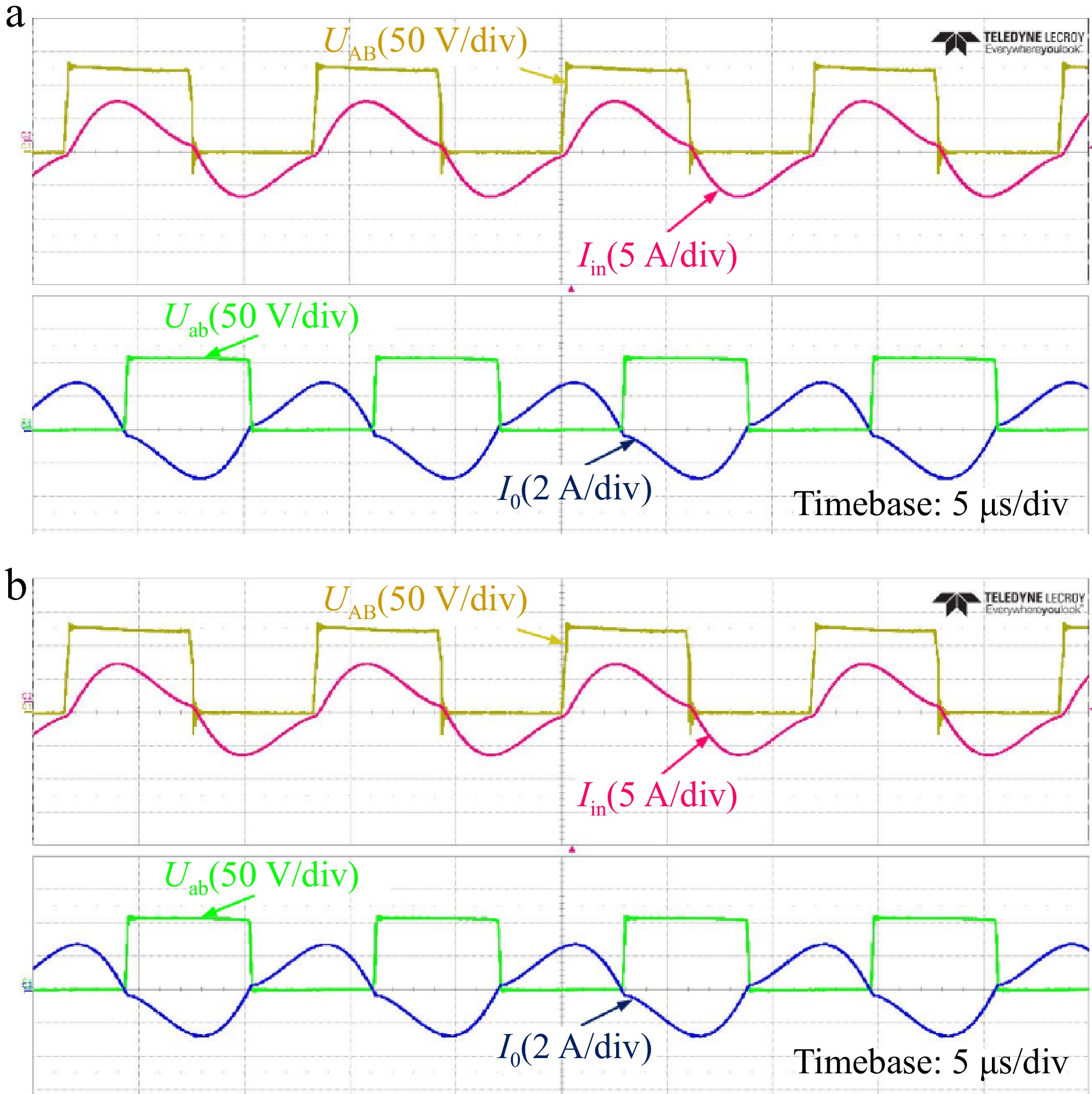
Figure 19.
Experimental waveforms of alignment and misalignment condition in CC mode. (a) Alignment condition. (b) Misalignment condition.
-
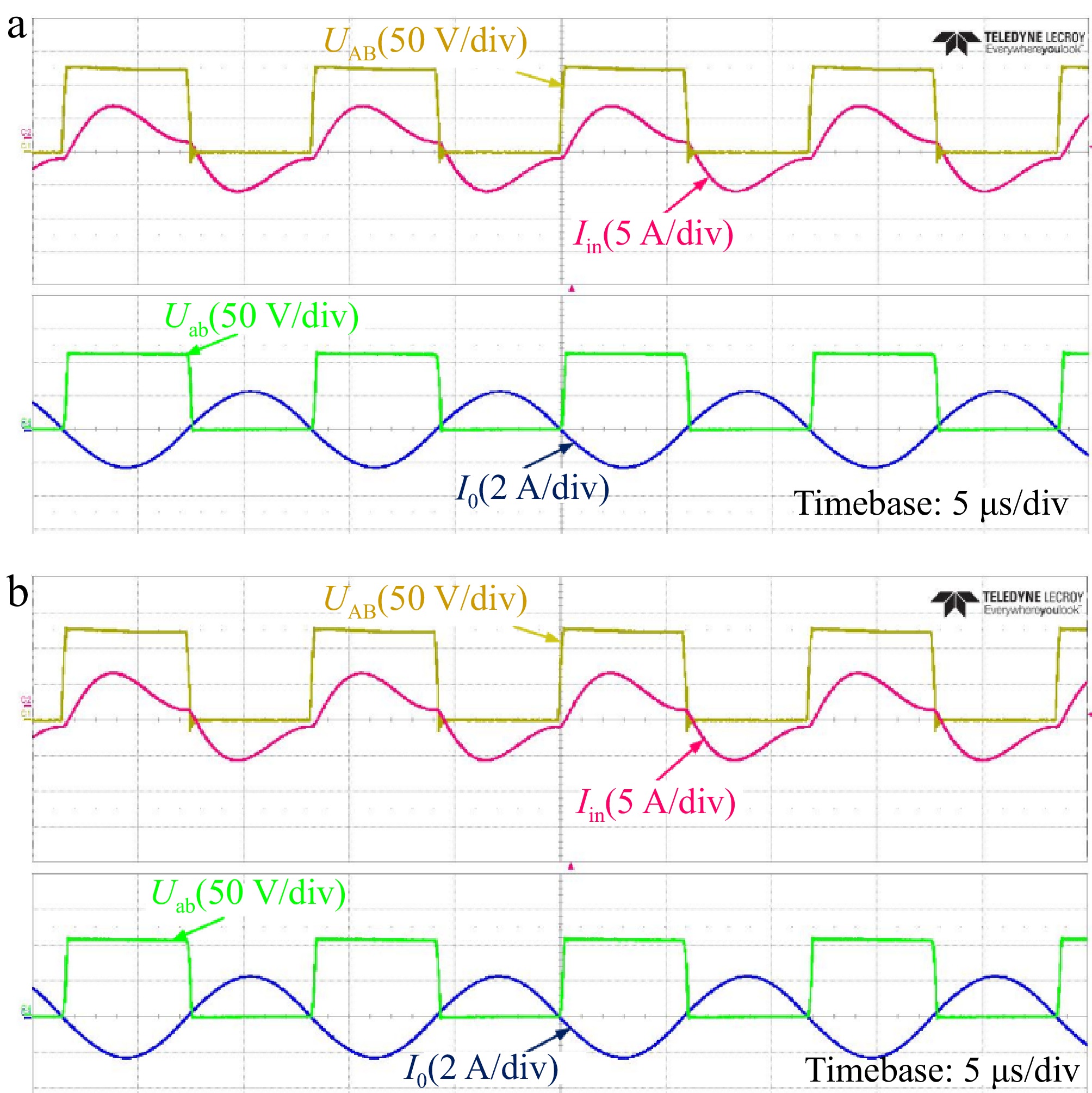
Figure 20.
Experimental waveforms of alignment and misalignment conditions in CV mode. (a) Alignment condition. (b) Misalignment condition.
-
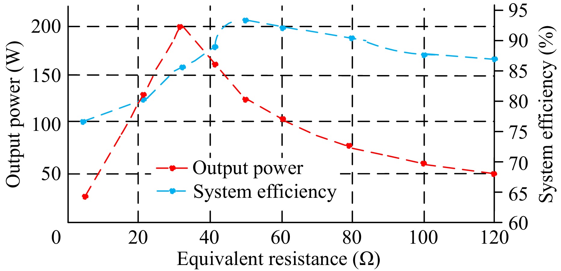
Figure 21.
Efficiency and output power of the proposed IPT system.
-
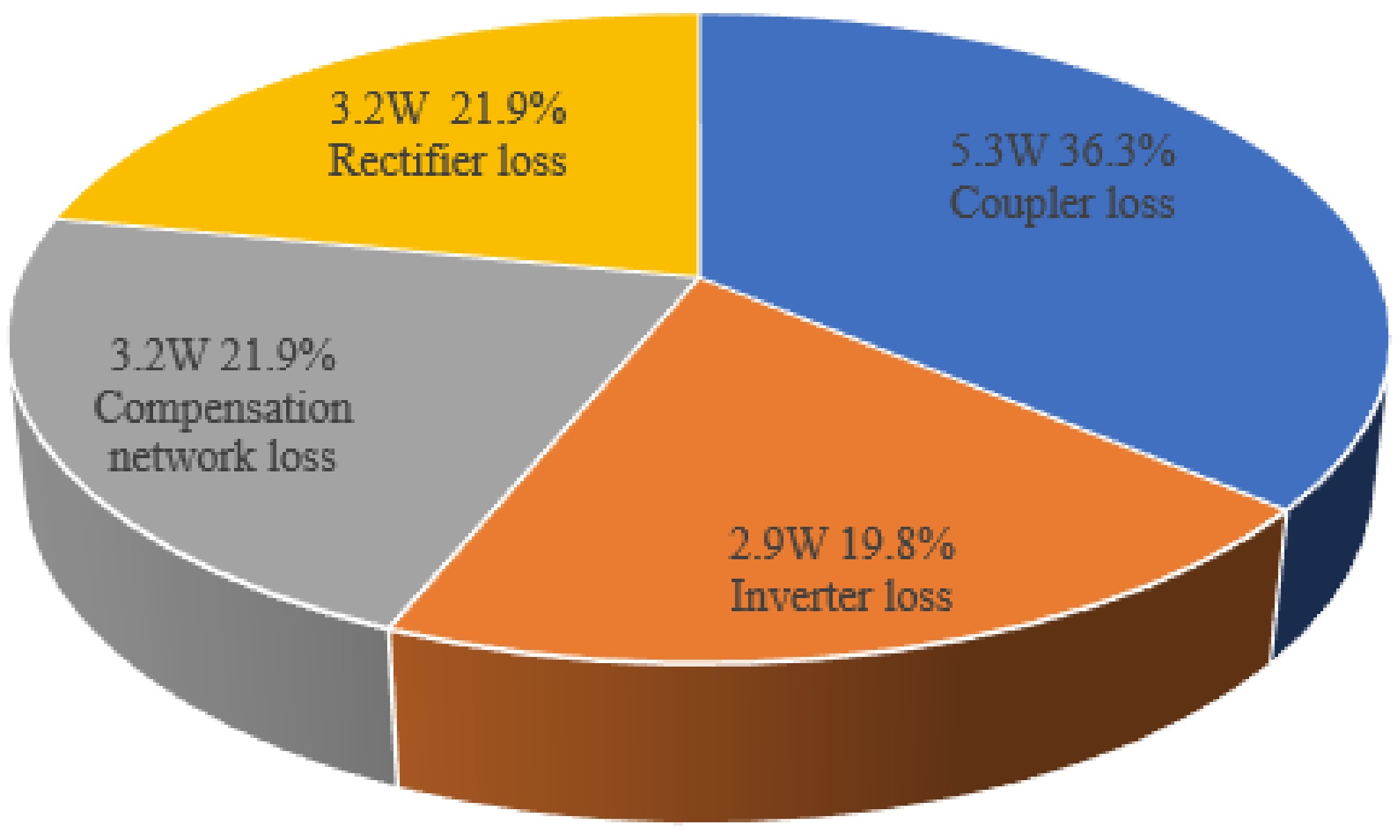
Figure 22.
Efficiency distribution of the proposed IPT system.
-
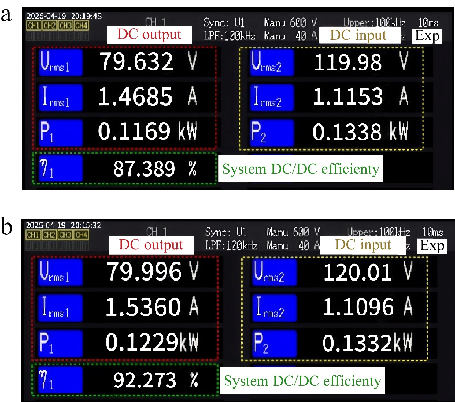
Figure 23.
Power analyzer data in the CV mode. (a) Misaligned state. (b) Aligned state.
-
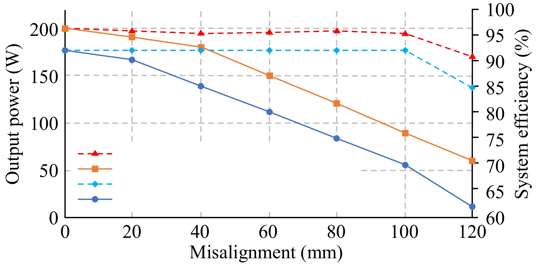
Figure 24.
Output power and efficiency comparison between third-coil and two-coil coupler with misalignment.
-
Symbols Parameters Values UDC-link DC-link input voltage 120 V fo Resonant frequency 85 kHz Po Rate output power 200 W Uo Battery charging voltage 80 V Io Battery charging current 2.5 A k Coupling coefficient 0.073~0.122 LP Primary coil inductance 250.9 μH LS Secondary coil 161.1 μH LT Third coil 106.1 μH MPT MI between LP and LT 16.69 μH MPS MI between LP and LS 27.85 μH MTS MI between LT and LS 87.1 μH RLp Transmitting-coil AC resistance of Lp 221.03 mΩ RLs Transmitting-coil AC resistance of Ls 153.26 mΩ RLT Receiving-coil AC resistance of LT 37.75 mΩ RL1 Resistance of inductance L1 50.8 mΩ RL2 Resistance of inductance L2 62.9 mΩ RCp1 Resistance of capacitor Cp1 13.3 mΩ RCp2 Resistance of capacitor Cp2 13.7 mΩ RCf1 Resistance of capacitor Cf1 5.4 mΩ RCf2 Resistance of capacitor Cf2 4.8 mΩ rCF Turn ON-state resistance of the diodes 4.6 mΩ Rds(on) The drain-source on-state resistance 39 mΩ Table 1.
Essential system parameters of proposed IPT system.
-
Parameter Value L1 16.54 μH L2 16.53 μH CP1 212 nF Cf1 13.97 nF CP2 212 nF Cf2 45.85 nF Table 2.
Parameters of the resonant network.
-
Symbol Parameter value LP Length × width 240 mm × 240 mm LT Length × width 160 mm × 160 mm LS Length × width 250 mm × 250 mm Dd Inside radius (LS) 50 mm nP Turns (LP) 27 nS Turns (LS) 18 nT Turns (LT) 16 R(P) Transmitting coil dimension 240 mm × 240 mm × 2.5 mm R(S) Receiving coil dimension 250 mm × 240 mm × 5 mm Table 3.
Essential parameters of the proposed coils.
-
Inductor/
capacitor countsSwitch counts Coils of LCT Misalignment tolerance
X-directionMisalignment tolerance Y-direction Output characteristic Efficiency Max. power Ref. 2/6 4 4 37% 37% CP 85.5%−93.1% 700 W [23] 1/3 4 3 50% 50% CC/CV 88.2%−92.5% 460 W [24] 1/3 4 3 50% 50% CC 76%−84% 200 W [25] 4/6 6 4 50% 12.5% CC/CV 85.7%−93.9% 1 kW [26] 2/6 4 4 37.5% 37.5% CV 87%−93.9% 3.5 kW [27] 1/3 4 2 50% 50% CV 81%−88% 700 W [28] 2/4 4 3 40% 40% CC 92% 3.4 kW [29] 2/4 4 3 50% 50% CC 80.6% 100 W [30] 2/4 4 + 3 3 42% 42% CC/CV 86.5%−92.9% 200 W This work Table 4.
Comparison with other methods reported in the literature.
Figures
(24)
Tables
(4)