-
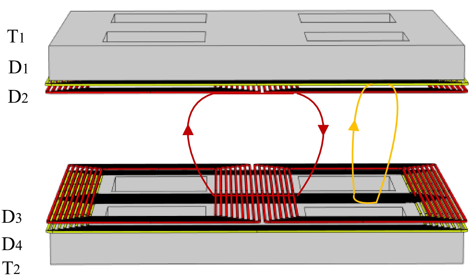
Figure 1.
Magnetic field diagram of the DVDD magnetic coupling mechanism.
-
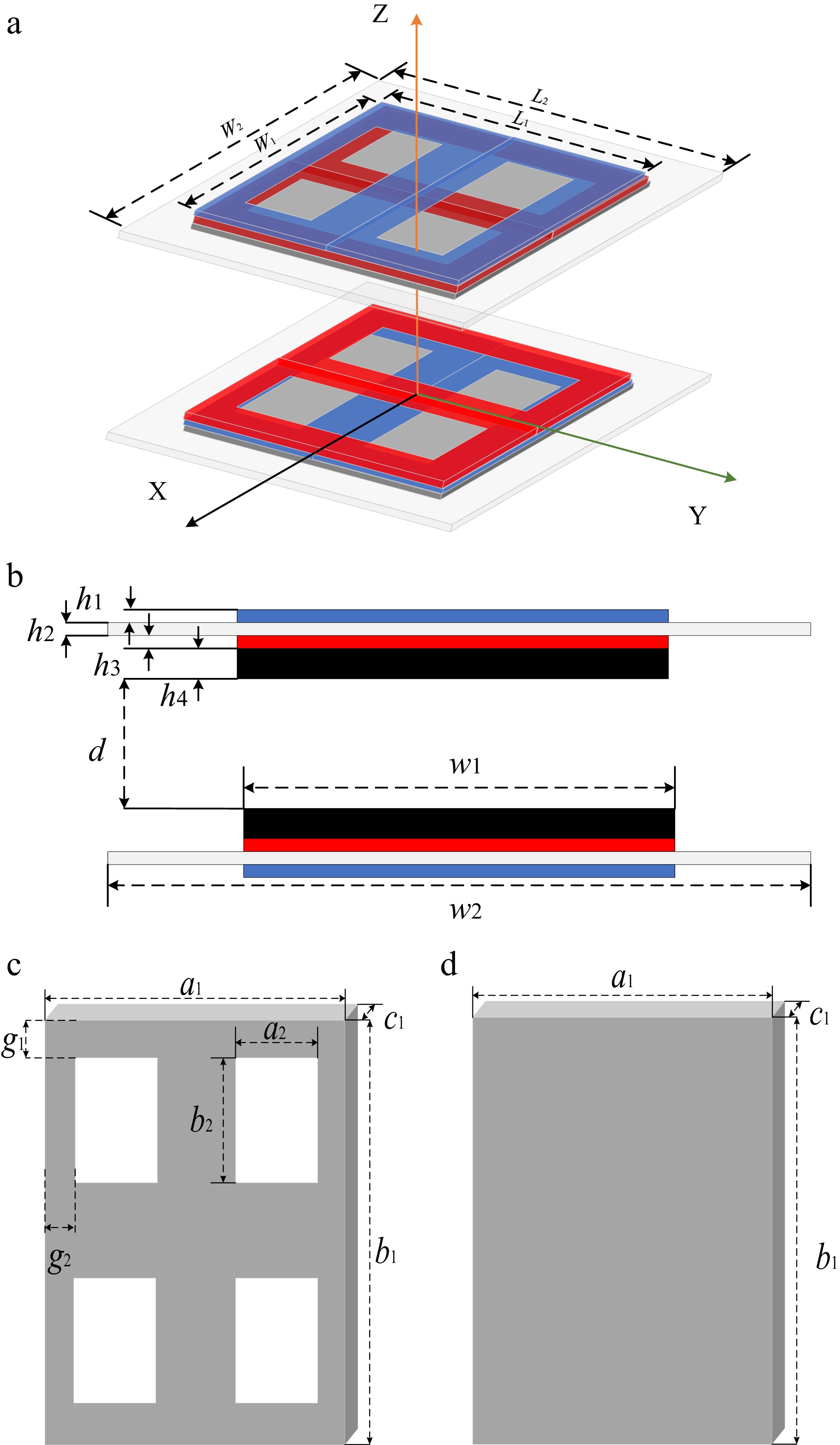
Figure 2.
Schematic diagram of the DVDD magnetic coupling mechanism. (a) 3D model of the DVDD magnetic coupling mechanism. (b) Front view of the DVDD magnetic coupling mechanism. (c) New-type magnetic core structure. (d) Full-coverage magnetic core structure.
-
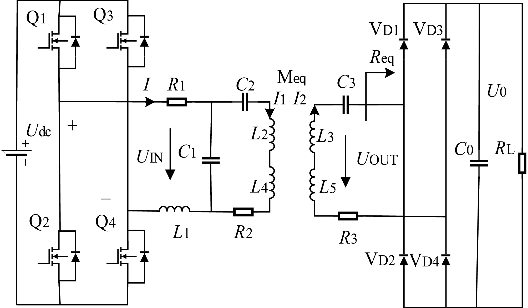
Figure 3.
Circuit diagram of a wireless power transfer system based on the DVDD magnetic coupling mechanism.
-
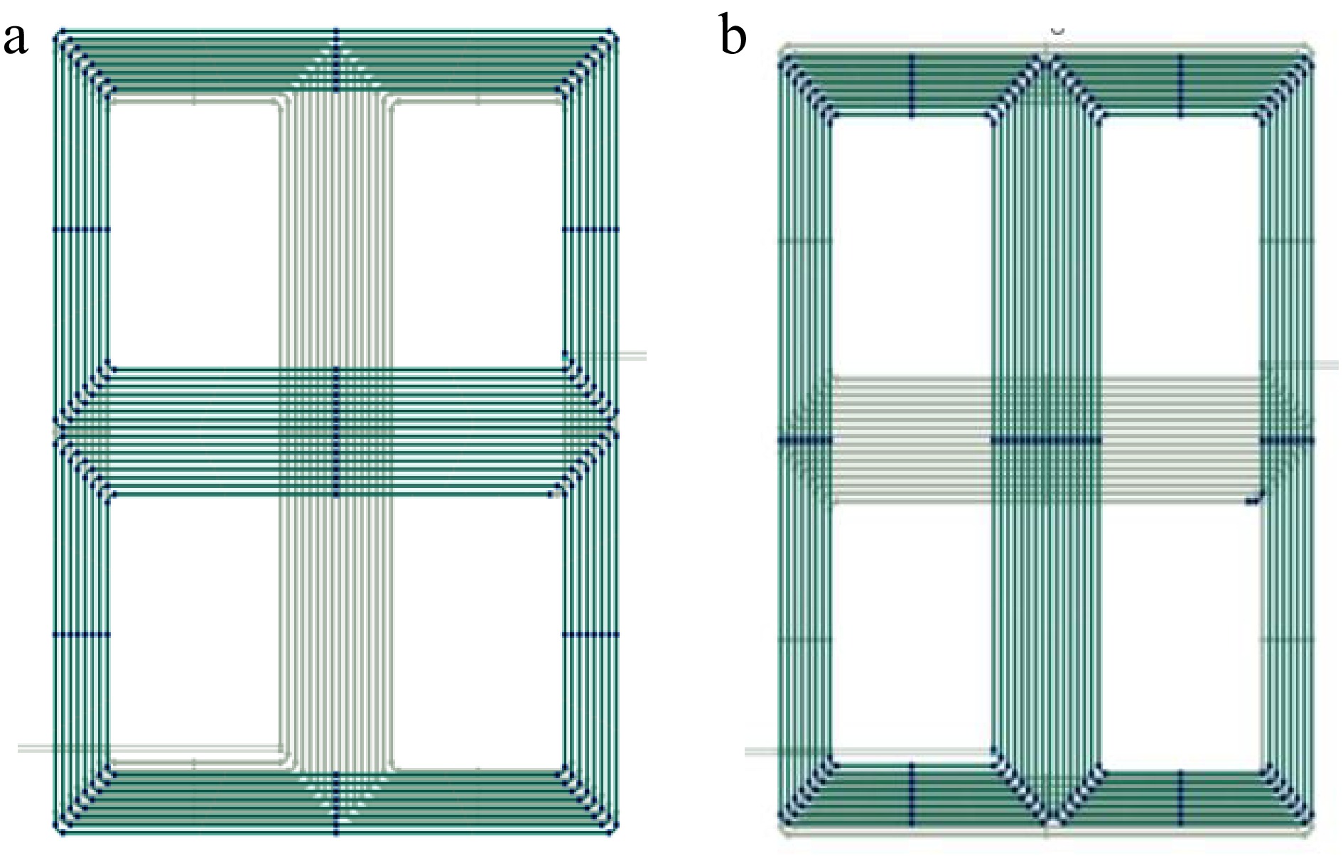
Figure 4.
Simulation model of DVDD coil in COMSOL. Schematic diagram of the (a) coil front view and (b) coil rear view.
-
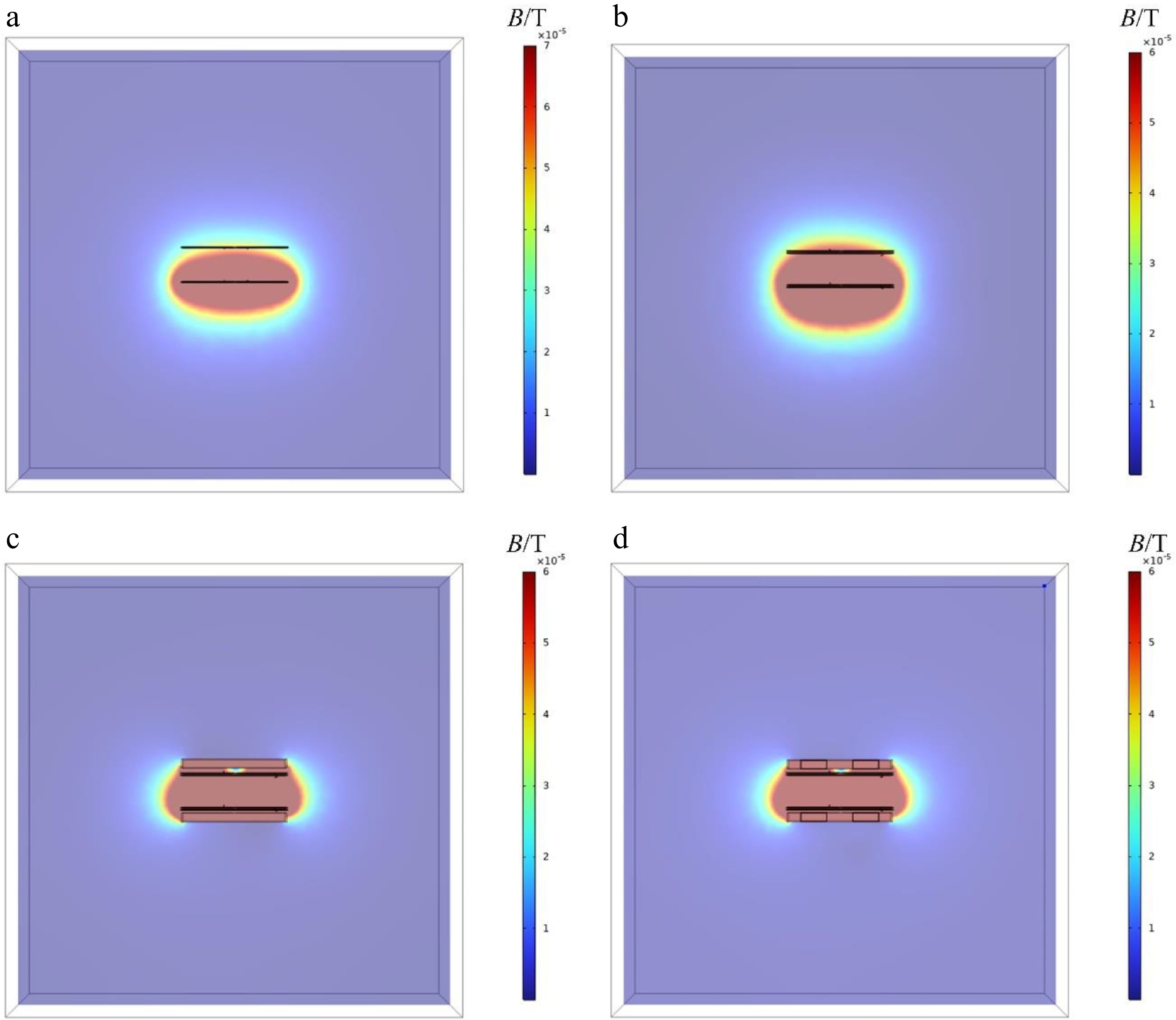
Figure 5.
Magnetic field contour plots of the XZ cross-section of the magnetic coupling mechanism under four scenarios. (a) Single DD magnetic coupling mechanism without magnetic core. DVDD magnetic coupling mechanism (b) without magnetic core, (c) with full-cover magnetic core, and (d) with new-type magnetic core.
-
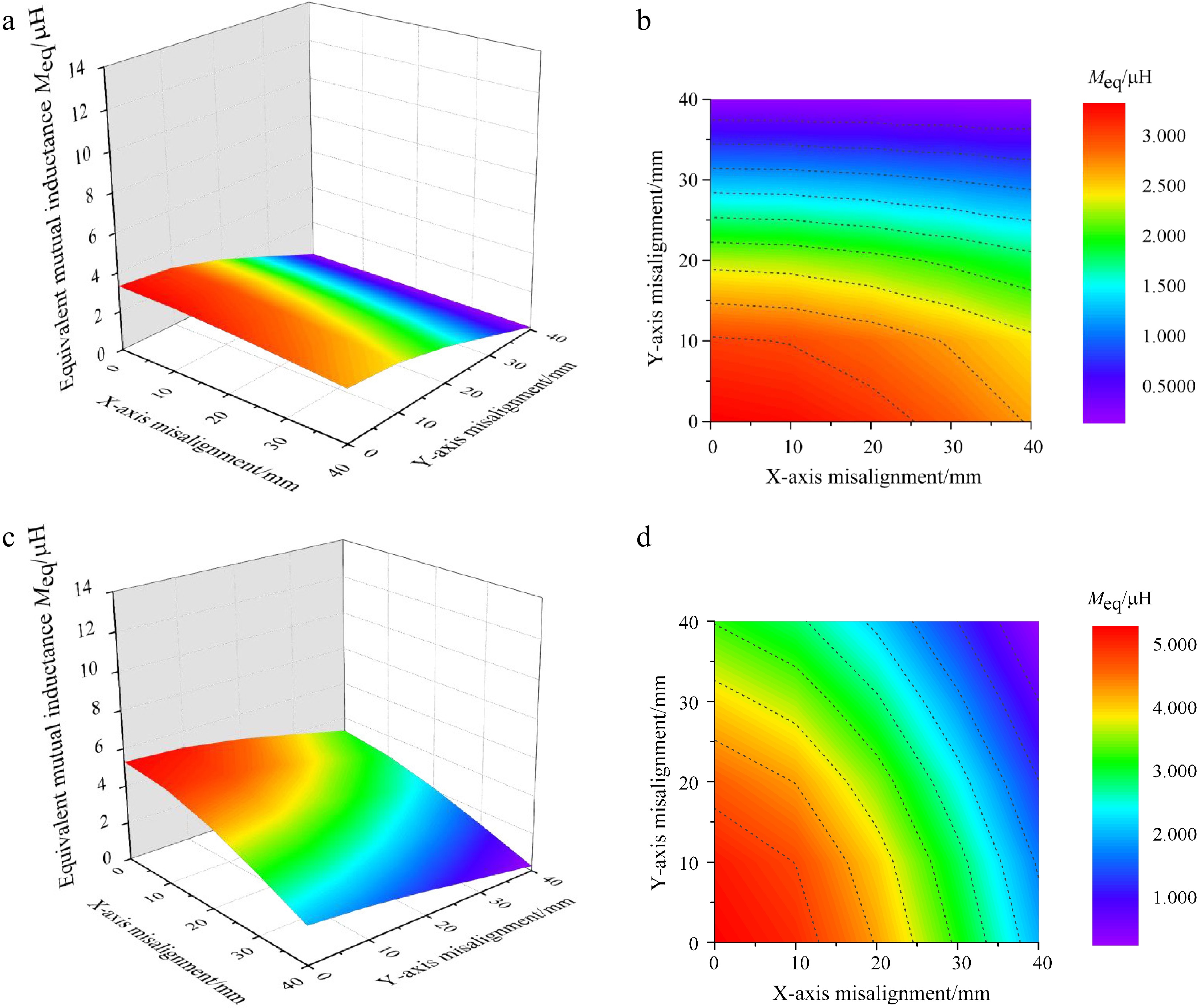
Figure 6.
Mutual inductance variation contour plots of two magnetic coupling mechanisms under misalignment conditions. (a) 3D diagram of the mutual inductance variation for single DD magnetic Coupling mechanism without magnetic core. (b) Front view of mutual inductance variation for single DD magnetic coupling mechanism without magnetic core. (c) 3D diagram of mutual inductance variation for DVDD magnetic coupling mechanism without magnetic core. (d) Front view of mutual inductance variation for DVDD magnetic coupling mechanism without magnetic core.
-
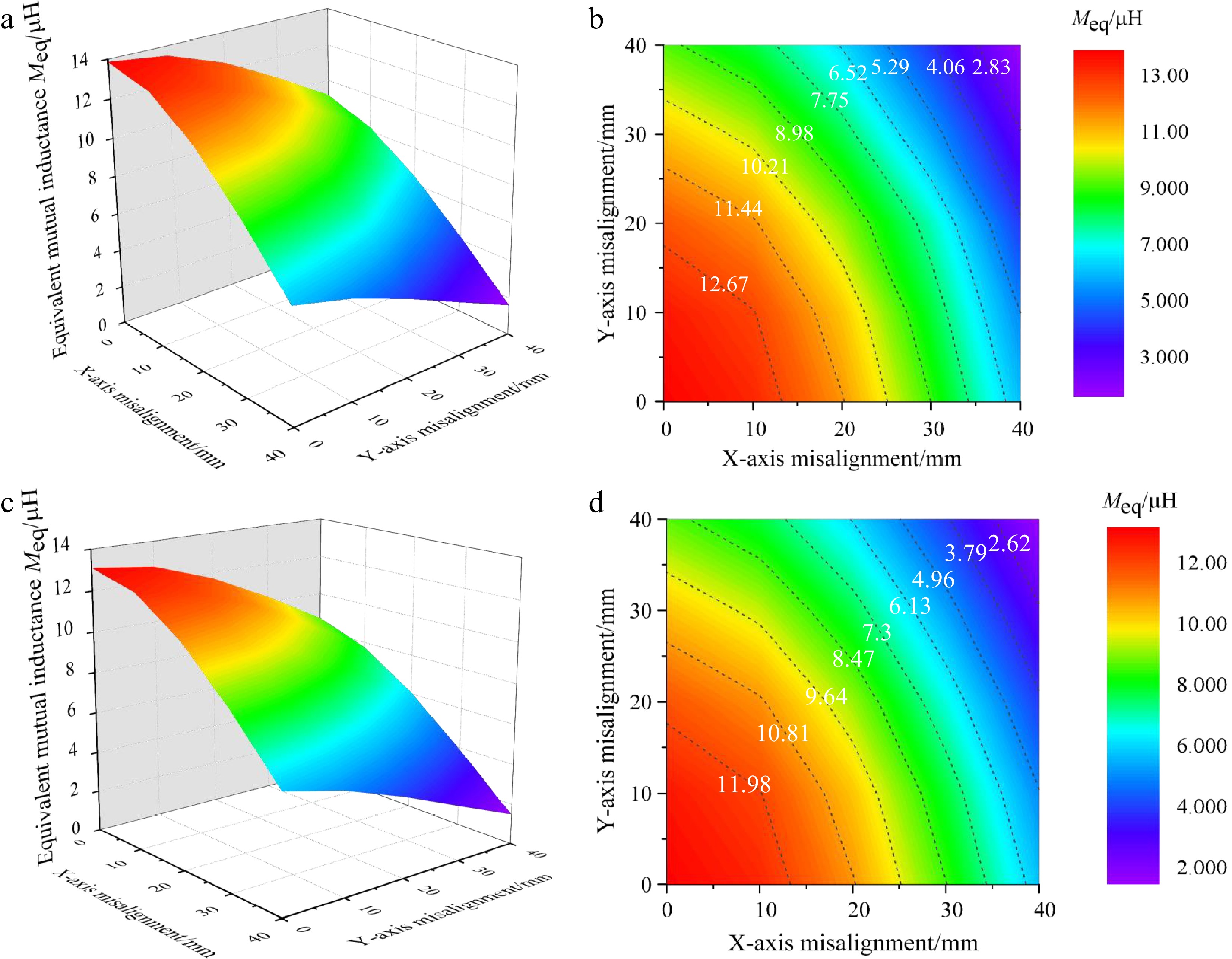
Figure 7.
Mutual inductance variation contour plots of two magnetic cores under misalignment conditions. (a) 3D diagram of the mutual inductance variation for DVDD magnetic coupling mechanism with full-coverage magnetic core. (b) Front view of the mutual inductance variation for DVDD magnetic coupling mechanism with full-coverage magnetic core. (c) 3D view of mutual inductance variation for DVDD magnetic coupling mechanism with new-style magnetic core. (d) 3D diagram of mutual inductance variation for DVDD magnetic coupling mechanism with new-type magnetic core.
-
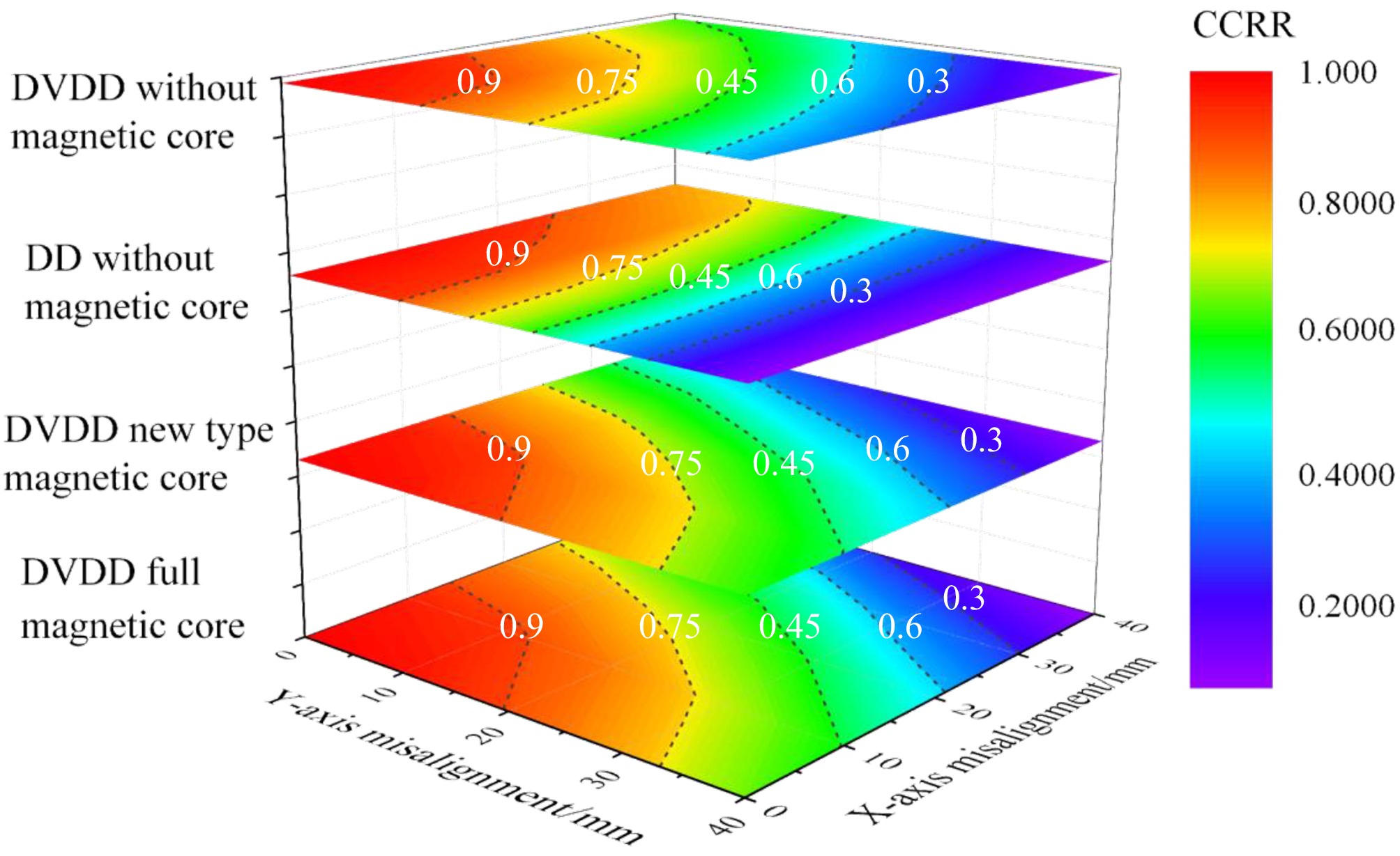
Figure 8.
Impact of X/Y misalignment on CCRR in four cases.
-
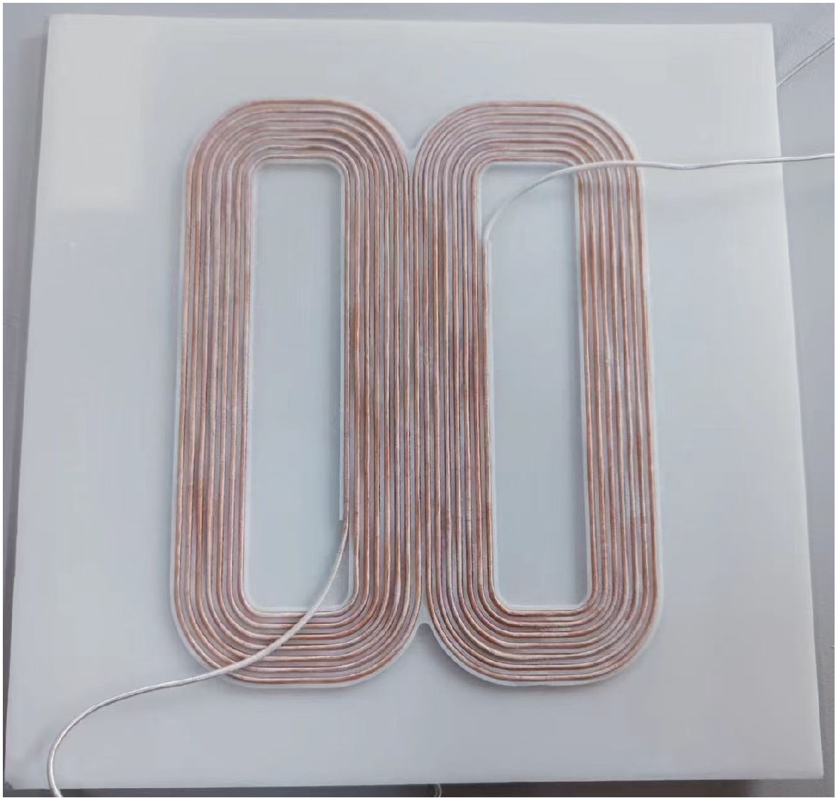
Figure 9.
Physical schematic of the DVDD coil.
-
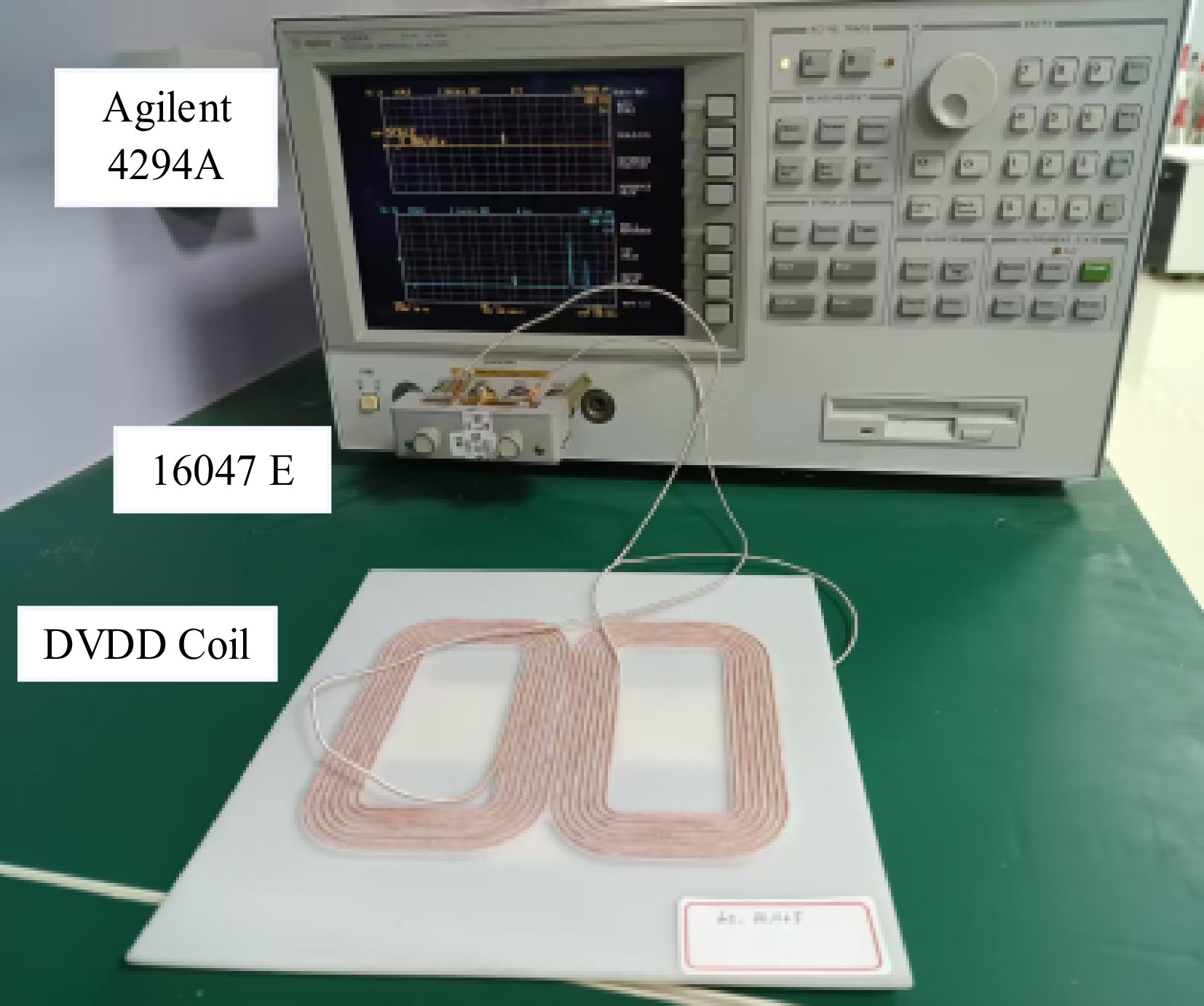
Figure 10.
DVDD coil inductance parameter testing platform.
-
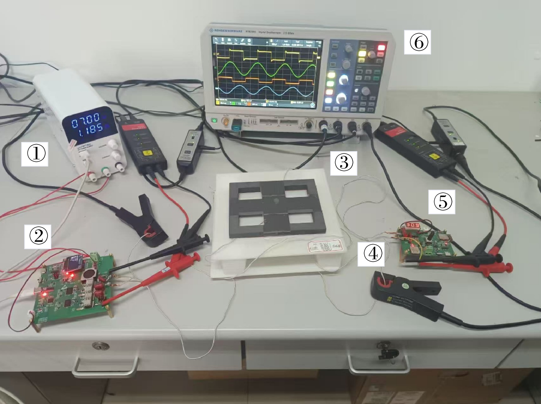
Figure 11.
Experimental platform of the WPT system based on the DVDD magnetic coupling mechanism
-
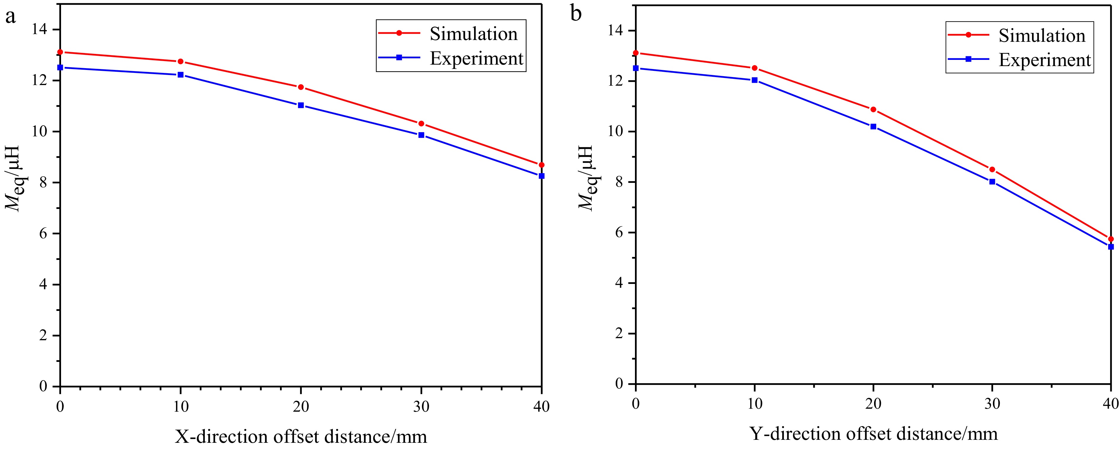
Figure 12.
Mutual inductance variation curve of DVDD magnetic coupling mechanism under X-axis and Y-axis direction misalignment. Mutual inductance change curve under (a) X-axis direction misalignment and (b) Y-axis direction misalignment.
-
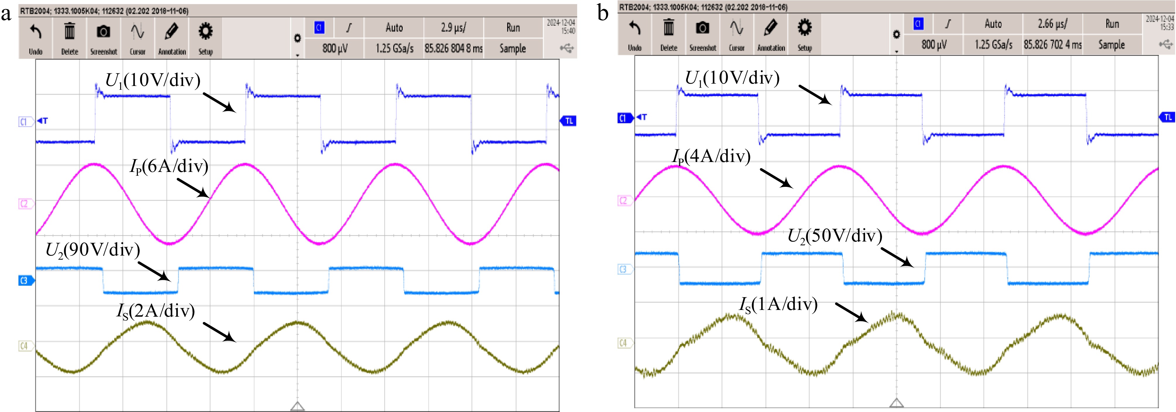
Figure 13.
Experimental waveforms. Waveform diagram under (a) magnetic coupling alignment and (b) 4 cm misalignment of magnetic coupling mechanism.
-
Parameters Values (mm) Parameters Values (mm) W1 120 a1 120 W2 200 a2 30 L1 150 b1 150 L2 200 b2 40 h1 1.53 g1 15 h2 2 g2 12 h3 1.53 c1 10 h4 10 Table 1.
Relevant parameters of the DVDD magnetic coupling mechanism.
-
Parameters Values Parameters Values L1 2.2 μH C1 1.15 μF LS 47.586 μH C2 51.88 nF LP 50.866 μH C3 53.285 nF Udc 7 V f 100 kHz RL 20 Ω Table 2.
Main circuit parameters of the wireless power transfer system.
Figures
(13)
Tables
(2)