-
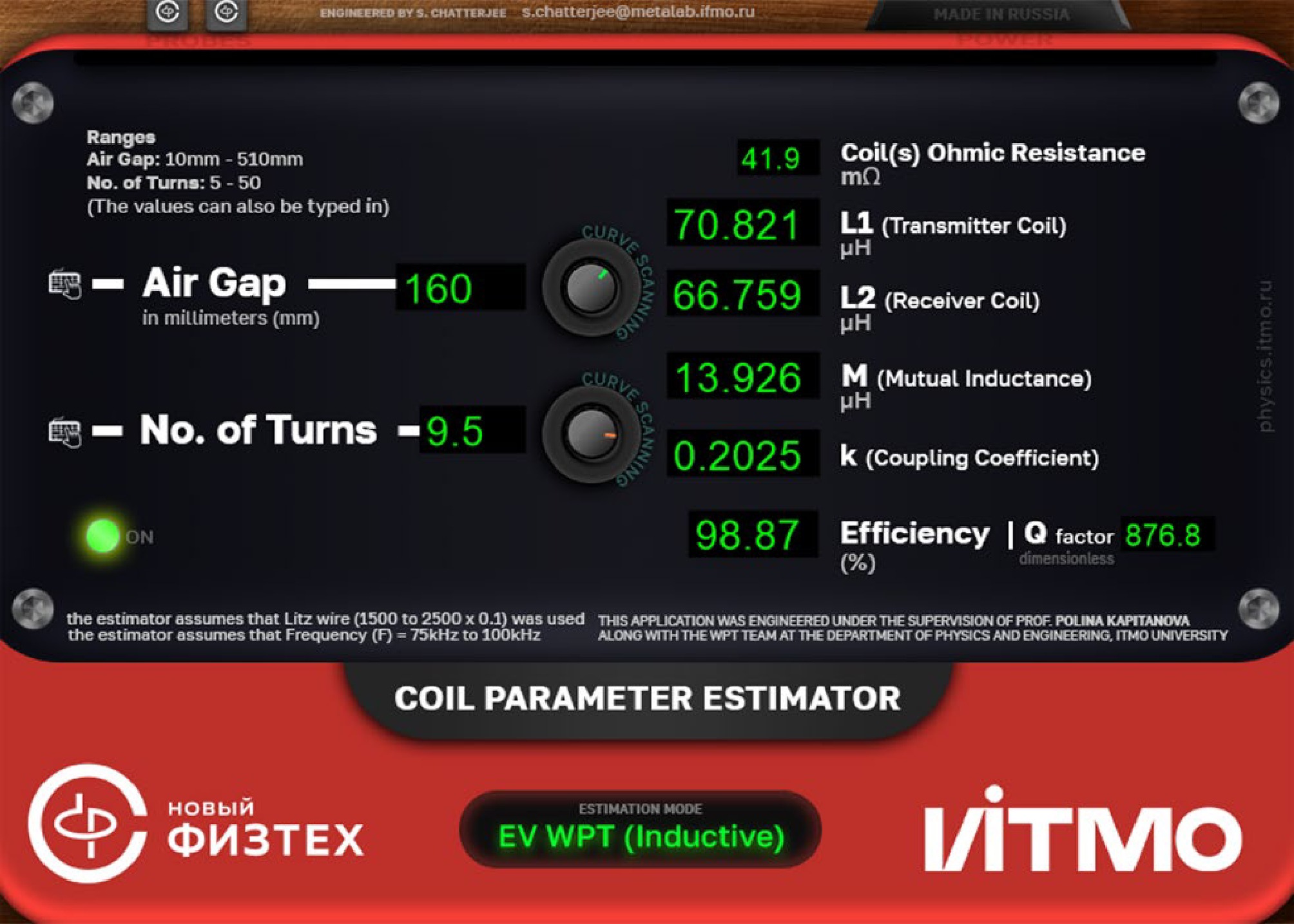
Figure 1.
GUI of the standalone version of the real-time estimator of the parameters for coupled coils in an 11-kW wireless charging system.
-
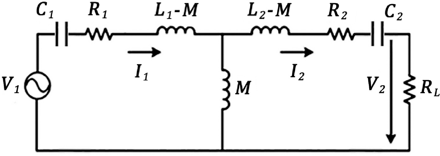
Figure 2.
Equivalent circuit of the electromagnetic section of the IPT system.
-
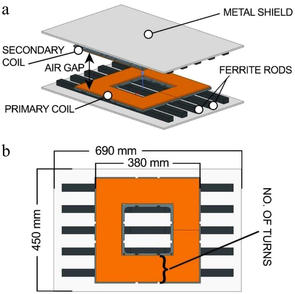
Figure 3.
3D FEM model of the IPT system under consideration.
-
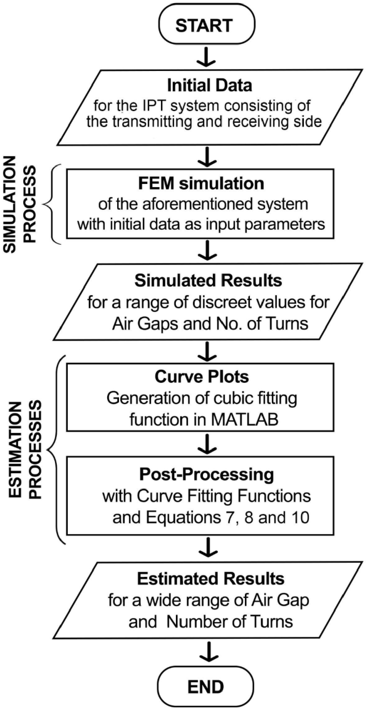
Figure 4.
Flowchart of the simulation and estimation processes.
-
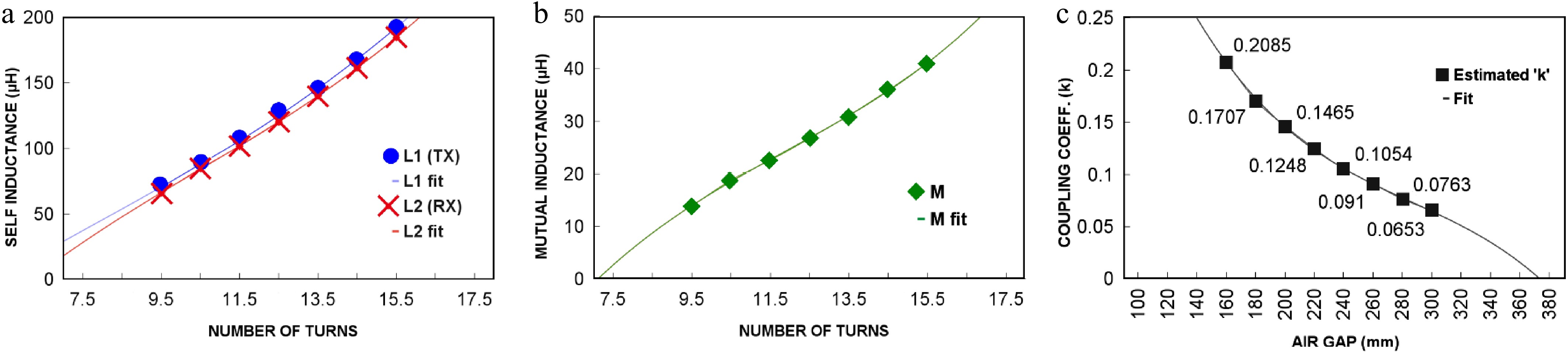
Figure 5.
Relationships among the crucial parameters: (a) relationship between the self-inductance of individual coils and the number of turns, (b) relationship between mutual inductance and the number of turns, and (c) relationship between the coupling coefficient and the air gap.
-
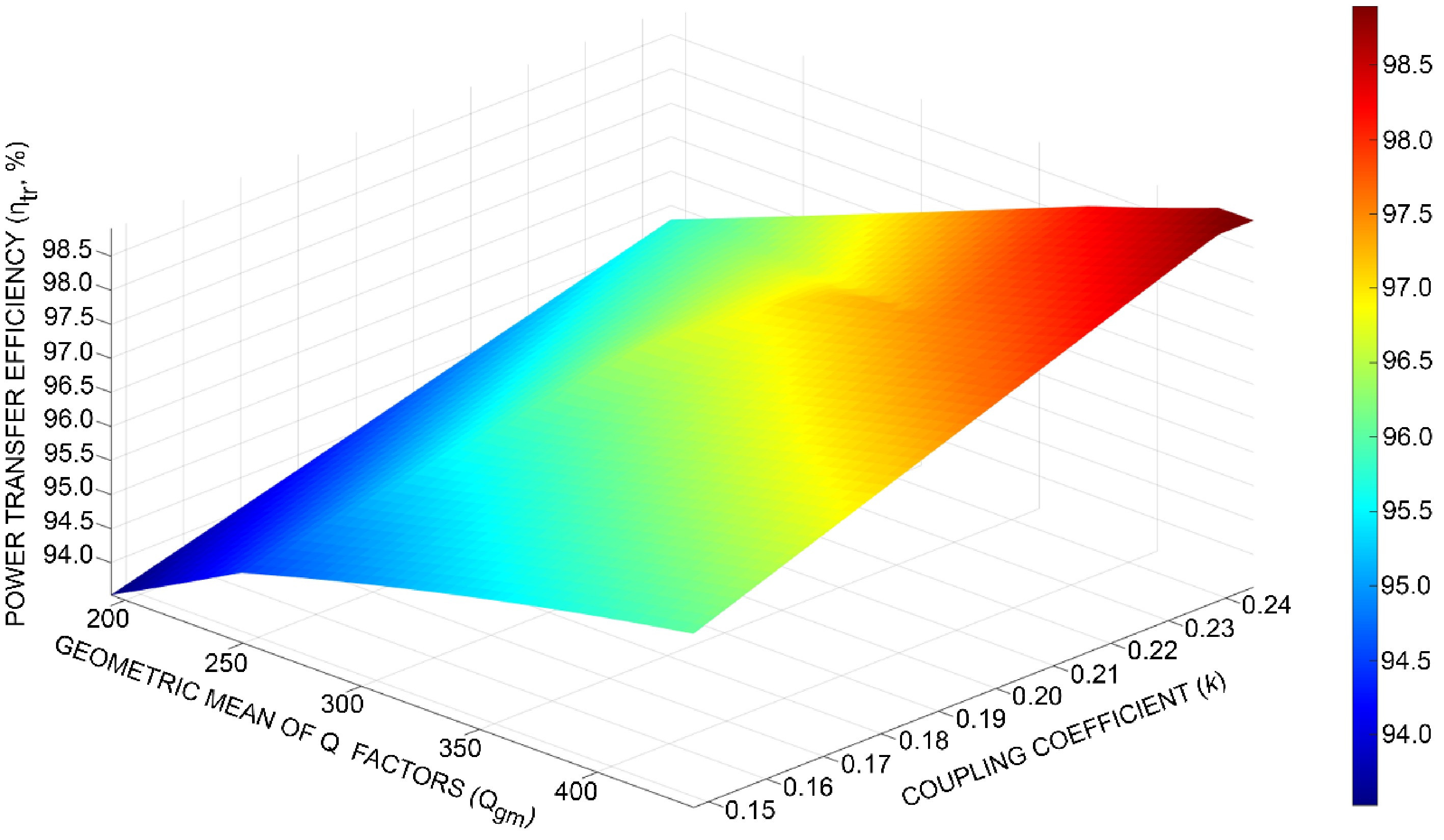
Figure 6.
Power transfer efficiency
$ {(\eta }_{\mathrm{t}\mathrm{r}}) $ $ \text{(}{Q}_{\mathrm{g}\mathrm{m}}) $ $ \text{(}k) $ -
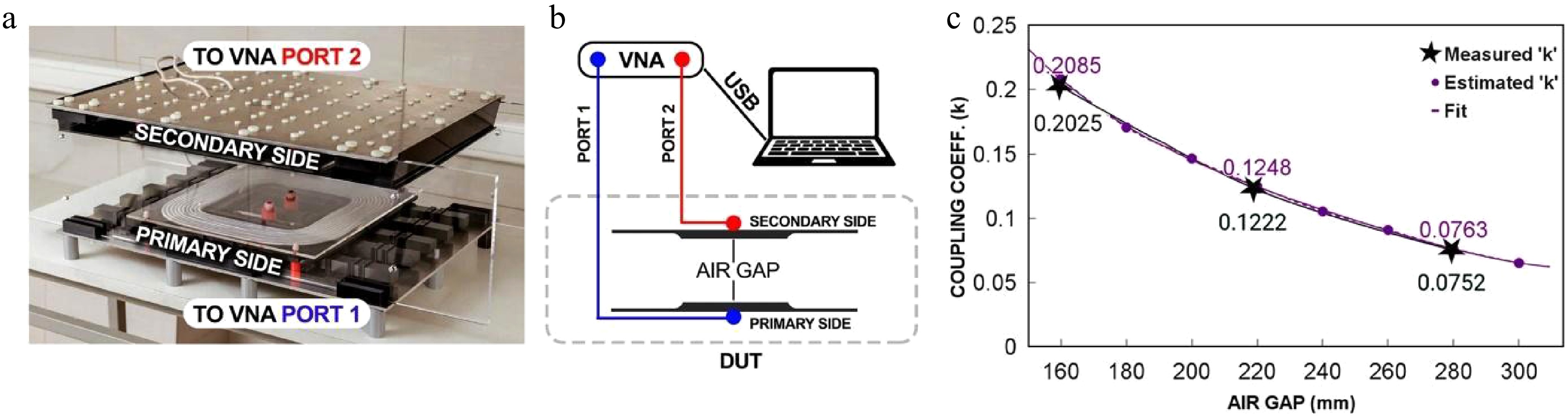
Figure 7.
(a) Photograph of the laboratory prototype of an 11- kW IPT system for EVs. (b) Schematic diagram of the experimental setup. (c) Measured and estimated dependence of the coupling coefficient as a function of the air gap between the transmitting and receiving sides of the 11-kW IPT system.
-
Initial data Value Dimensions (metal screen) 450 mm × 690 mm × 5 mm Dimensions (coil) 380 mm × 380 mm × 5 mm Dimensions (ferrite) 126 mm × 28 mm × 20 mm (25 pieces) No. of turns 9.5, 10.5, ... 15.5 Air gap (mm) 160, 180, ... 300 Metal screen material Aluminum Coil material Copper (Litz wire, 0.1 mm × 2,500 strands) Ferrite material Manganese–zinc (N87) Frequency 85 kHz Boundary conditions Tangential fields (50% padding on all sides) Solver type Eddy current solver (low frequency) Output Discrete data table Table 1.
Initial data provided for 3D FEM simulation of the IPT system.
-
x (mm) Z11 L1 (μH) Z22 L2 (μH) Z21 M (μH) 160 0.019 + 38.61i 72.3 0.032 + 38.19i 71.5 0.51 + 7.77i 14.56 220 0.021 + 38.18i 71.4 0.028 + 37.43i 70.1 0.37 + 4.62i 8.65 280 0.027 + 37.46i 70.1 0.026 + 37.26i 69.9 0.14 + 2.81i 5.26 Table 2.
Measured Z-parameters and the calculated values of L1, L2 and M for different air gaps.
-
x (mm) k (estimated) k (measured) Error (%) 160 0.2085 0.2025 2.9% 180 0.1707 − − 200 0.1465 − − 220 0.1248 0.1222 2.1% 240 0.1054 − − 260 0.091 − − 280 0.0763 0.0752 1.4% 300 0.0653 − − Table 3.
Estimated and measured values of the coupling coefficient for different air gaps between the primary and secondary coils.
Figures
(7)
Tables
(3)