


-
Wireless Power Transfer technology, characterized by its non-contact and convenient features, has broad application prospects in the field of electric vehicle charging[1−4]. In the wireless charging system for electric vehicles, the transmitting coil is placed on the ground, while the receiving coil is mounted on the bottom of the vehicle. When the wireless charging system is in operation, there is a magnetic field coupling area between the transmitting coil and the receiving coil, where metal foreign objects, such as coins and cans, can easily fall, resulting in a decrease in transmission efficiency of the system and even possibly causing a series of safety issues such as fire. Therefore, metal foreign object detection must be carried out for the wireless charging system to ensure sufficient safety of the electric vehicle wireless charging system[5].
Currently, the main methods for foreign object detection in the wireless charging systems of electric vehicles include system circuit parameter-based foreign object detection, machine vision-based non-electrical parameter foreign object detection, and auxiliary coil-based foreign object detection. The system circuit parameter-based foreign object detection method primarily examines certain circuit parameters such as voltage, inductance, quality factor, and mutual inductance, utilizing changes in these parameters to determine the presence of foreign metal objects in the system[6−12]. A non-ferromagnetic metal foreign object detection method based on the equivalent quality factor, which defines the voltage ratio in the system's equivalent circuit after removing the pickup end as the equivalent quality factor, both simulations and experiments demonstrate that when metal foreign objects enter the electromagnetic coupling mechanism, the equivalent quality factor experiences a significant decrease, enabling the detection of non-ferromagnetic metals[13].
The machine vision-based non-electrical parameter foreign object detection method utilizes cameras to capture images of the surface of the transmitting coil, enabling automated detection and identification of foreign objects. A machine learning-based foreign object detection algorithm that employs the YOLOv5 object detection algorithm to simultaneously detect metal objects and biological entities[14]. The detection principle of the foreign object detection method based on additional auxiliary coils is that when metal foreign objects approach the detection coils, the electrical parameters such as voltage and inductance of the detection coils change, allowing for the detection of metal foreign objects. This method can be divided into active and passive auxiliary coils. Active auxiliary coils can detect independently of the wireless charging system for electric vehicles, whereas passive auxiliary coils rely on the wireless charging system itself. An active metal foreign object detection scheme based on impedance changes, which applies an excitation source to the added detection coil array and observes and analyzes the resonance frequency of the detection coils to detect different types of metal foreign objects[15]. An array-type differential coil detection structure that achieves metal foreign object detection by monitoring changes in the output voltage of the detection coils. This detection coil structure has minimal impact on system power and high detection accuracy[16].
The metal foreign object detection technique relying on machine vision can be easily disturbed by external factors, while the method using auxiliary coils falls short in detecting metal objects before the charging process begins for electric vehicles. To tackle these challenges and bolster the safety of electric vehicle wireless charging systems, this paper introduces a collaborative optimization strategy for metal foreign object detection that seamlessly combines machine vision and auxiliary coils. Ultimately, simulations confirm the effectiveness of the proposed method in detecting metal foreign objects.
-
When the electric vehicle wireless charging system is working normally, there is a magnetic field coupling area between the primary transmitting coil and the secondary receiving coil, where various foreign objects may enter. Among them, metal foreign objects have the greatest impact on the safety and normal operation of the wireless charging system[17,18]. Under the action of the high-frequency electromagnetic field in the magnetic field coupling area of the electric vehicle wireless charging system, metal foreign objects will produce a series of electromagnetic phenomena. According to the different magnetic permeabilities, metal foreign objects can be divided into ferromagnetic metal foreign objects and non-ferromagnetic metal foreign objects.
When there is a non-ferromagnetic metal foreign object between the transmitting coil and the receiving coil, due to the phenomenon of electromagnetic induction, the metal foreign object placed in the alternating magnetic field of the transmitting coil will generate eddy currents. Since the metal foreign object has a certain resistance value, the eddy currents flowing through the resistance will generate heat, which is known as eddy current loss.
$ {P_e} \propto \dfrac{{B_m^2{f^2}}}{\rho } $ (1) where, Pe (W) represents the eddy current loss generated by the metal foreign object, ρ (Ω·m) is the resistivity of the metal foreign object, Bm (T) is the maximum magnetic flux density of the coil, and f (Hz) is the frequency of the alternating magnetic field in the wireless charging system.
Ferromagnetic metals can conduct both electricity and magnetism, and in an electromagnetic field, they exhibit both magnetic and eddy current effects. When there is a ferromagnetic metal foreign object between the transmitting coil and the receiving coil, the energy loss per unit volume of the metal foreign object is proportional to the area enclosed by the hysteresis loop, which is known as the magnetic effect. The formula for calculating the magnetic effect is:
$ {P_h} = \eta fB_m^{1.6} $ (2) where, Ph (W) represents the hysteresis loss generated by the metal foreign object, f (Hz) is the frequency of the alternating magnetic field, Bm (T) is the maximum magnetic flux density on the hysteresis loop, and η is the coefficient of hysteresis loss.
In this paper, iron is selected as the representative of metal foreign objects, and the finite element analysis software COMSOL is used to model the entry of metal foreign objects into the electromagnetic coupling mechanism, to analyze the influence characteristics of metal foreign objects on the wireless charging system, thereby proving the necessity of metal foreign object detection. Table 1 shows the simulation parameters of the electromagnetic coupling mechanism.
Table 1. Simulation parameters of the electromagnetic coupling mechanism.
Parameters Values Primary coil size (mm) 580 × 420 Primary coil wire diameter (mm) 5 Number of turns of primary coil 15 Secondary coil size (mm) 320 × 320 Secondary coil wire diameter (mm) 5 Number of turns of secondary coil 15 Iron material dimensions (mm) 150 × 100 × 80 Distance between primary and secondary coils (mm) 150 Current (A) 100 Figure 1a shows the simulation model of the electromagnetic coupling mechanism in the absence of foreign objects, while Fig. 1b depicts the simulation model of the electromagnetic coupling mechanism in the presence of metal foreign objects. By comparing Fig. 1a with Fig. 1b, it can be observed that darker colors represent higher magnetic field intensities. The maximum magnetic field intensity of the system decreases from 20.6 to 18.8 mT, while the minimum magnetic field intensity drops from 0.14 mT to 5.89 × 10⁻⁴ mT. This indicates that metal foreign objects weaken the magnetic field intensity of the system.
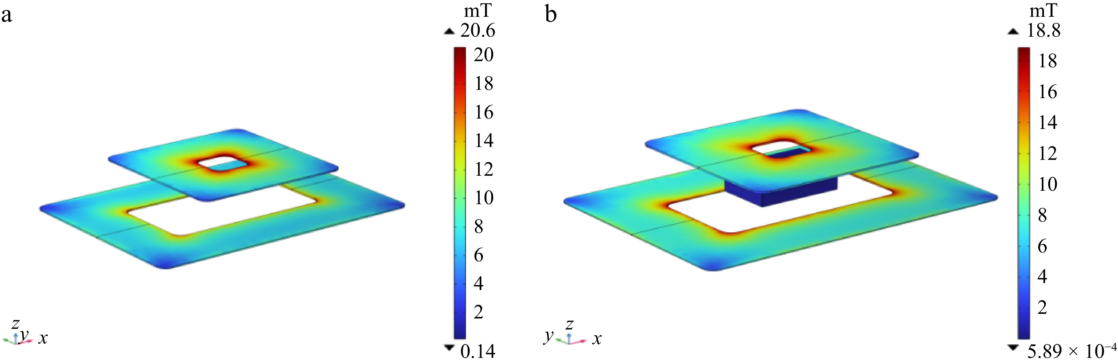
Figure 1.
The simulation model of the electromagnetic coupling mechanism: (a) in the absence of foreign objects, (b) in the presence of foreign objects.
Figure 2a shows the magnetic field intensity distribution of the receiving coil in the absence of foreign objects, while Fig. 2b represents the magnetic field intensity distribution of the receiving coil in the presence of foreign objects. The arrows represent the magnetic induction intensity lines. The selected iron material metal foreign object, upon entering the electromagnetic coupling mechanism, exhibits both eddy current and magnetic effects. The eddy current effect weakens the external magnetic field, while the magnetic effect enhances the external magnetic field. By comparing Fig. 2a and Fig. 2b, it can be observed that the maximum magnetic field intensity decreases from 16.5 to 15.7 mT, while the minimum magnetic field intensity drops from 0.13 to 0.12 mT. This indicates that the iron material metal foreign object selected in this paper weakens the magnetic field intensity of the receiving coil, thereby reducing the working efficiency of the wireless charging system.
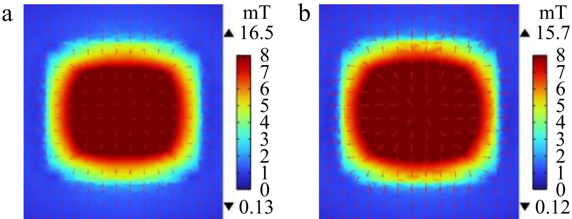
Figure 2.
Magnetic field intensity of the receiving coil: (a) in the state without foreign objects, (b) in the state with foreign objects.
Design of a metal foreign body detection scheme
-
This paper introduces a metal foreign object detection method for wireless charging systems, which leverages a collaborative optimization strategy combining machine vision and auxiliary coils. Before initiating the charging of electric vehicles, an enhanced machine vision detection technique based on the YOLOv8 model scans the charging area for metal foreign objects. If any are found, they must be removed before proceeding with charging. If the area is clear, the wireless charging system begins operation. While charging, a dual approach is adopted, integrating machine vision with an auxiliary coil detection method. If metal foreign objects are detected during charging, the process is immediately halted until the objects are removed, ensuring both charging efficiency and system safety. The proposed detection method addresses the challenge of metal foreign object detection in wireless charging systems by offering a complementary solution that transcends the limitations of individual methods, thereby enhancing adaptability to diverse environments and boosting detection accuracy. The detection process of the method presented in this paper is illustrated in Fig. 3.
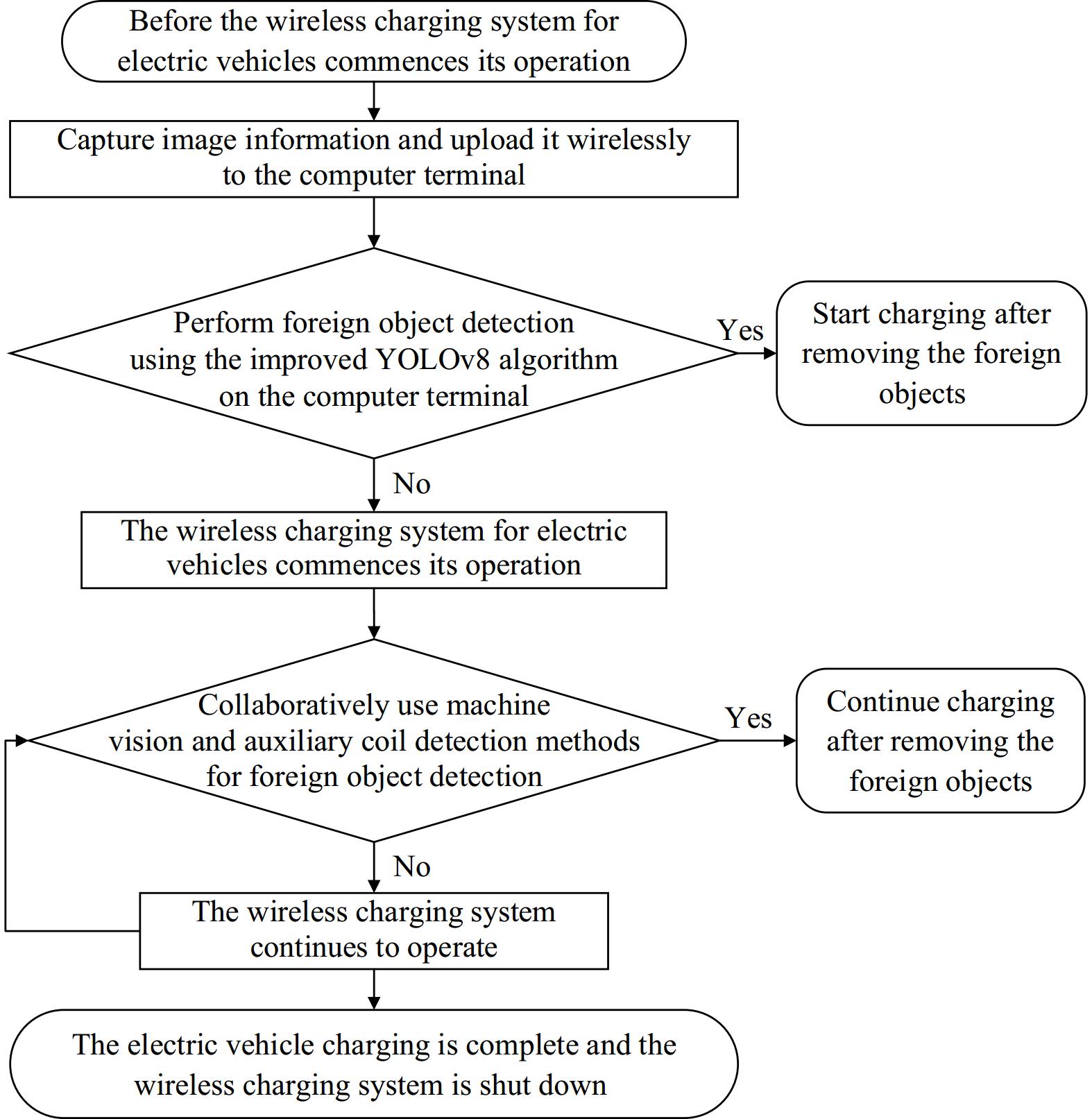
Figure 3.
Overall flowchart of metal foreign body detection implementation plan.
First, before the wireless charging system commences its operation, a machine vision detection method based on the improved YOLOv8 model is utilized, for the following reasons:
(1) In the SAE J2954_201904 standard, foreign objects should be detected at all times. Before parking, the system is in an inactive state and the auxiliary coils cannot function, which is precisely where machine vision detection methods come in handy to compensate for this limitation.
(2) Before parking for charging, the charging area is unobstructed, making it easier for metal foreign objects to fall into the charging area.
(3) Machine vision detection methods can, to a certain extent, avoid repeated start-stop of electric vehicle charging.
The reasons for using machine vision and auxiliary coil detection methods synergistically during the operation of the wireless charging system are as follows:
(1) At this point, the wireless charging system is already in operation, allowing the use of auxiliary coil detection methods for monitoring.
(2) The auxiliary coil detection method offers faster detection speeds. When the power supply to the transmitting coil is activated, a magnetic field exists in the wireless charging area. In the presence of metal foreign objects, the induced voltage in the auxiliary coil will immediately change.
(3) The detection method based on machine vision is susceptible to interference from external weather and lighting conditions, while the auxiliary coil detection has stronger resistance to external environmental interference, forming a complementary relationship with the machine vision method.
(4) When identical metal foreign objects fall onto symmetrical auxiliary coils, it is prone to cause detection blind spots in the auxiliary coils. In such cases, the machine vision detection method can serve as a supplement to the auxiliary coil detection method.
(5) The synergistic use of the two detection methods achieves more precise detection of metal foreign objects, further enhancing the safety of the wireless charging system.
-
The electric vehicle wireless charging system primarily consists of two parts: the primary transmitting end and the secondary receiving end. The foreign object detection device is installed between the two limit stops of the parking space, as shown in Fig. 4. The machine vision foreign object detection device mainly includes an image acquisition module, a wireless transmission module, and a computer terminal for processing image data. The core component of the image acquisition module is a digital camera, which is used to capture image data. The image data is transmitted to the computer terminal via the wireless transmission module chip. At the computer terminal, the improved YOLOv8 model is employed to analyze and process the image data, achieving real-time detection of foreign objects. If no foreign objects are detected, charging commences. If foreign objects are detected, the computer terminal transmits the detection result to the wireless transmission module chip, which sends a stop charging command to the transmitting coil and notifies staff to promptly remove the foreign objects before charging resumes.
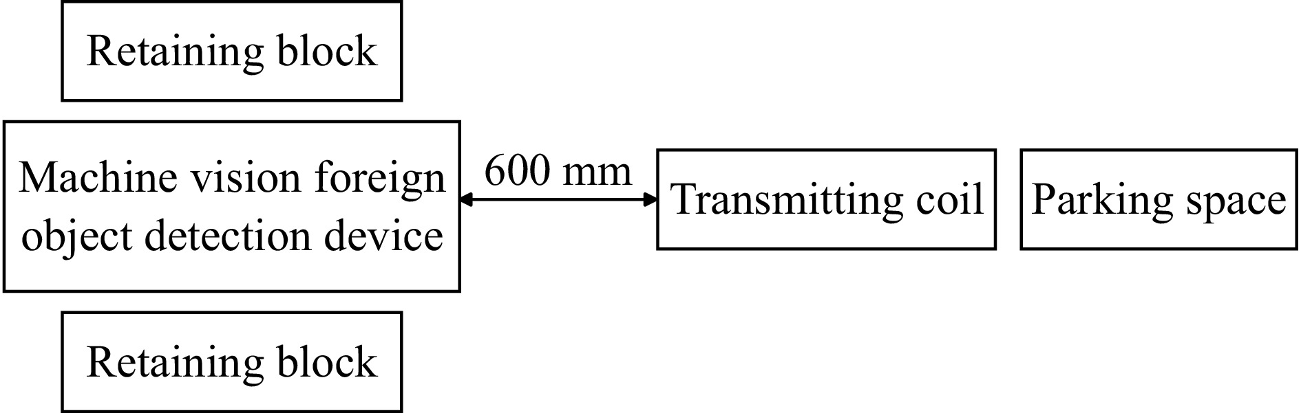
Figure 4.
Installation diagram of machine vision foreign object detection device.
The detection principle based on YOLOv8 machine vision
-
The YOLO algorithm is a classic object detection algorithm in the field of machine vision, renowned for its efficiency and real-time performance. Among the classic YOLO models, YOLOv8 stands out in the realm of image recognition. The core components of the YOLOv8 algorithm consist of the input end, backbone network, neck network, and output end. The input end initially processes the input image, primarily through operations such as mosaic data augmentation, adaptive anchor box calculation, and adaptive gray-scale padding. The backbone network extracts high-level semantic features from the input image, capturing information like the texture and shape of objects. The neck network's role is to fuse feature maps of different scales, enabling better detection of objects of varying sizes. The fused feature maps are then subjected to object detection by the output end.
The YOLOv8 model can be categorized into five variations: n, s, l, m, and x, tailored for different purposes. Among them, YOLOv8n boasts the fastest detection speed and the smallest number of detection parameters, making it ideally suited for real-time detection. Therefore, this paper adopts the YOLOv8n model as the fundamental model for machine vision. Figure 5a depicts the structure of the YOLOv8 model, where CBS performs convolutional operations, SPPF represents the Spatial Pyramid Pooling Fast module, Upsample is the upsampling module, Concat is the feature concatenation module, and Detect is the detection head.
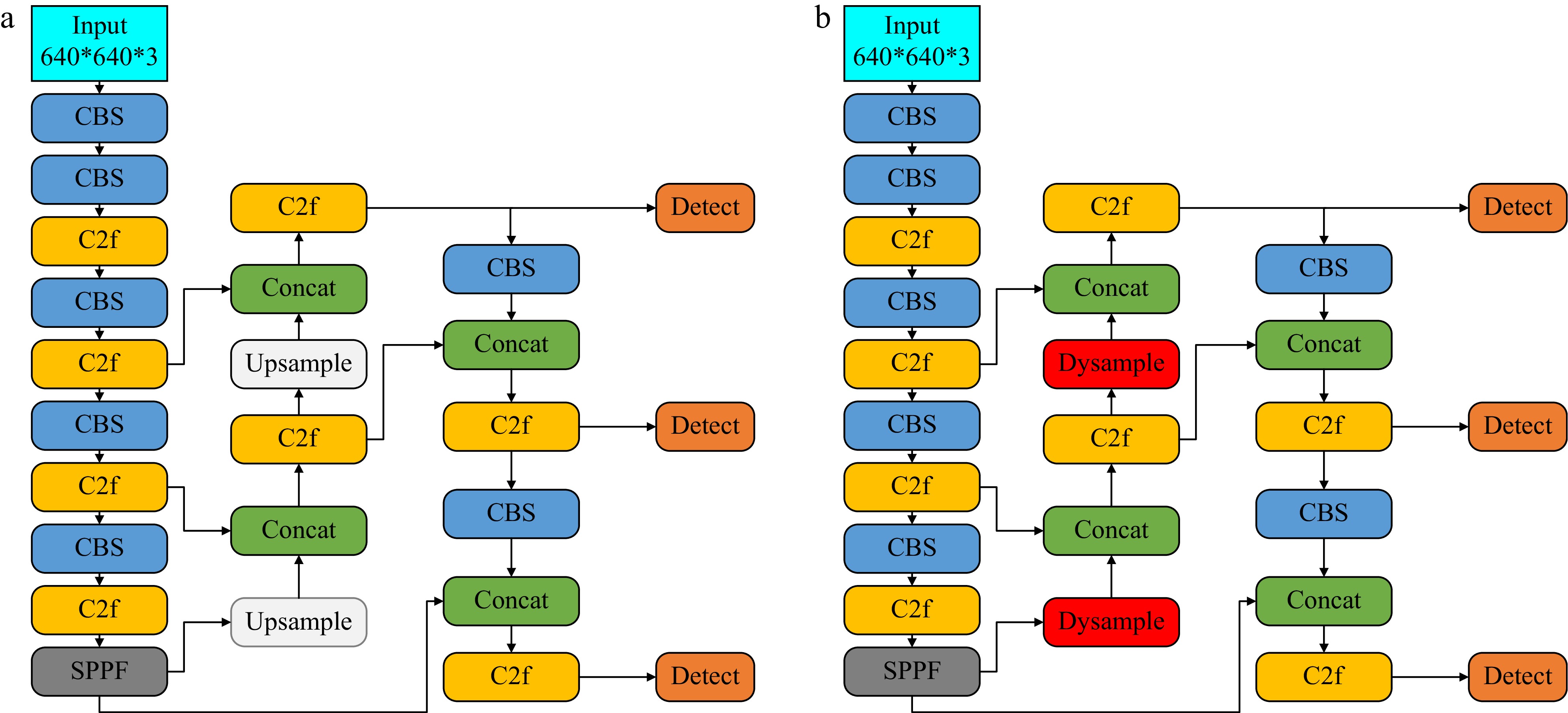
Figure 5.
Model structure diagram: (a) YOLOv8, (b) improved YOLOv8.
Improved detection principles for YOLOv8 machine vision
-
By incorporating a kernel-based dynamic upsampling module, the detection performance of the algorithm can be enhanced. However, this approach requires more computational resources, which is not in line with the requirements of real-time detection. Therefore, this paper introduces a lightweight upsampling module, Dysample, into the original YOLOv8 model to replace the existing Upsample module. Dysample focuses sampling points on the target region while Ignoring background information, enhancing the algorithm's anti-interference capability. The improved YOLOv8 model architecture is illustrated in Fig. 5b. In Fig. 5b, CBS performs convolutional operations, SPPF represents the Spatial Pyramid Pooling Fast module, Dysample is the lightweight upsampling module, Concat is the feature concatenation module, and Detect is the detection head.
Metal foreign object detection method based on center-symmetric auxiliary coil
Detection principle of center-symmetric auxiliary coil
-
The detection principle of the center-symmetric auxiliary coil is based on the principle of electromagnetic induction. When a metal foreign object enters the wireless charging system and falls above the auxiliary coil, the equivalent inductance and equivalent resistance of the center-symmetric auxiliary coil will both undergo changes, resulting in a variation in the output-induced voltage of the center-symmetric auxiliary coil. Different types and sizes of metal foreign objects have different equivalent inductances and equivalent resistances, which affect the degree of parameter changes in the center-symmetric auxiliary coil differently. The more drastic the changes in the parameters of the center-symmetric auxiliary coil, the easier it is to detect. The output power of the electric vehicle wireless charging system designed in this paper is set at 3.3 kW.
The overall circuit structure of the LCC-S type magnetically coupled wireless power transmission system is shown in Fig. 6. In Fig. 6, Uoc is the DC power source, which is converted into high-frequency AC power through a full-bridge inverter circuit. The primary side components include the compensation inductor Lp, the parallel compensation capacitor Cp, the series compensation capacitor C1, L1 and L2 are the self-inductances of the transmitting coil and the receiving coil respectively, M is the mutual inductance between coils L1 and L2, and L3 and L4 are the self-inductances of a set of symmetrical auxiliary coils. The secondary side components include the compensation capacitor C2, the filter capacitor Cin, and RL represents the load resistance.
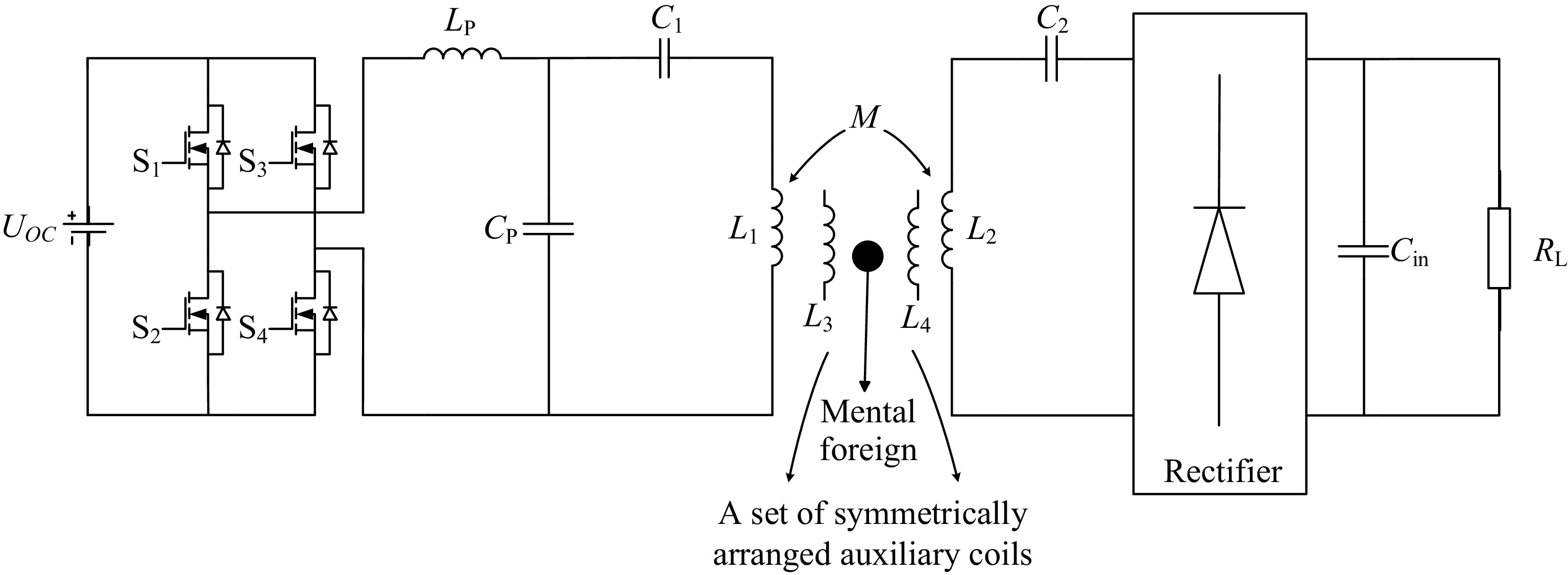
Figure 6.
Equivalent circuit of LCC-S wireless power transfer system.
Design scheme of center-symmetric auxiliary coil
-
In this paper, a novel design for an auxiliary coil structure is introduced, depicted in Fig. 7a. This design features a balanced coil configuration, with a set of auxiliary coils symmetrically positioned on either side. Due to the magnetic field symmetry of the primary transmitting coil during normal operation of the wireless charging system, the induced voltages in auxiliary coils A1 and B1 are identical, yielding a zero voltage difference between them. Detection of metal foreign objects within the system is achieved by comparing the voltage differences between these two coils. Figure 7b illustrates a scenario where the black area signifies the presence of a metal foreign object. When this object is situated precisely in the center, covering an equal area on both A1 and B1 auxiliary coils, it influences both coils equally, resulting in no voltage difference and thus a detection blind spot. Consequently, the initial design cannot detect such a centrally placed metal object. To overcome this limitation, an enhanced auxiliary coil design is proposed in Fig. 8a.
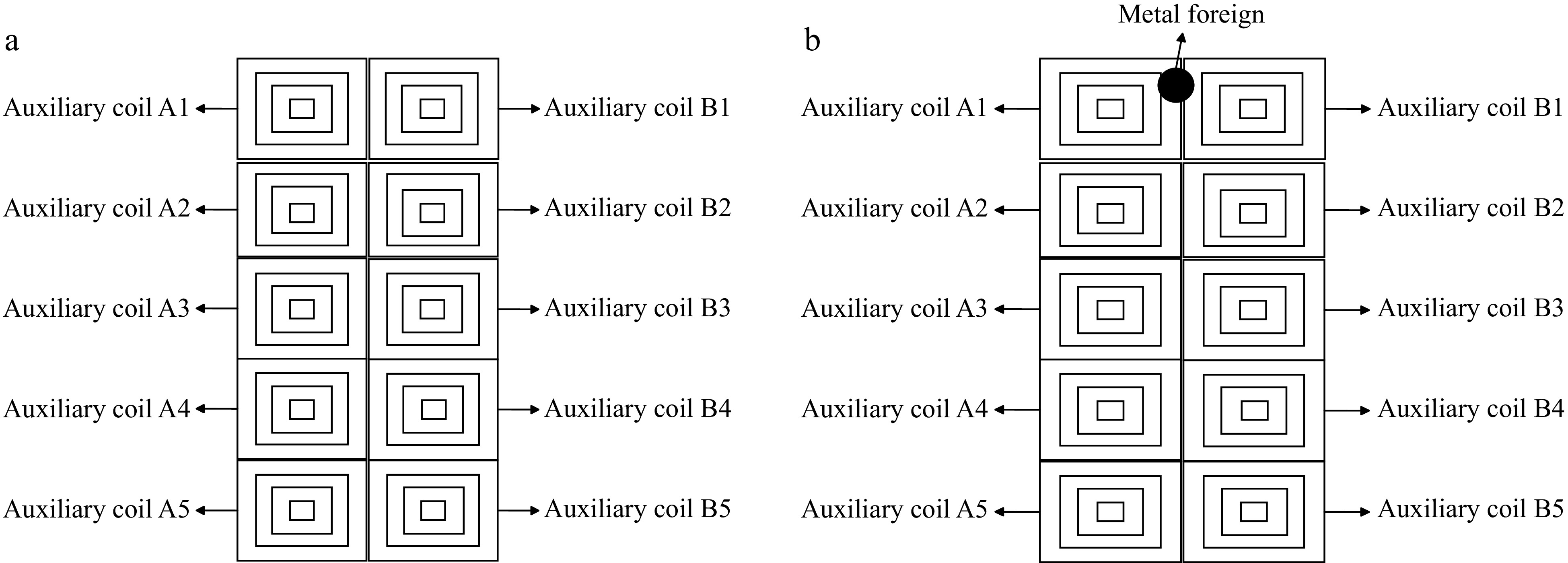
Figure 7.
Structure diagram of auxiliary coil: (a) without foreign object, (b) with foreign object.
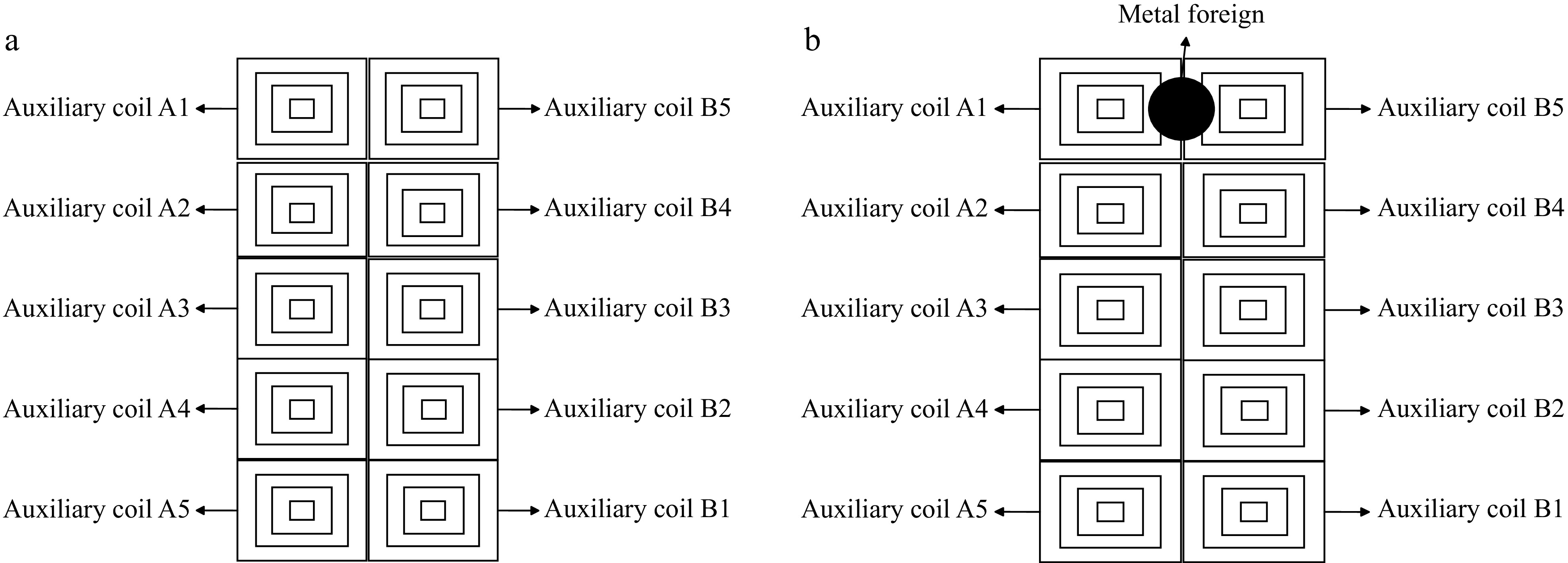
Figure 8.
Structural diagram of improved auxiliary coil: (a) without foreign object, (b) with foreign object.
The previous design's left-right symmetry has been revised to a central symmetry, placing auxiliary coil A1 in the upper left corner and auxiliary coil B1 in the lower right corner, forming a new set of auxiliary coils. In the scenario depicted in Fig. 8b, a metal foreign object is present at a location where the original detection method fails to identify it. However, with the improved auxiliary coil design, the induced voltage in auxiliary coil A1 undergoes a change while the induced voltage in auxiliary coil B1 remains unaffected. Consequently, a voltage difference arises, causing the differential circuit output to deviate from zero. This enables the system to detect the presence of the metal foreign object.
-
As shown in Fig. 9, this paper combines the use of two detection methods to achieve information interaction and feedback. Using machine vision detection before the electric vehicle wireless charging system starts operation can effectively eliminate detection blind spots and promptly transmit detection information to the central control platform. During the operation of the electric vehicle wireless charging system, the system faces the process of foreign objects appearing and disappearing. In the process of foreign objects appearing, the auxiliary coils first detect the entry of foreign objects into the wireless charging area, transmit the detection information to the central control platform, and the central control platform sends a stop charging command, alarm reminder, and stops machine vision detection. In the process of foreign objects disappearing, the auxiliary coils detect that the foreign objects have left the wireless charging area, transmit the detection information to the central control platform, and the central control platform sends a start charging command and initiates machine vision detection. At this stage, the machine vision detection method serves as a supplement to the auxiliary coil detection method. When exactly two identical metal foreign objects fall on symmetrical auxiliary coils, the machine vision detection method will have a faster detection speed to transmit the detection information to the central control platform. Therefore, in summary, at this stage, machine vision and auxiliary coils are used synergistically to improve the accuracy and speed of foreign object detection. This paper analyzes the effectiveness of the collaborative optimization detection method combining machine vision and auxiliary coils through simulation verification.
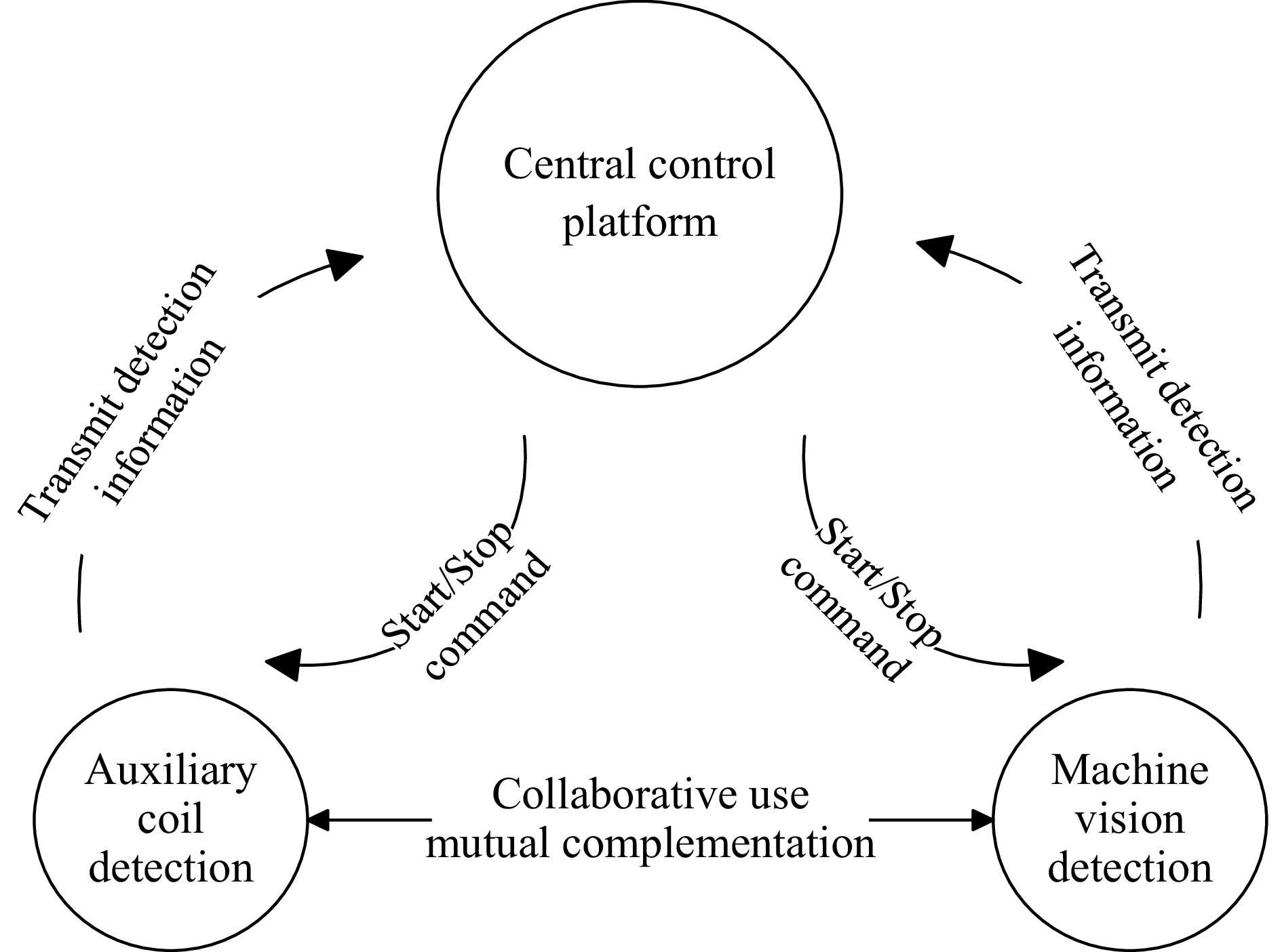
Figure 9.
Collaborative optimization-based foreign body detection method.
Based on the detection principle of the improved YOLOv8 machine vision detection method and the detection principle of the centrally symmetric auxiliary coil, this paper conducts simulation verification to analyze the effectiveness of the collaborative optimization detection method combining machine vision and auxiliary coils.
Simulation and analysis of machine vision detection method
-
The simulation in this paper was conducted on a 64-bit Windows 11 operating system, with an RTX 4060 GPU featuring 8 GB of video memory, an Intel Core R7-7840H CPU, and 16 GB of host memory. The programming language used was Python 3.9.13, CUDA version 12.2.146, and the batch size was set to 10 with 150 iterations. The training was performed based on the deep learning framework Pytorch 1.11.0. The dataset used in this paper comprises 1,500 images across four categories, including coins, drink cans, screws, and nuts as metal foreign objects. The dataset was randomly divided into a training set (1,050 images), a validation set (300 images), and a test set (150 images) in a 7:2:1 ratio. In this paper, precision is used to evaluate the model. As shown in the comparison between Fig. 10a and b, the improved YOLOv8 model achieves a 3.6% higher precision than the original YOLOv8 model, thereby verifying the effectiveness of the improved model proposed in this paper.
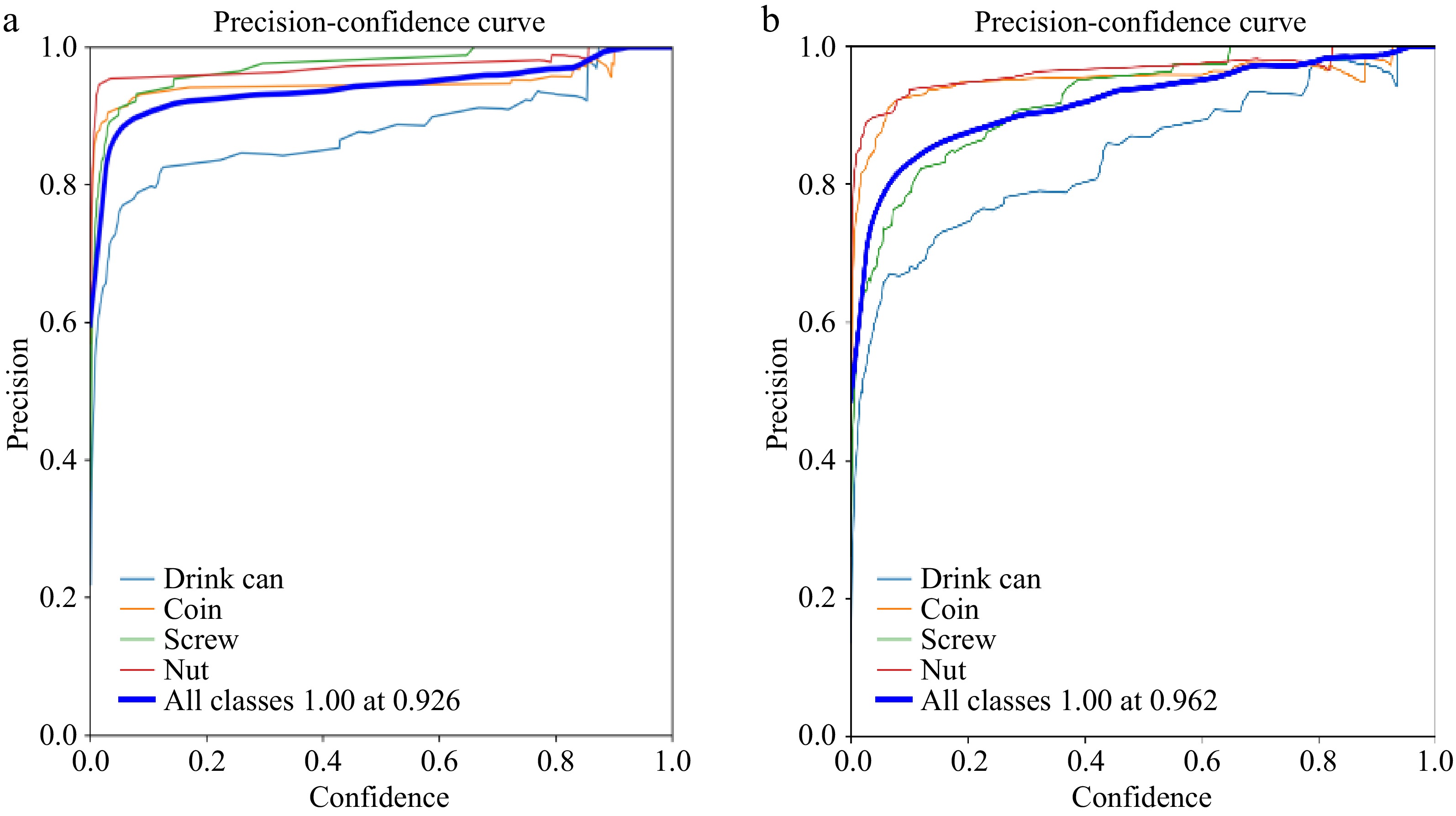
Figure 10.
Precision curve: (a) YOLOv8 model, (b) improved YOLOv8 model.
The confidence level indicates the likelihood that the detection system identifies a detected object as a foreign body, with a higher confidence level representing a greater probability of being judged as a foreign body. As can be seen from the comparison between Fig. 11a, b, and c, when detecting foreign bodies such as screws and nuts, the improved YOLOv8 algorithm exhibits an increased confidence level compared to the original YOLOv8 algorithm, thereby verifying the effectiveness of the improved algorithm proposed in this paper.
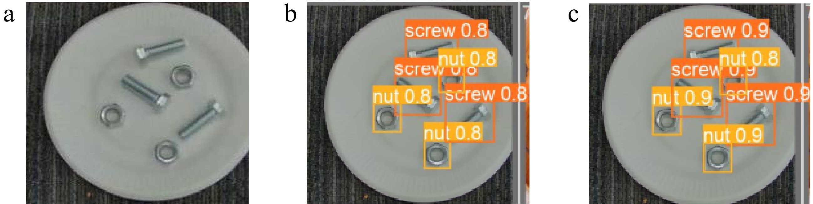
Figure 11.
Actual detection effect of screws and nuts: (a) original image, (b)YOLOv8n, (c) improved YOLOv8n.
Simulation and analysis of auxiliary coil detection method
-
To gain a deeper understanding of how metal foreign objects affect the wireless charging system of electric vehicles, this paper employs the finite element analysis tool COMSOL to create models of both the electromagnetic coupling and detection coil mechanisms within the system. The resultant data is subsequently integrated into a comprehensive circuit system that encompasses both the electric vehicle's wireless charging system and its detection circuit. This integrated system is then simulated and analyzed using Simulink, with the objective of confirming the practicality of the proposed centrally symmetric auxiliary coil. The placement diagram of the auxiliary coil is shown in Fig. 12, and Table 2 presents the system simulation circuit parameters, Table 3 presents the simulation model parameters of the electromagnetic coupling mechanism.
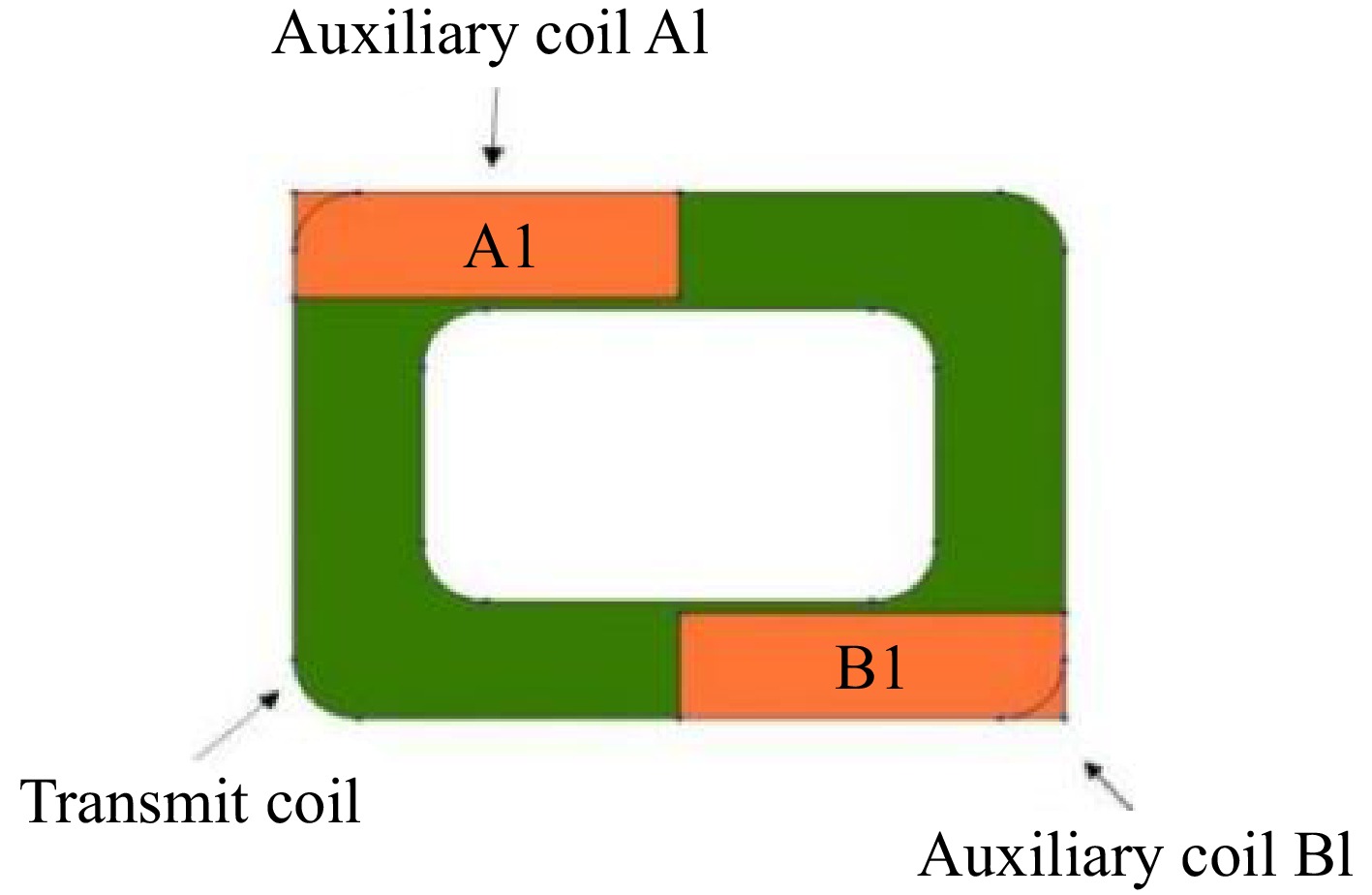
Figure 12.
Magnetic field simulation model.
Table 2. System simulation circuit parameters.
Parameters Values UOC/(V) 100 Initial value of system load RL/Ω 19 LP (μH) 7 CP (nF) 452 C1 (nF) 91 L3 (μH) 70 L1 (μH) 103.5 L2 (μH) 80 C2 (nF) 85 Cin (μF) 50 M (μH) 25 L4 (μH) 60 Table 3. Electromagnetic simulation model parameters.
Parameters Values Auxiliary coil turns 4 Auxiliary coil wire diameter 5 Auxiliary coil size (mm) 30 × 9 Primary coil size (mm) 580 × 420 Primary coil diameter (mm) 5 Number of turns of primary coil 15 Secondary coil size (mm) 320 × 320 Secondary coil wire diameter (mm) 5 Auxiliary coil turns 4 Number of turns of secondary coil 15 Simulation analysis of the influence of different metal foreign objects
-
To verify the proposed central symmetry auxiliary coil detection method, firstly, the impact of different metal foreign objects on the output voltage of the detection system was studied. The simulation results are shown in Fig. 13. When t = 0.01 s, the metal foreign object enters the coupling mechanism. Figure 13a shows that a 1-yuan coin foreign object falls on the auxiliary coil A1, and Fig. 13b shows that a 5 cm × 7.5 cm aluminum plate foreign object falls on to the auxiliary coil A1.
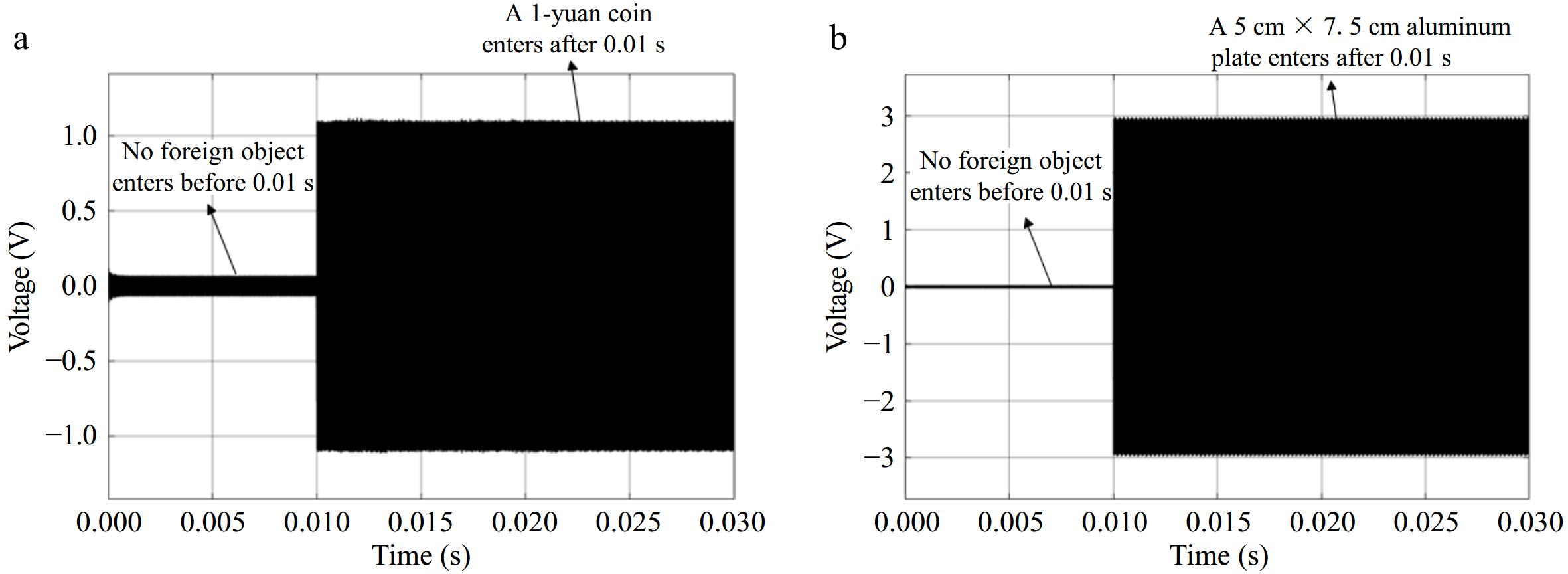
Figure 13.
Voltage fluctuation caused by foreign objects with a load of 19 Ω: (a) a 1-yuan coin, (b) a 5 cm × 7.5 cm aluminum plate.
Due to specific flaws in the circuit design, the detection system produces an output voltage of approximately 0.1 V. The threshold for the detection system to determine the presence of metal foreign objects is set at 0.1 V. As illustrated in Fig. 13a, before 0.01 s, no metal foreign object is present in the coupling mechanism. However, when a 1-yuan coin is introduced, the output voltage of the detection system rises to 1.1 V, exceeding the set threshold. Similarly, Fig. 13b demonstrates that when a 5 cm × 7.5 cm aluminum plate is placed in the coupling mechanism, the detection system's output voltage reaches 3 V, significantly above the threshold, indicating the presence of a metal foreign object. Based on the simulation outcomes of the detection system's output voltage, it is evident that the center-symmetric auxiliary coil proposed in this paper exhibits excellent detection capabilities for smaller metal objects, such as coins.
Simulation analysis of changes in system load parameters
-
To study the impact of load parameter changes in the wireless charging system on the detection effect, Fig. 14a shows the output voltage of the detection system for a 1-yuan coin foreign object when the load is 15 Ω, and Fig. 14b shows the output voltage of the detection system for a 5 cm × 7.5 cm aluminum plate foreign object when the load is 15 Ω. In Fig. 14a, the system load RL is 15 Ω. When t = 0.01 s, the metal foreign object enters the coupling mechanism, and the output voltage of the detection system at this time is 1.3 V. In Fig. 14b, the system's load RL remains at 15 Ω. At the moment when t = 0.01 s, a metal foreign object enters the coupling mechanism, causing the detection system's output voltage to rise to 3.1 V, both of which surpass the predefined threshold voltage. This indicates that the system can accurately identify the presence of metal foreign objects, even when the system load undergoes certain fluctuations. Therefore, the detection method proposed in this paper demonstrates robust anti-interference capabilities and wide applicability.
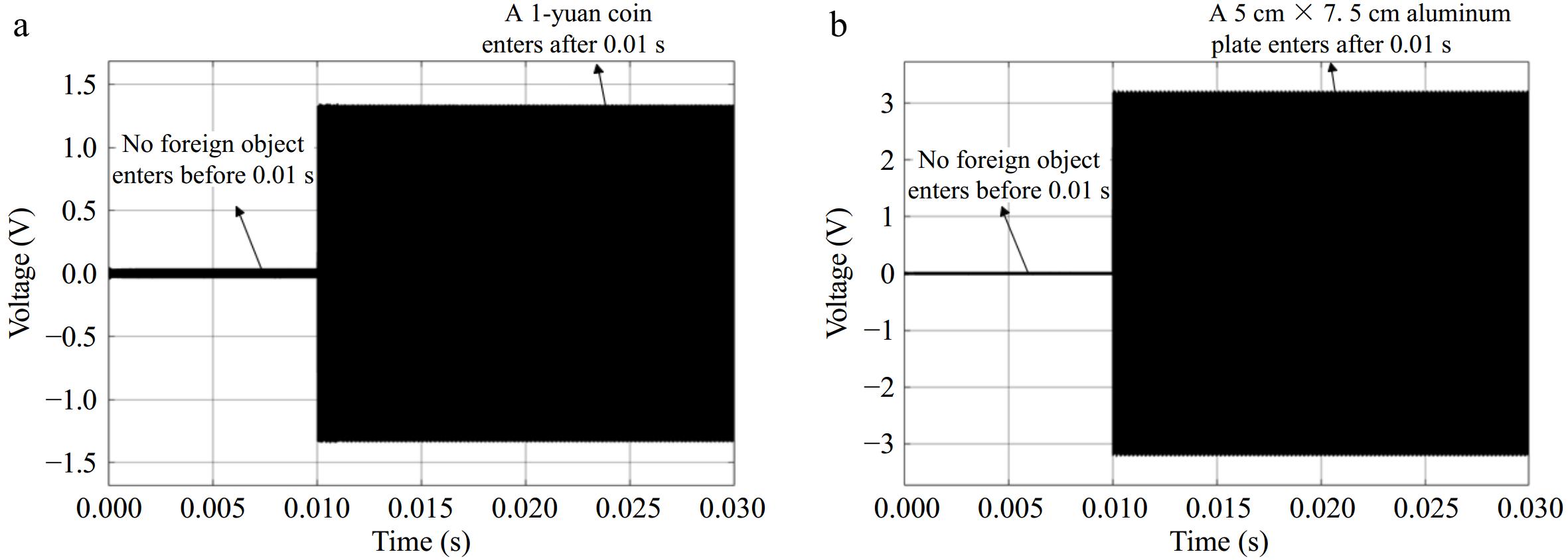
Figure 14.
Voltage fluctuation caused by foreign objects with a load of 15 Ω: (a) a 1-yuan coin, (b) a 5 cm × 7.5 cm aluminum plate.
Simulation analysis of system output voltage fluctuation
-
Fig. 15a shows the detection analysis of a 1-yuan coin. Before 0.02 s, the system input voltage is 100 V. After 0.02 s, the system input voltage drops to 80 V. At this point, the output voltage of the detection system is around 1 V, which is higher than the set threshold voltage. Therefore, the system can determine the presence of metal foreign objects. Fig. 15b presents the detection analysis of a 5 cm × 7.5 cm aluminum plate. At this time, the output voltage of the detection system is around 2.5 V, still higher than the set threshold voltage. Based on the above analysis, when the input voltage of the wireless charging system fluctuates from 100 V to 70 V, the detection method proposed in this paper can still effectively detect metal foreign objects, indicating that the method proposed in this paper has strong anti-interference ability.
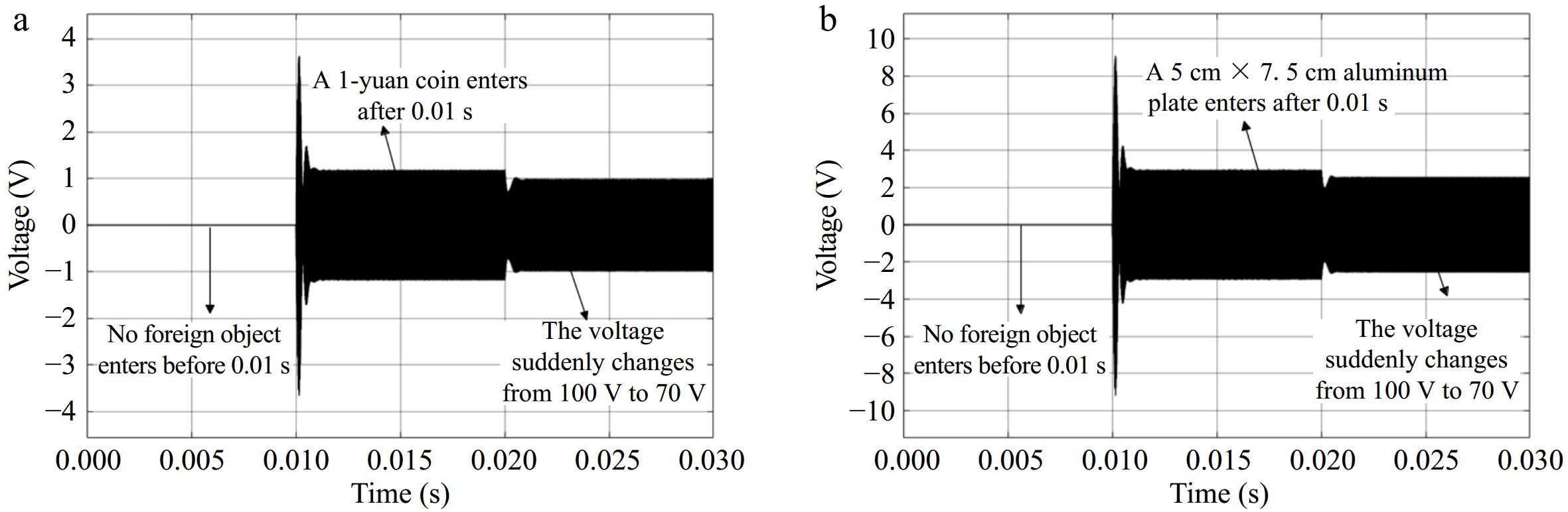
Figure 15.
Voltage fluctuation caused by system input voltage variation: (a) a 1-yuan coin, (b) a 5 cm × 7.5 cm aluminum plate.
-
This paper addresses the issue of foreign object detection in electric vehicle wireless charging systems. Utilizing COMSOL simulation software, it evaluates how metallic foreign objects affect the wireless charging process and introduces a detection method that combines machine vision with auxiliary coils. Before initiating the wireless charging, machine vision is used to spot any metallic foreign objects. During charging, the method enhances detection by integrating machine vision with auxiliary coils. During the charging process, the method combines machine vision with auxiliary coils for enhanced metal foreign object detection. Simulation results demonstrate that the improved YOLOv8 machine vision method achieves a 3.6% increase in accuracy, while the auxiliary coil detection method effectively identifies metallic foreign objects such as a 1-yuan coin and a 5 cm × 7.5 cm aluminum plate. The collaborative use of two detection methods can better ensure the safety and charging efficiency of the wireless charging system.
This work was supported in part by the 2024 Ministry of Education Humanities and Social Sciences Research Planning Fund Project (24YJAZH116).
-
The authors confirm contribution to the paper as follows: study conception and design: Zhang M; data collection: Zhang H; analysis and interpretation of results: Zhang M, Tao W; draft manuscript preparation: Zhang H, Tang G, Yang M. All authors reviewed the results and approved the final version of the manuscript.
-
All data generated or analyzed during this study are included in this published article.
-
The authors declare that they have no conflict of interest.
- Copyright: © 2025 by the author(s). Published by Maximum Academic Press, Fayetteville, GA. This article is an open access article distributed under Creative Commons Attribution License (CC BY 4.0), visit https://creativecommons.org/licenses/by/4.0/.
-
About this article
Cite this article
Zhang M, Zhang H, Tao W, Tang G, Yang M. 2025. Metal foreign detection method for an electric vehicle wireless charging system based on collaborative optimization of machine vision and auxiliary coil. Wireless Power Transfer 12: e003 doi: 10.48130/wpt-0024-0017 

Metal foreign detection method for an electric vehicle wireless charging system based on collaborative optimization of machine vision and auxiliary coil
- Received: 15 October 2024
- Revised: 28 November 2024
- Accepted: 09 December 2024
- Published online: 14 February 2025
Abstract: When metal foreign objects exist between the transmitting coil and the receiving coil of an electric vehicle, the eddy current effect or magnetic effect of the metal foreign object can affect the operational stability and transmission performance of the wireless charging system. To achieve rapid detection of metal foreign objects, this paper proposes a metal foreign object detection method for wireless charging systems based on collaborative optimization of machine vision and auxiliary coils. Firstly, an improved YOLOv8 machine vision method is used to detect foreign metal before charging the electric vehicle. Then, after the electric vehicle starts charging, machine vision and a centrally symmetric auxiliary coil method are used collaboratively to detect the metal foreign object. Simulation verification shows that the accuracy of the improved YOLOv8 model proposed in this paper is improved by 3.6% compared with the original model. The proposed auxiliary coil detection method can accurately detect foreign metal as small as a 1-yuan coin and as large as a 5 cm × 7.5 cm aluminum plate, verifying the effectiveness of the detection method proposed in this paper. This provides a detection idea for metal foreign object detection in electric vehicle wireless charging systems.
-
Key words:
- Electric vehicle /
- Wireless power transfer /
- Foreign object detection /
- Machine vision /
- Auxiliary coil