


-
Wireless Power Transfer (WPT) technology refers to the comprehensive application of electrical theory, power electronics, and control theory, which utilizes magnetic fields, electric fields, microwaves, or lasers to transmit energy from the power grid or battery to electrical equipment in a non-electrical manner, and solves the problem of unsafe and inflexible energy contacts[1−4]. In the past few years, the theory and technology of Magnetic Coupled Wireless Power Transfer (MC-WPT) have been widely studied and applied[5,6]. However, the MC-WPT system cannot transmit energy through metal objects due to electromagnetic shielding, and will result in severe power loss[7]. Electrical Coupled Wireless Power Transfer (EC-WPT) technology utilizes an electric field as the energy transmission medium. It can transfer energy across metals regardless of metal interference, and the electric field of the EC-WPT system is mainly concentrated between the coupling plates, greatly reducing electromagnetic interference. In addition, an EC-WPT system has unique advantages having a lightweight coupling structure, low eddy current loss, and cost[8,9], so it has increasingly attracted high attention from experts and scholars. At present, EC-WPT systems have achieved some research achievements in LED lights, biomedical equipment, mobile robots, and EV charging.
Nowadays, an increasing number of energy interactions and sharing scenarios exist showing a demand for Bidirectional Wireless Power Transfer (BWPT) technology, such as Vehicle to Grid (V2G) and portable device bidirectional charging applications[10−13]. While the research of EC-WPT technology is limited to unidirectional power transmission, the unique advantages of the bidirectional EC-WPT technology which is a type of BWPT technology make it a potential development trend[14]. The block diagram of a typical bidirectional EC-WPT system is shown in Fig. 1. Usually, the power magnitude and direction of a bidirectional EC-WPT system are controlled by the relative phase angle or magnitude of the voltages generated by the primary and secondary converters[3].
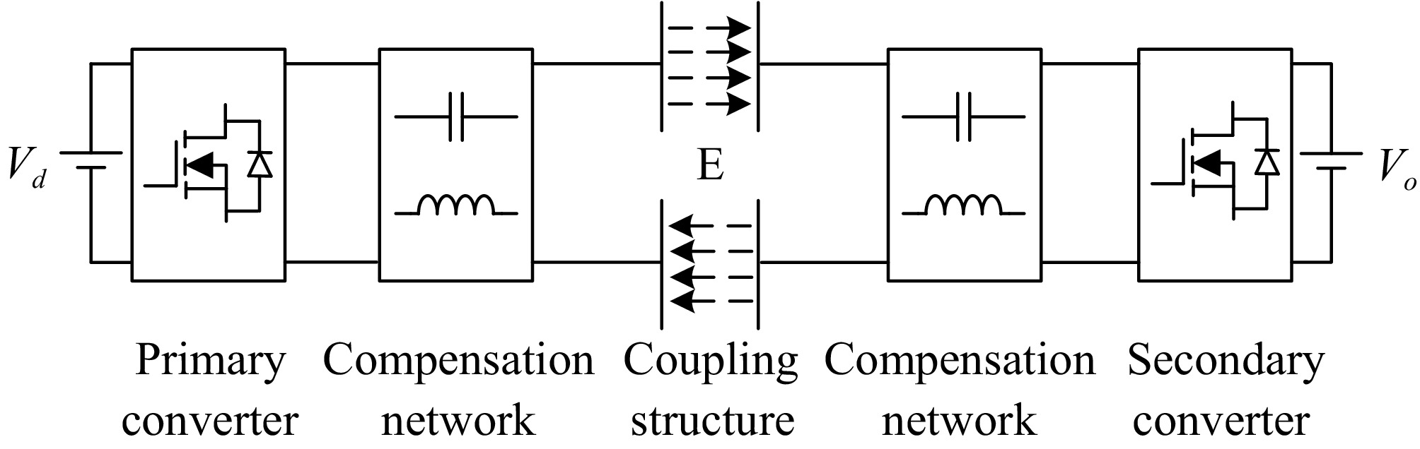
Figure 1.
Block diagram of a typical bidirectional EC-WPT system.
In practical application, the coupling plates will inevitably shift or change in transmission distance, which leads to variation in coupling capacitances (usually at the pF level), deviation in resonant frequency, and reduction in the power transmission performance. At present, some methods have been proposed and implemented, mainly including compensation network tuning control, compensation topology transformation, and power control strategies. A dynamic tuning method of the capacitance matrix is proposed to address time-varying coupling capacitors[15]. Similarly, a matrix charging platform and dynamically adjustable inductor are proposed to maintain a constant output voltage by matching different coupling capacitors[9]. However, using controllable inductors and capacitance matrices will increase the volume. Besides, a hybrid parallel connected LCL and CL topology of the BWPT system is proposed to achieve constant and effective charging of EVs in coupling misalignment[16]. An LC-CLC compensation network proposes that output power changes by less than 10% when the coupling structure shifts within a certain range[17]. However, adopting these topologies is inherently complex, with a small range of misalignment adaptation, and is susceptible to power fluctuations without active control. In addition, a control strategy of power interference observation for the BWPT system proposes regulating the relative phase angle by changing the power direction[18], which can improve the effects of coupling detuning, but the power will fluctuate continuously under the interference of phase shift angle, affecting the stability of the system. A comparative analysis including simulation and experiments between the proposed method and conventional methods to solve the misalignment of the coupling plates is shown in Table 1.
Table 1. Comparison of critical characteristics of the proposed method and conventional methods.
Ref. Method Design complexity Adjustable precision Misalignment tolerability Power disturbance [15] Capacitance matrix platform Medium Low Medium No [9] Dynamic adjustable inductor Medium Low Low No [16] hybrid parallel connected topology High Medium Low No [17] LC-CLC compensation network Medium Low Low Yes [18] Power-phase angle perturbation Medium Medium High Yes This work Autonomously track zero-crossing point of the current low High High No Therefore, in order to cope with the coupling detuning of the bidirectional EC-WPT system caused by the inevitable misalignment of the coupling plates without adding additional circuit components, complex compensation topology design, and unstable control strategy. This paper proposes an inherent frequency dynamic tracking strategy to ensure that the system operates at the resonant state before bidirectional power flow regulation to achieve the preset phase-shifting power flow regulation.
-
For the convenience of achieving energy interaction and sharing among electrical equipment, the circuit topology of the bidirectional EC-WPT system based on a dual LC compensation network is shown in Fig. 2. The primary and secondary circuits use identical full-bridge converters and bilateral LC compensation networks to promote bidirectional power flow between electrical devices. Where L1 and L2 are self-inductances of the compensation coils, C1 and C2 are compensation capacitors. vp and vr are the resonant voltages generated by the primary and secondary converters, i1 and i2 are the resonant currents, Ed and Eo are the DC voltages, Cd and Co are the DC filtering capacitors. The coupling plates P1 and P2 are placed on the primary side, while P3 and P4 are placed on the secondary side. Under the interaction of the electric field, energy is wirelessly transmitted between the coupling plates.
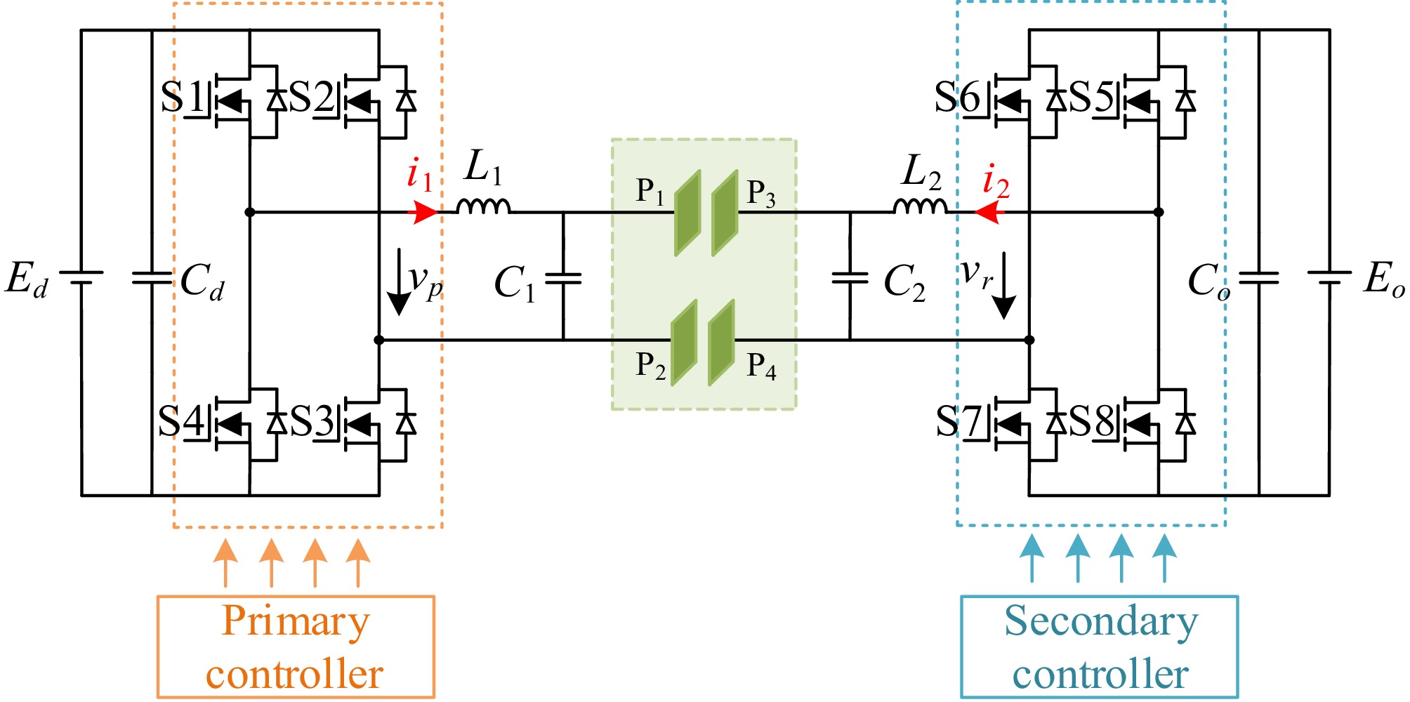
Figure 2.
Circuit topology diagram of the dual LC compensation network bidirectional EC-WPT system.
The four plates coupling structure in Fig. 2 consists of six coupling capacitances C12, C13, C14, C23, C24, and C34, which can converse to the equivalent current source model as shown in Fig. 3.
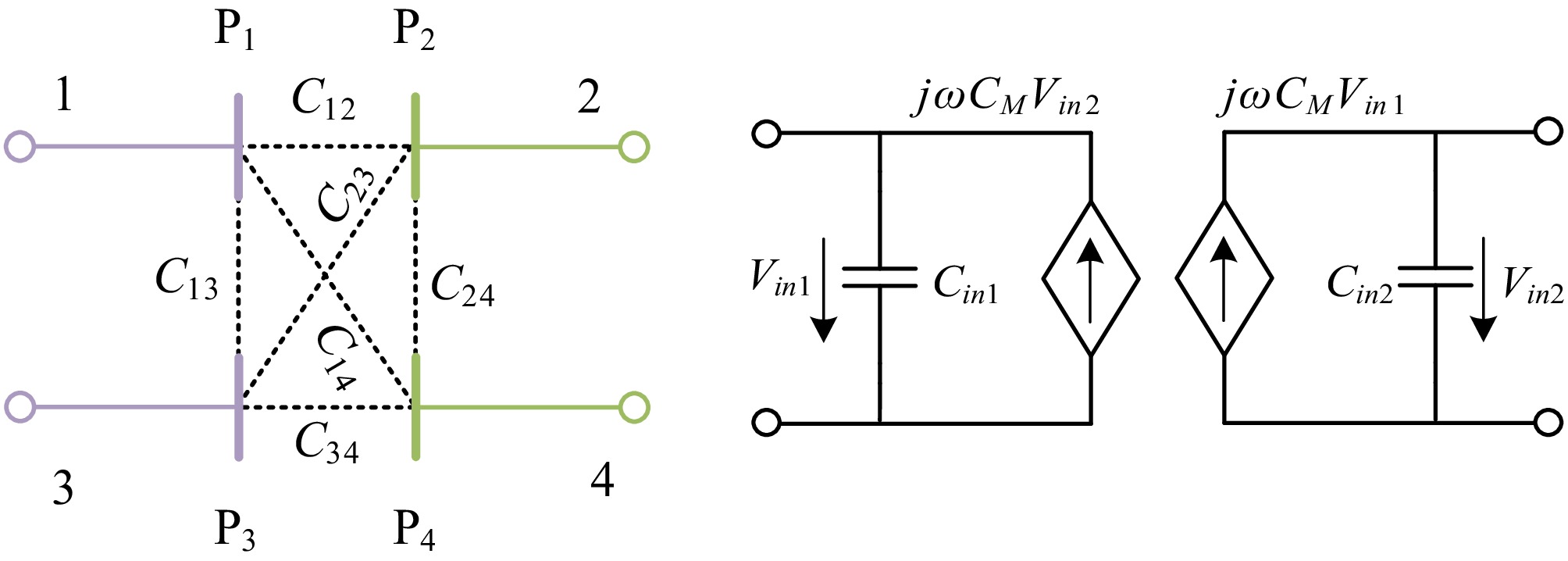
Figure 3.
Equivalent current source model of the coupling structure.
The equivalent current source related to the voltage of the coupling capacitance represents the coupling between the primary and secondary metal plates. Therefore, the equivalent self-capacitances and coupling coefficient can be expressed as:
$ \left\{ \begin{gathered} {C_{in1}} = {C_{\text{1}}} + {C_{x1}} \\ {C_{in2}}{\text{ = }}{C_2} + {C_{x2}} \\ {k_c} = {{{C_M}} \mathord{\left/ {\vphantom {{{C_M}} {\sqrt {{C_{in1}} \cdot {C_{in2}}} }}} \right. } {\sqrt {{C_{in1}} \cdot {C_{in2}}} }} \\ \end{gathered} \right. $ (1) where,
$ \left\{ \begin{gathered} {C_{x1}} = {C_{13}} + \frac{{\left( {{C_{12}} + {C_{14}}} \right)\left( {{C_{23}} + {C_{34}}} \right)}}{{{C_{12}} + {C_{14}} + {C_{23}} + {C_{34}}}} \\ {C_{x2}} = {C_{24}} + \frac{{\left( {{C_{12}} + {C_{23}}} \right)\left( {{C_{14}} + {C_{34}}} \right)}}{{{C_{12}} + {C_{14}} + {C_{23}} + {C_{34}}}} \\ {C_M} = \frac{{{C_{12}}{C_{34}} - {C_{14}}{C_{23}}}}{{{C_{12}} + {C_{14}} + {C_{23}} + {C_{34}}}} \\ \end{gathered} \right. $ (2) Thus, the two-port equivalent current source circuit model of the bidirectional EC-WPT system is shown in Fig. 4.
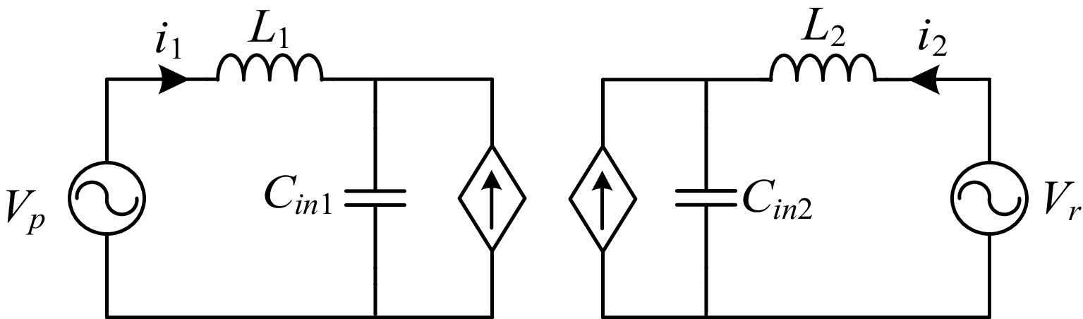
Figure 4.
Equivalent current source circuit model of the bidirectional EC-WPT system.
The high-frequency full bridge converters of the primary and secondary sides for the bidirectional EC-WPT system are driven by two synchronous controllers. Both primary and secondary controllers use phase shifting technology, the primary controller generates an internal phase shift angle φ1 to the primary converter and the secondary controller generates an internal phase shift angle φ2 for the secondary converter to adjust the output voltage of the primary and secondary side converters accordingly. Additionally, δ and β are the adjustable delay phase angle between the secondary and the primary control signal. θ is the relative phase angle between the output voltage generated by the primary and secondary converters. The switching sequences and resonant voltages of the primary and secondary converters are shown in Fig. 5.
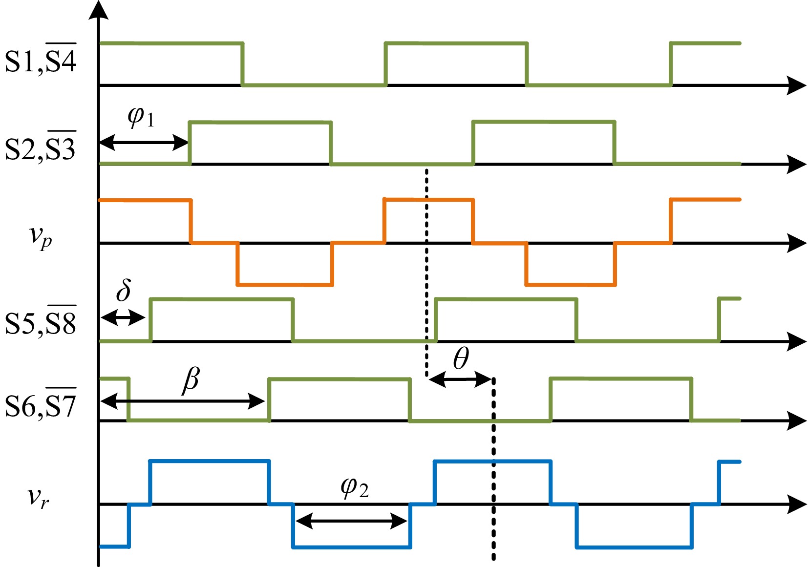
Figure 5.
Switching sequences and resonant voltages of the primary and receiver converters.
Usually, φ1
$ \in $ $ \in $ $ \in $ $ \in $ Table 2. The relationship of the phase-shift angles.
β-δ θ $\varphi $2 β < δ (−2π, −π] δ + ($\varphi $2−$\varphi $1)/2 β − δ + 2π (−π, 0) δ − ($\varphi $2 + $\varphi $1)/2 + π −(β − δ) β > δ (0, π] δ + ($\varphi $2 − $\varphi $1)/2 β − δ (π, 2π) δ − ($\varphi $2 + $\varphi $1)/2 + π − (β − δ) + 2π $ {\text θ} = \left\{ \begin{gathered} \delta + \dfrac{{{\varphi _2}}}{2} - \dfrac{{{\varphi _1}}}{2},\begin{array}{*{20}{c}} {}&{} \end{array}{\text{2}}k{\text π} \lt \beta - \delta \leqslant \left( {{\text{2}}k + 1} \right){\text π} \\ \delta - \dfrac{{{\varphi _2}}}{2} - \dfrac{{{\varphi _1}}}{2} + {\text π} ,\begin{array}{*{20}{c}} {} \end{array}\left( {{\text{2}}k + 1} \right){\text π} \lt \beta - \delta \lt \left( {{\text{2}}k + 2} \right){\text π} \\ \end{gathered} \right.\begin{array}{*{20}{c}} {} \end{array}\left( {k = 0, \pm 1, \pm 2} \right) $ (3) Therefore, it can be seen from Eqn (3) that the relative phase angle θ can be controlled by any combination of
$\varphi $ $\varphi $ The primary and secondary converter switches (S1−S4, S5−S8) are operated at a duty cycle of 50% and driving frequency fs to generate resonant voltages vp and vr. Therefore, the output fundamental voltage of the full-bridge converters can be obtained as:
$ \left\{ \begin{array}{l} {v_p} = \dfrac{{4{E_d}}}{{\text π}}\cos \left( {{\omega _s}t} \right)\sin \left( {\dfrac{{{\varphi _1}}}{2}} \right) \\ {v_r} = \dfrac{{4{E_o}}}{{\text π}}\cos \left( {{\omega _s}t - \theta } \right)\sin \left( {\dfrac{{{\varphi _2}}}{2}} \right) \\ \end{array} \right. $ (4) where, ωs = 2πfs.
According to the KVL equation, the relationship between the currents and voltages of system circuit components can be derived as follows:
$ \left\{ \begin{gathered} {V_p} = j\omega {L_1}{i_1} + {V_{in1}} \\ {i_1} = j\omega {C_{in1}}{V_{in1}} + j\omega {C_M}{V_{in2}} \\ {i_2} = j\omega {C_{in2}}{V_{in2}} + j\omega {C_M}{V_{in1}} \\ {V_r} = j\omega {L_2}{i_2} + {V_{in2}} \\ \end{gathered} \right. 5 $ (5) If the frequency of the bilateral LC resonant network in the bidirectional EC-WPT system is ωc, then the resonance relationship of the circuit can be obtained as follows:
$ \left\{ \begin{gathered} \omega _c^2{L_1}\dfrac{{{C_{in1}}{C_{in2}} - C_M^2}}{{{C_{in2}}}} = 1 \\ \omega _c^2{L_2}\dfrac{{{C_{in1}}{C_{in2}} - C_M^2}}{{{C_{in1}}}} = 1 \\ \end{gathered} \right. $ (6) So, the expression for the resonant currents of the primary and secondary sides can be given as:
$ \left\{ \begin{gathered} {I_1} = - j{\omega _c}\dfrac{{{C_{in1}}{C_{in2}}}}{{{C_M}}}{V_r} \\ {I_{\text{2}}} = - j{\omega _c}\dfrac{{{C_{in1}}{C_{in2}}}}{{{C_M}}}{V_p} \\ \end{gathered} \right. $ (7) Therefore, under the condition of the resonance relationship in Eqn (6), it can be obtained from Eqn (7) that the primary resonant current I1 has a phase difference of 90° with the secondary resonant voltage Vr, and is independent of the primary resonant voltage Vp. The secondary resonant current I2 has a phase difference of 90° with the primary resonant voltage Vp, and is independent of the secondary resonant voltage Vr. The power expression of the primary and secondary sides is obtained as:
$ \left\{ \begin{gathered} {P_p} = {Re} \left\{ {{V_p}I_1^ * } \right\} = \dfrac{{{\omega _c}{C_{in1}}{C_{in2}}}}{{{C_M}}}{V_p}{V_r}\sin \theta \\ {P_r} = {Re} \left\{ {{V_r}I_2^ * } \right\} = - \dfrac{{{\omega _c}{C_{in1}}{C_{in2}}}}{{{C_M}}}{V_p}{V_r}\sin \theta \\ \end{gathered} \right. $ (8) Based on the above analysis, due to φ1, φ2
$ \in $ $ \in $ $ \in $ 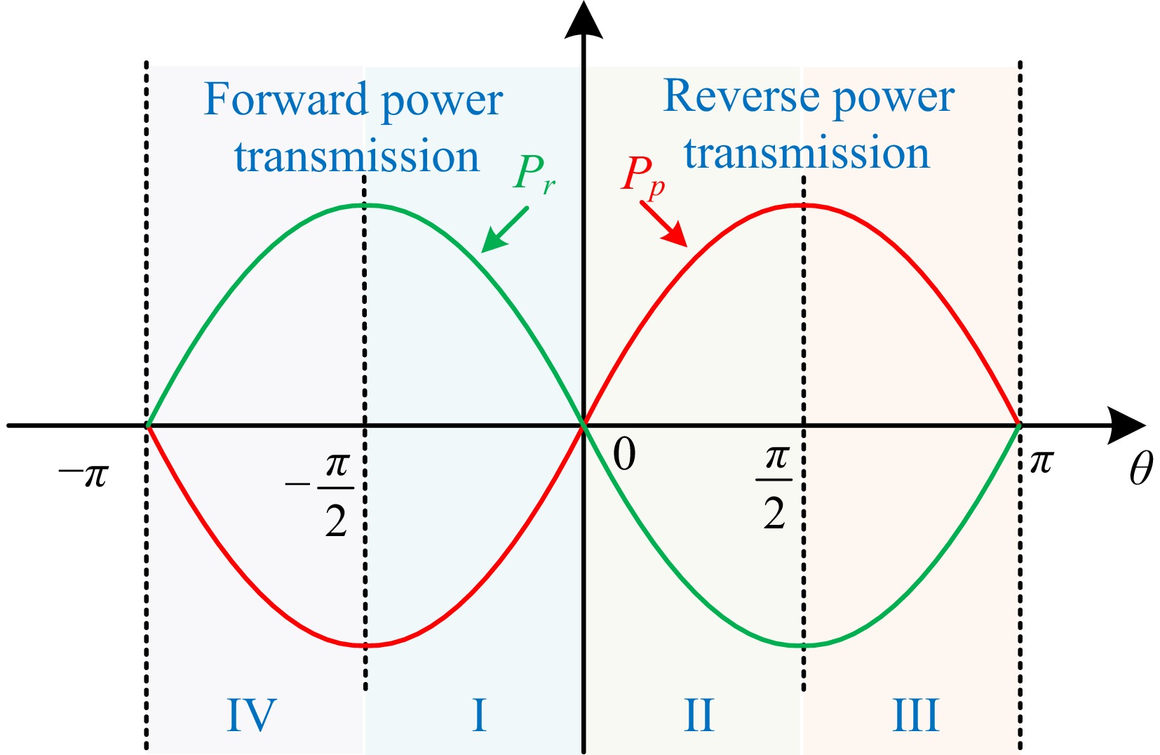
Figure 6.
Phase relationship between transmission power and relative phase angle.
However, in practice, due to the inevitable misalignment of the coupling plates, the system may not achieve perfect resonance, which will lead to changes in the power transmission. In this case, Eqn (8) is also not satisfied, so, it is very important to achieve inherent resonance frequency tracking for the bidirectional system.
-
According to KVL's law, the equivalent circuit differential equation of the bidirectional EC-WPT system shown in Fig. 4 can be expressed as:
$ \left\{ \begin{gathered} {{\dot i}_1} = - \dfrac{1}{{{L_1}}}{u_{in1}} + \dfrac{1}{{{L_1}}}{u_p} \\ {{\dot u}_{in1}} = \dfrac{{{C_{in2}}}}{\Delta }{i_1} + \dfrac{{{C_M}}}{\Delta }{i_2} \\ {{\dot u}_{in2}} = \dfrac{{{C_M}}}{\Delta }{i_1} + \dfrac{{{C_{in1}}}}{\Delta }{i_2} \\ {{\dot i}_2} = - \dfrac{1}{{{L_2}}}{u_{in2}} + \dfrac{1}{{{L_2}}}{u_r} \\ \end{gathered} \right. $ (9) where,
$ \Delta = {C_{in1}}{C_{in2}} - C_M^2 $ (10) x = [i1 uin1 uin2 i2] is the state vector of the system, u = [u1 u2]T = [up ur]T is the input vector. So, the state space model can be expressed as:
$ \dot x = Ax + Bu $ (11) where, A is the system coefficient matrix, B is the system input matrix, and can be derived as:
$ A = \left[ {\begin{array}{*{20}{c}} 0&{ - \dfrac{1}{{{L_1}}}}&0&0 \\ {\dfrac{{{C_{in2}}}}{\Delta }}&0&0&{\dfrac{{{C_M}}}{\Delta }} \\ {\dfrac{{{C_M}}}{\Delta }}&0&0&{\dfrac{{{C_{in1}}}}{\Delta }} \\ 0&0&{ - \dfrac{1}{{{L_2}}}}&0 \end{array}} \right] 12 $ (12) $ B = {\left[ {\begin{array}{*{20}{c}} {\dfrac{1}{{{L_1}}}}&0&0&0 \\ 0&0&0&{\dfrac{1}{{{L_2}}}} \end{array}} \right]^T} 13 $ (13) Considering the resonant currents i1 and i2 of primary and secondary as outputs, the output equation can be expressed as:
$ y = Cx $ (14) where,
$ \begin{gathered} y = {\left[ {\begin{array}{*{20}{c}} {{y_1}}&{{y_2}} \end{array}} \right]^T} = {\left[ {\begin{array}{*{20}{c}} {{i_1}}&{{i_2}} \end{array}} \right]^T} \\ C = \left[ {\begin{array}{*{20}{c}} 1&0&0&0 \\ 0&0&0&1 \end{array}} \right] \\ \end{gathered} 15 $ (15) The transfer function matrix of G can be expressed as:
$ G\left( s \right) = \dfrac{{Y\left( s \right)}}{{U\left( s \right)}} = C{\left( {sI - A} \right)^{ - 1}}B = \left[ {\begin{array}{*{20}{c}} {{G_{11}}\left( s \right)}&{{G_{12}}\left( s \right)} \\ {{G_{21}}\left( s \right)}&{{G_{22}}\left( s \right)} \end{array}} \right] $ (16) where,
$ \begin{gathered} {G_{11}}\left( s \right) = \dfrac{{{I_1}\left( s \right)}}{{{U_p}\left( s \right)}},\;{G_{12}}\left( s \right) = \dfrac{{{I_1}\left( s \right)}}{{{U_r}\left( s \right)}} \\ {G_{21}}\left( s \right) = \dfrac{{{I_2}\left( s \right)}}{{{U_p}\left( s \right)}},\;{G_{22}}\left( s \right) = \dfrac{{{I_2}\left( s \right)}}{{{U_r}\left( s \right)}} \\ \end{gathered} $ (17) Due to the fact that the frequency corresponding to the maximum gain of the transmission matrix in Eqn (17) is usually the resonant frequency point in the self-excited oscillation mode of the system[19], the system can automatically follow the zero-crossing point of the system resonant current to drive the converters through the self-excited oscillation mode, thereby operating at a stable inherent resonant frequency.
For simplification, a structure, in which the coupling plates are parallel, and the specific dimensions are shown in Fig. 7, where the length of the coupling plates is 300 mm, the thickness is 2 mm, the transmission distance is 10 mm, and the distance between P1−P2 and P3−P4 is 150 mm. The parameters of the coupling capacitances are given in Table 3 using the finite element simulation software of Maxwell.
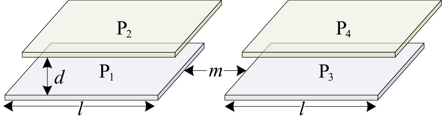
Figure 7.
Structure and dimension of coupling plates.
Table 3. The parameters of coupling capacitances.
Parameter Value Parameter Value C12 (pF) 91.3 C34 (pF) 90.56 C13 (pF) 1.62 C24 (pF) 1.62 C14 (pF) 1.38 C23 (pF) 1.38 Cx1 (pF) 47.77 Cx2 (pF) 47.77 CM (pF) 44.77 According to the circuit parameters in Table 4, the magnitude-frequency and phase-frequency curves of the system transfer function matrix is as shown in Fig. 8. It can be seen that the maximum gain is about 0.8, and the resonant frequency corresponds to 0.948 MHz.
Table 4. Circuit parameters of the system.
Parameter Value Ed (V) 100 Eo (V) 100 L1 (μH) 75 L2 (μH) 75 C1 (pF) 284 C2 (pF) 284 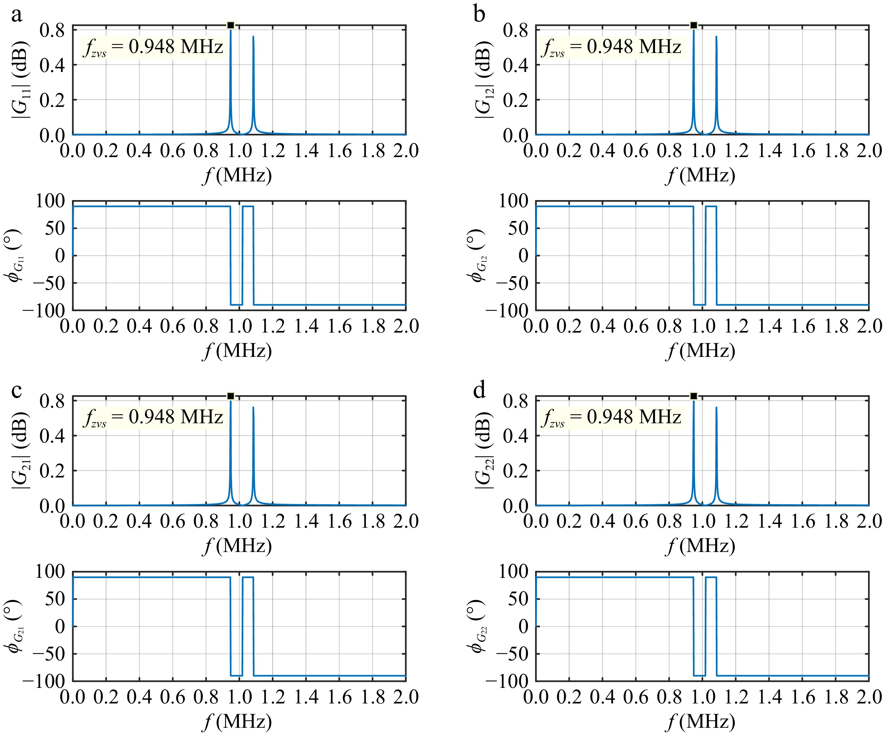
Figure 8.
The magnitude-frequency and phase-frequency curves of the system transfer function matrix.
-
According to the above analysis, the inevitable misalignment of the coupling plates can cause the system to be in a non-resonant state before the bidirectional power flow regulation. The proposed control method can track the resonant frequency automatically and stabilize operation. The simplified control diagram for frequency dynamic tracking of the bidirectional EC-WPT system is shown in Fig. 9, where the current detection circuit consists of a current collected with a current transformer, differential amplification with an operational amplifier, and zero-crossing comparation with a high-speed voltage comparator.
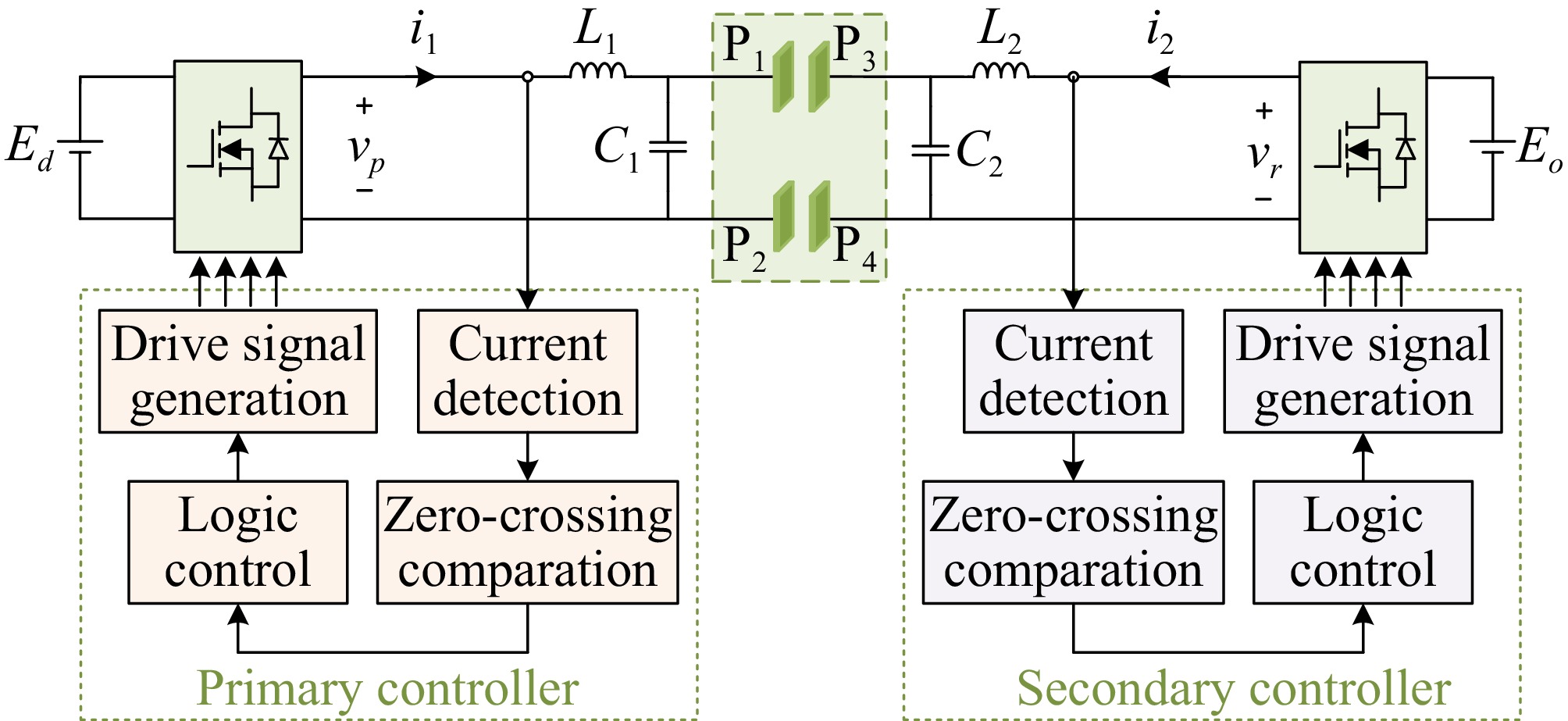
Figure 9.
The proposed frequency tracking control schematic diagram of the bidirectional EC-WPT system.
The specific procedures are as follows: During the system start-up stage, the primary and secondary controllers detect the zero-crossing of the resonant currents, where the switches S1-S4 are in phase with the output voltage signal of the primary side, and the switches S5-S8 are in inverse phase with the output voltage signal of the secondary side, which can ensure that the system is forward power transmission and vice versa.
The proposed inherent resonance frequency dynamic tracking method is shown in Fig. 10. It is worth mentioning that even if the system dynamically changes, the system uninterruptedly tracks the zero-crossing points of the resonant currents and drives the converters of the primary and secondary sides to achieve dynamic tracking of the resonant frequency.
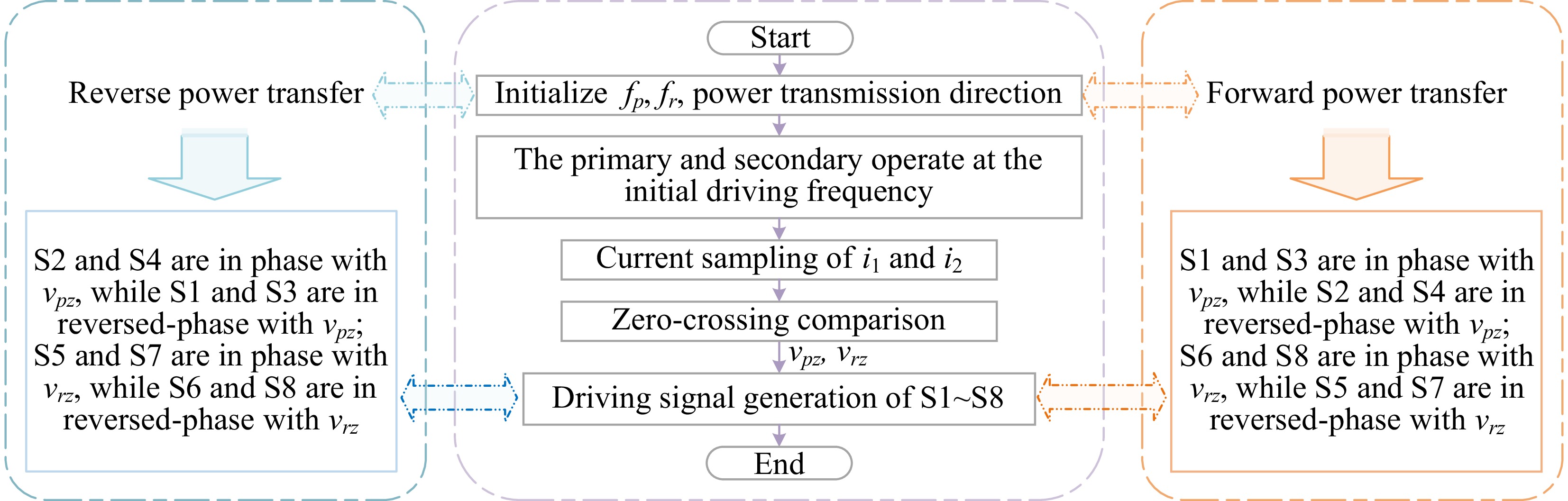
Figure 10.
Procedures of the proposed frequency tracking control schematic.
-
To verify the effectiveness of the proposed inherent resonant frequency tracking method, a bilateral LC-compensated bidirectional EC-WPT system is constructed by SIMULINK, and the waveforms of the resonant voltages and currents on the primary and secondary sides are shown in Fig. 11. Among them, Fig. 11a is the transient response view of voltages and currents, and Fig. 11b is the waveform diagram of the system driving the converters of primary and secondary sides at 1 MHz operating frequency, at which the output currents of converters oscillates periodically, mainly because the system is driving the primary and secondary converters at a constant frequency, and the phase of bilateral resonant voltages is not synchronous, causing periodic changes in the relative phase difference and continuous power oscillation. Through the inherent resonant frequency tracking method, the system operates stably at the resonant frequency by tracking the zero-crossing point of the resonant currents and it can be seen from Fig. 11c that the resonant currents of the primary and the secondary sides remain stable by the proposed method, not only is the phase synchronized, but also the inherent resonant frequency of the bidirectional system can be autonomously tracked.
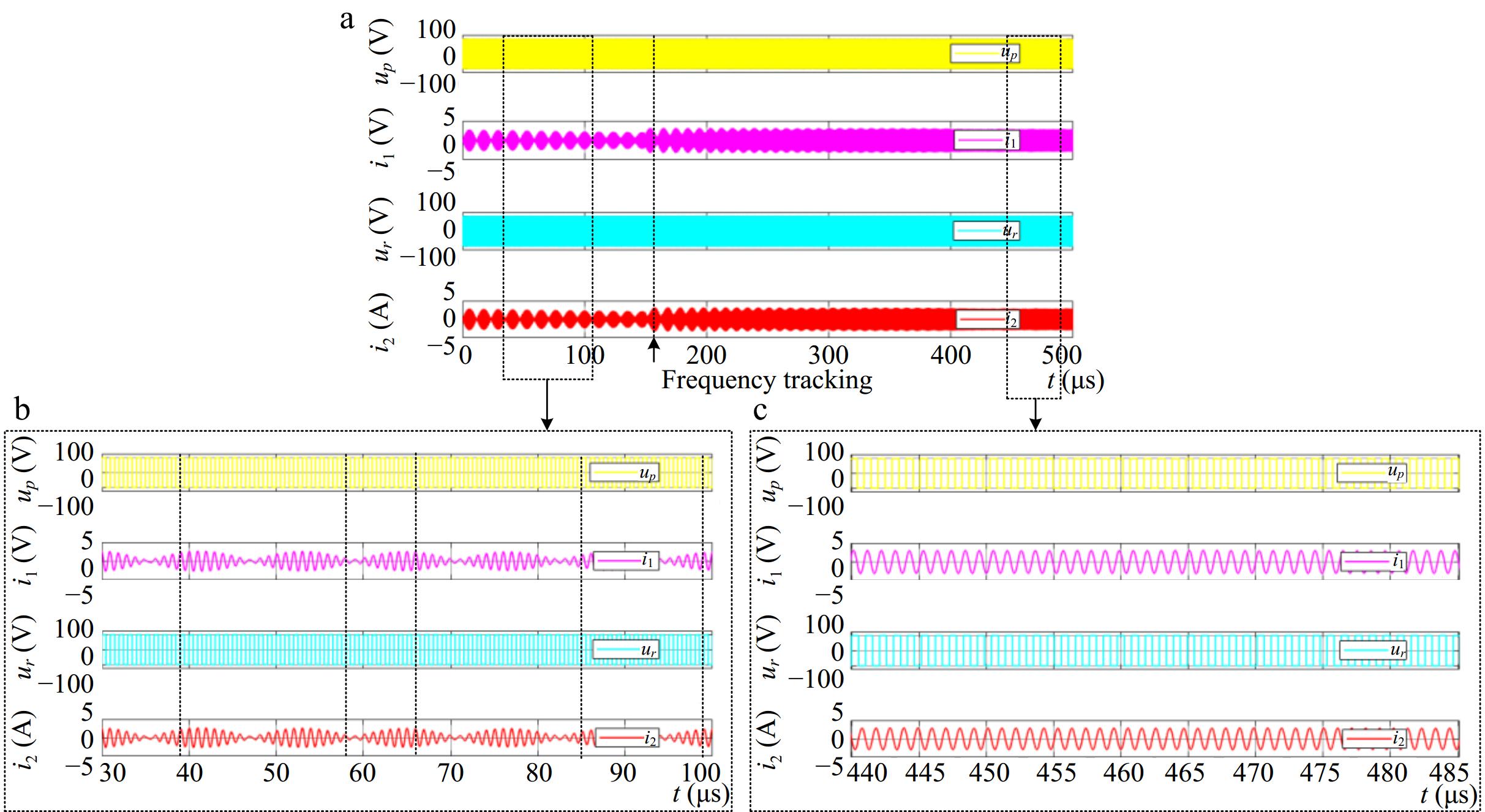
Figure 11.
Resonant voltages and currents generated by the primary and secondary sides of the bidirectional EC-WPT system. (a) Full view of the transient responder. (b) Zoomed-in view of the fixed-frequency driving. (c) Zoomed-in view of the frequency tracking method.
In addition, Fig. 12 shows the simulated waveform of the system output currents. When the primary and secondary converters operate at a fixed initial frequency, the DC output currents of the primary and secondary converters oscillate continuously and periodically. Afterward, the system tracks the zero-crossing points of the resonant currents and drives the converters, the currents gradually stabilize and eventually operate stably at the inherent resonant frequency. Besides, Fig. 13 provides an enlarged view of the trend of the operating frequency of the primary and secondary sides changing from 1 to 0.948 MHz, which is consistent with the theoretical modeling in Fig. 8. It can be seen that the proposed inherent resonant frequency tracking method is effective.
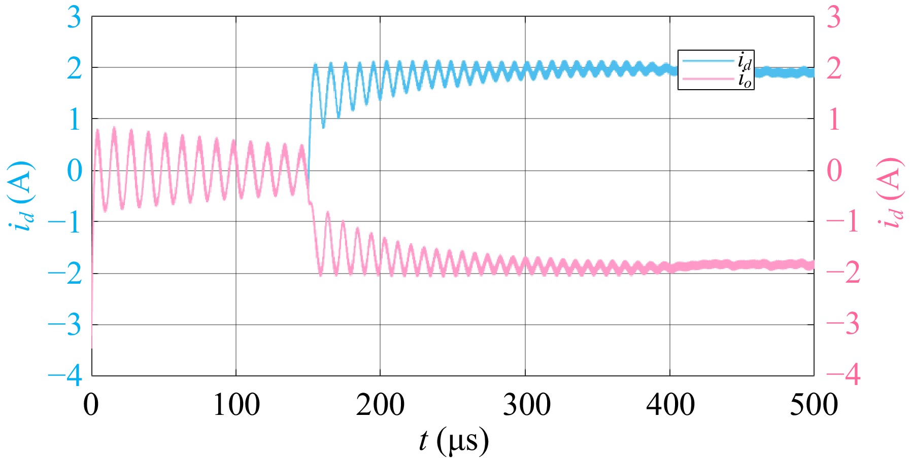
Figure 12.
DC output currents of the primary and secondary sides.
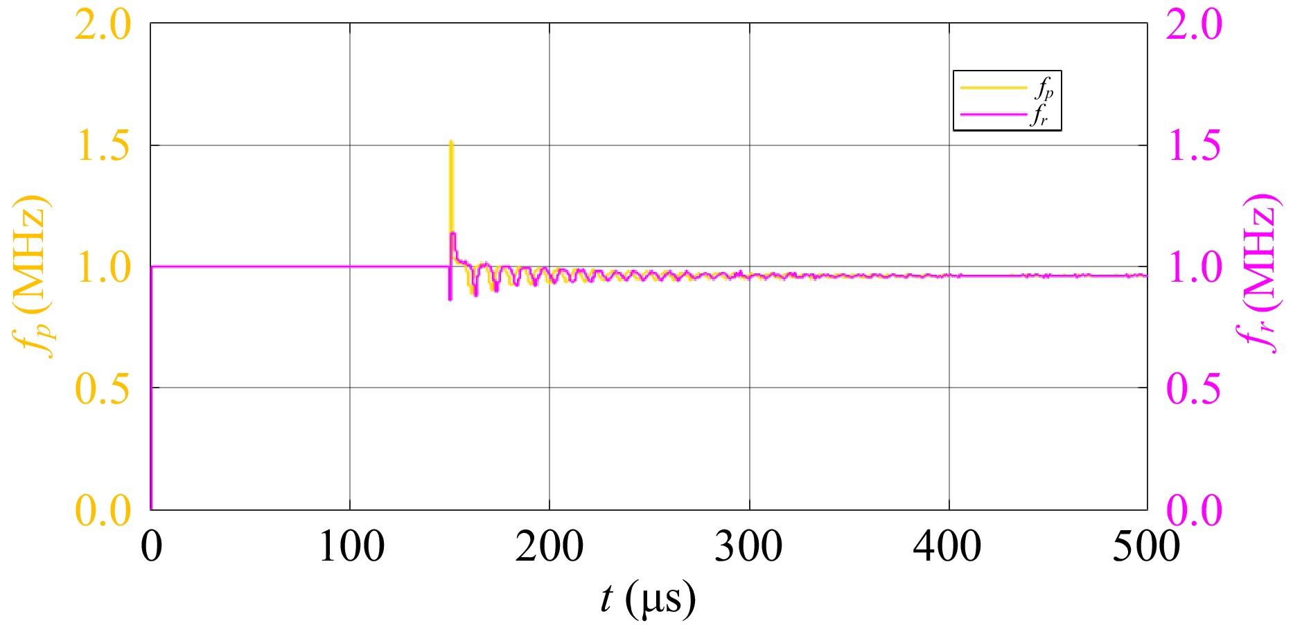
Figure 13.
The operating frequency of the system.
Experimental prototype setup
-
To verify the feasibility of the inherent resonant frequency tracking control method for the bilateral LC-compensated bidirectional EC-WPT system, a 100 W experimental setup was constructed as shown in Fig. 14. The proposed system includes the full-bridge converter of the primary and secondary sides controlled by two controllers. The controller core has been fully encoded with HDL and implemented on the Cyclone II FPGA. The full-bridge converter was implemented with a MHz GaN power module.
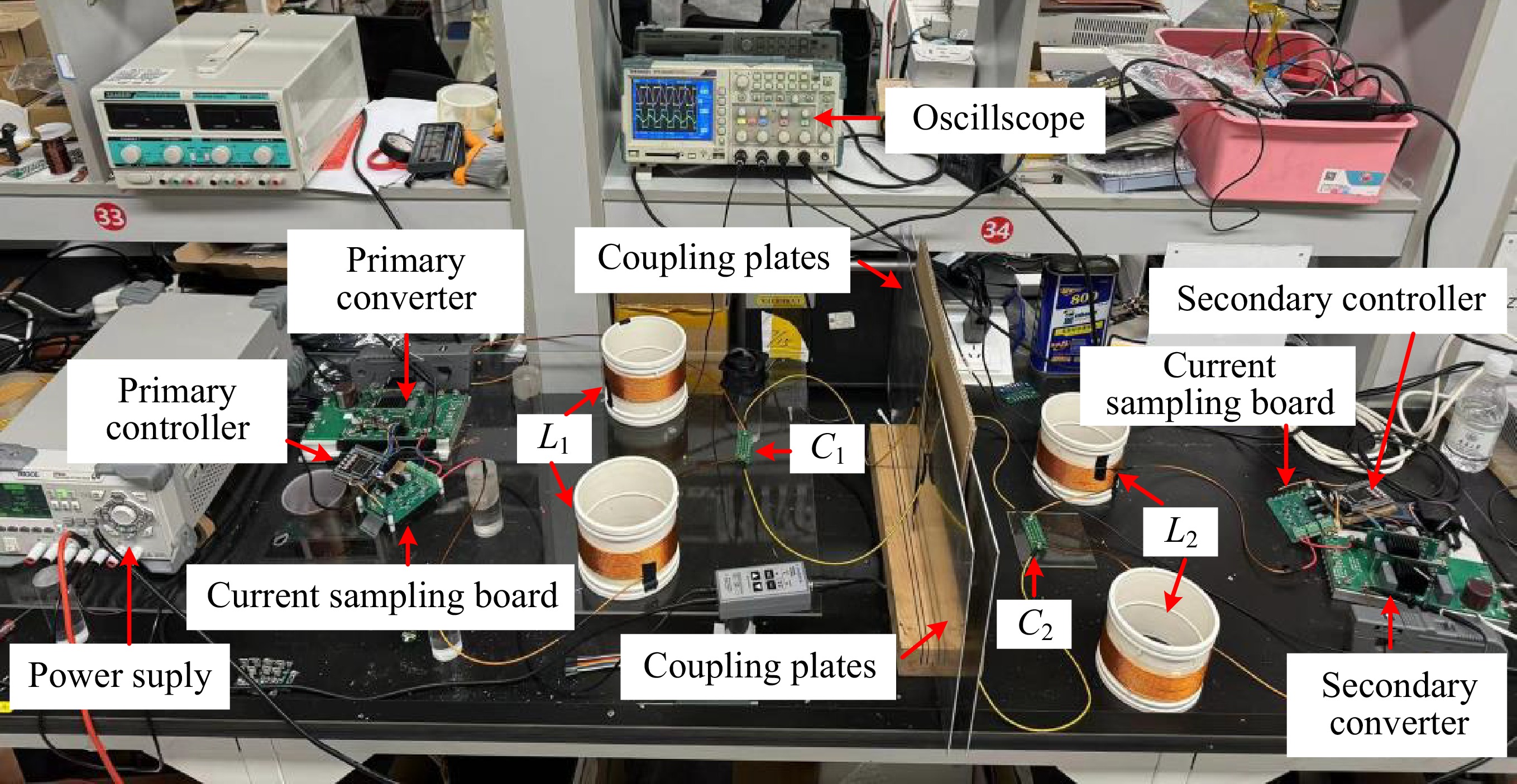
Figure 14.
Experimental prototype of a bilateral LC-compensated bidirectional EC-WPT system.
The frequency detection circuit is designed to sample the resonant currents by a current transformer (CU8965-AL), a differential operational amplifier (AD8058), and a high-speed comparator (TL3016).
The circuit parameters of the experimental prototype are designed symmetrically from the primary to the secondary side and are summarized in Table 3. High voltage multilayer surface mount device (SMD) ceramic capacitors were used for the parallel resonant capacitors. The compensating inductors L1 and L2 were made of Litz wire wound on a PVC pipe, and obtained from the resonance relation in Eqn (6) at a resonant frequency of 1 MHz.
Inherent resonant frequency tracking control
-
Since the DC input voltage does not affect the inherent resonant frequency of the system, the experiment is given with an input voltage of 30 V. Taking the transmission distance of 10 mm as an example, the experimental waveforms of the proposed inherent resonant frequency tracking method are shown in Fig. 15. Figure 15a is a complete transient view from fixed-frequency driving to frequency tracking. When the primary and secondary converters are driven at a fixed frequency of 1 MHz, the resonant currents of the primary and secondary sides oscillate periodically. The enlarged views are shown in Fig. 15b & c. Figure 15d is an enlarged view of the inherent resonant frequency tracking stage in Fig. 15a & b, showing that the resonant currents of the primary and secondary sides of the system remain stable after driving the converters through following the zero-crossing points of the resonant currents, the resonant voltage and resonant current of the primary sides are in phase (the direction of i1 in Fig. 15 is opposite to that in Fig. 9), and the resonant voltage and resonant current of the secondary sides are out of phase.
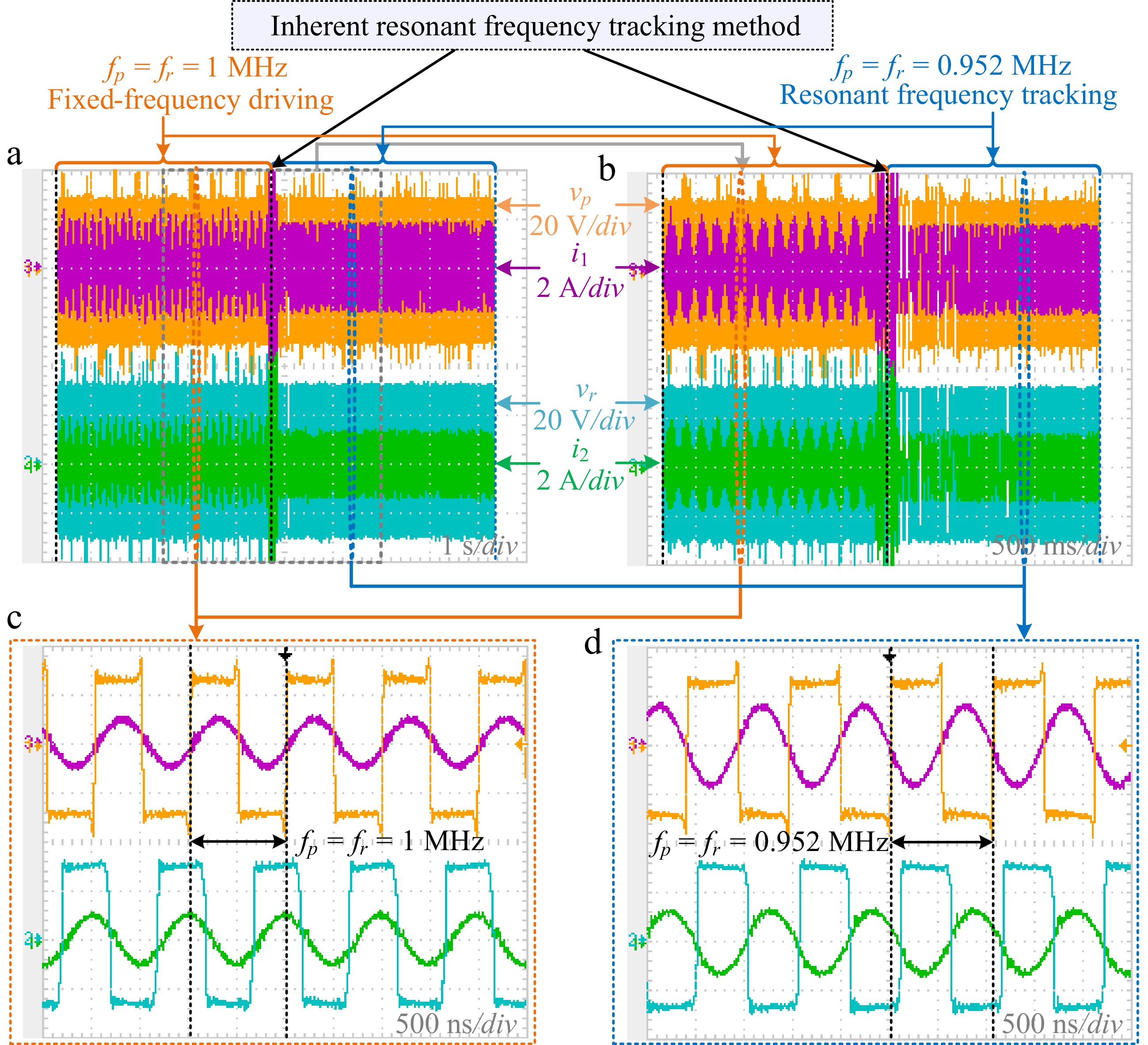
Figure 15.
Resonant voltages and currents generated by the primary and secondary converters. (a) Full view of the transient responder. (b) Zoomed-in view of the transient responder (c) Zoomed-in view of the fixed-frequency driving. (d) Zoomed-in view of thefrequency tracking method.
At this time, the operating frequency of the system is stable at the resonant frequency of 0.952 MHz, which is roughly consistent with the resonant frequency of 0.948 MHz at the maximum amplitude gain of the system shown in Fig. 13. The slight difference is mainly due to differences in system parameters, which can prove the consistency between theoretical modeling, simulation analysis, and experimental results.
-
This paper proposed an inherent resonance frequency dynamic tracking method to address the misalignment of the coupling plates in a dual LC-compensated bidirectional EC-WPT system. The main contributions of the proposed method are as follows:
(1) The method can effectively tolerate the issue of misalignment of coupling plates in a bidirectional EC-WPT system and provide an effective resonant frequency tracking strategy.
(2) The method can autonomously track the inherent resonant frequency of the bidirectional EC-WPT system, providing support for the application and development of a dynamic system.
(3) The method has a simple circuit design, is easy to implement, and is beneficial for the operation of high-frequency bidirectional EC-WPT systems.
This work was supported by the National Natural Science Foundations of China (Grant No. 52277003), Open Project of Key Laboratory of Electromechanical Equipment Security in Western Complex Environment for State Market Regulation (Grant No. CQTJ-XBJD-KFKT202203), and Fundamental Research Funds for the Central Universities (Grant No. 2024CDJXY027).
-
The authors confirm contribution to the paper as follows: study conception and design: Sun M, Dai X; data collection: Sun M, Wang L, Kang D; analysis and interpretation of results: Sun M, Lv X; draft manuscript preparation: Sun M. All authors reviewed the results and approved the final version of the manuscript.
-
The data that support the findings of this study are available from the corresponding author upon reasonable request.
-
The authors declare that they have no conflict of interest. Xin Dai is the Editorial Board member of Wireless Power Transfer who was blinded from reviewing or making decisions on the manuscript. The article was subject to the journal's standard procedures, with peer-review handled independently of this Editorial Board member and the research groups.
- Copyright: © 2025 by the author(s). Published by Maximum Academic Press, Fayetteville, GA. This article is an open access article distributed under Creative Commons Attribution License (CC BY 4.0), visit https://creativecommons.org/licenses/by/4.0/.
-
About this article
Cite this article
Sun M, Dai X, Wang L, Kang D, Lv X. 2025. Inherent resonance frequency dynamic tacking method with misalignment of coupling plates for the bidirectional EC-WPT system. Wireless Power Transfer 12: e004 doi: 10.48130/wpt-0025-0002 

Inherent resonance frequency dynamic tacking method with misalignment of coupling plates for the bidirectional EC-WPT system
- Received: 01 January 2024
- Revised: 07 November 2024
- Accepted: 06 December 2024
- Published online: 21 February 2025
Abstract: A bidirectional Electrical Coupled Wireless Power Transfer (EC-WPT) system is suitable for energy interaction between grid and electric vehicles, or electronic devices. Typically, the magnitude and direction of the power are controlled by the amplitude or phase angle of the voltages generated by the converters. However, misalignment of the coupling plates and variation of the transmission distance are an inevitable issue in wireless charging systems based on bidirectional EC-WPT technology. A change in the coupling capacitances will cause a deviation in the magnitude and transmission direction of power. This paper proposes an inherent resonance frequency dynamic tracking method to address coupling misalignment, ensuring accurate and effective power flow transmission. The method establishes a dynamic multivariate state-space model of the bidirectional EC-WPT system, calculates the transfer function matrix of the fourth-order system, analyzes the amplitude-frequency characteristics, obtains the frequency corresponding to the maximum gain, and proposes an inherent frequency dynamic tracking method for autonomously driving the bilateral converters by zero-crossing detecting the resonant currents on the primary and the secondary sides. Finally, an experimental setup of the bidirectional EC-WPT system is established, and the experimental results verify the feasibility and effectiveness of the proposed frequency tracking method for misalignment toleration of the coupling plates.