-
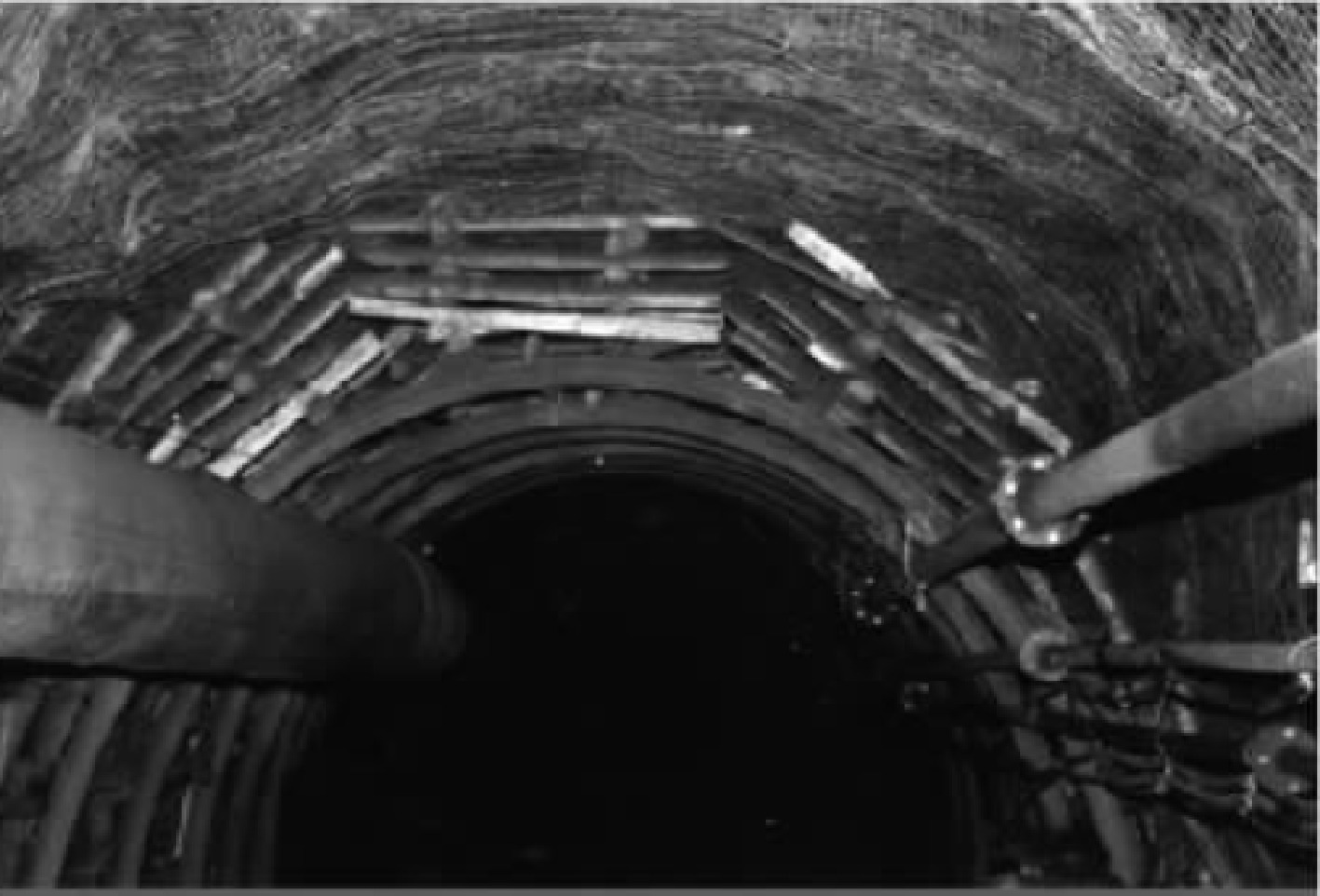
Figure 1.
Deep rock mass roadway support before impact ground pressure failure.
-
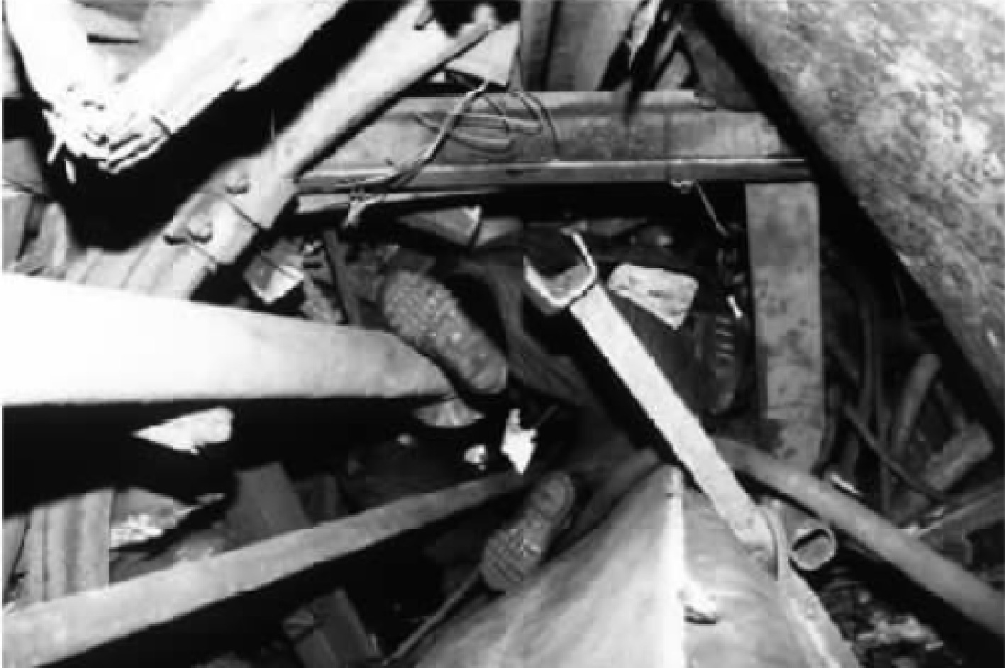
Figure 2.
Deep rock mass roadway support after impact ground pressure failure.
-
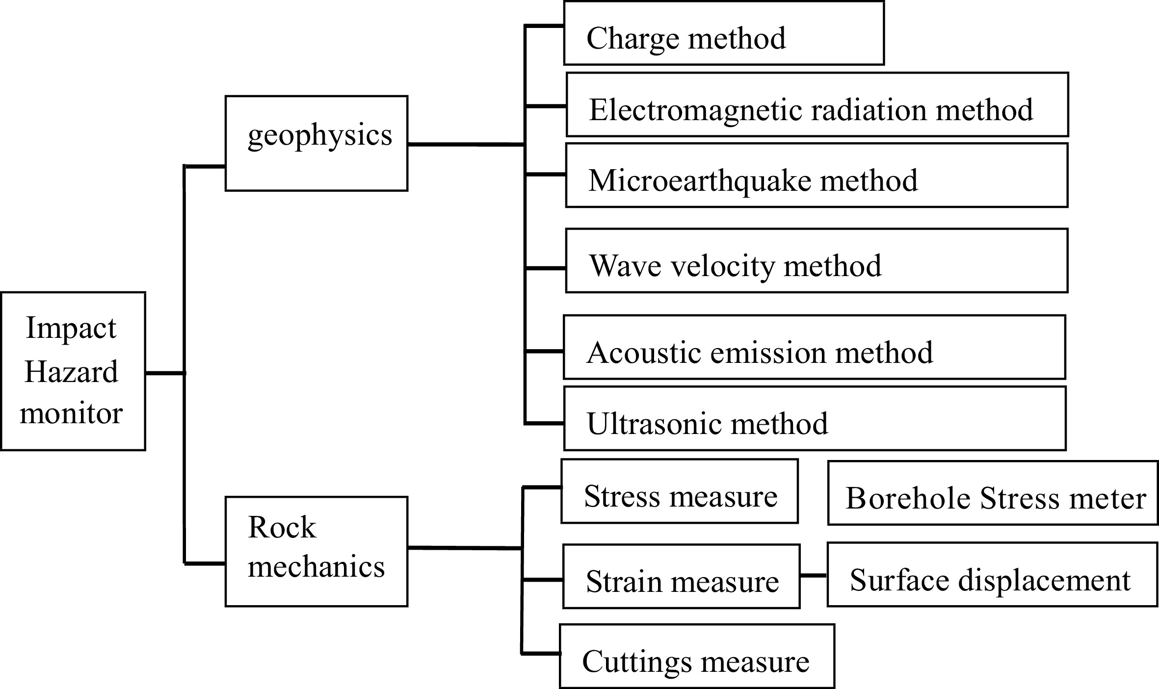
Figure 3.
Various monitoring methods for impact ground pressure.
-
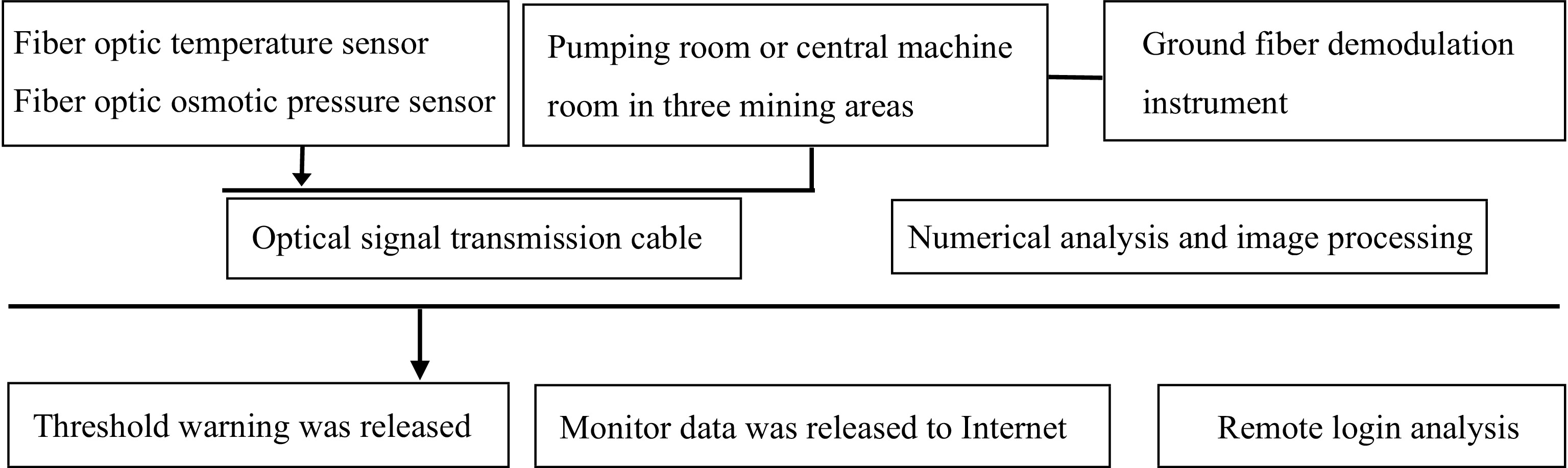
Figure 4.
Deep roadway water inrush monitoring system principles.
-
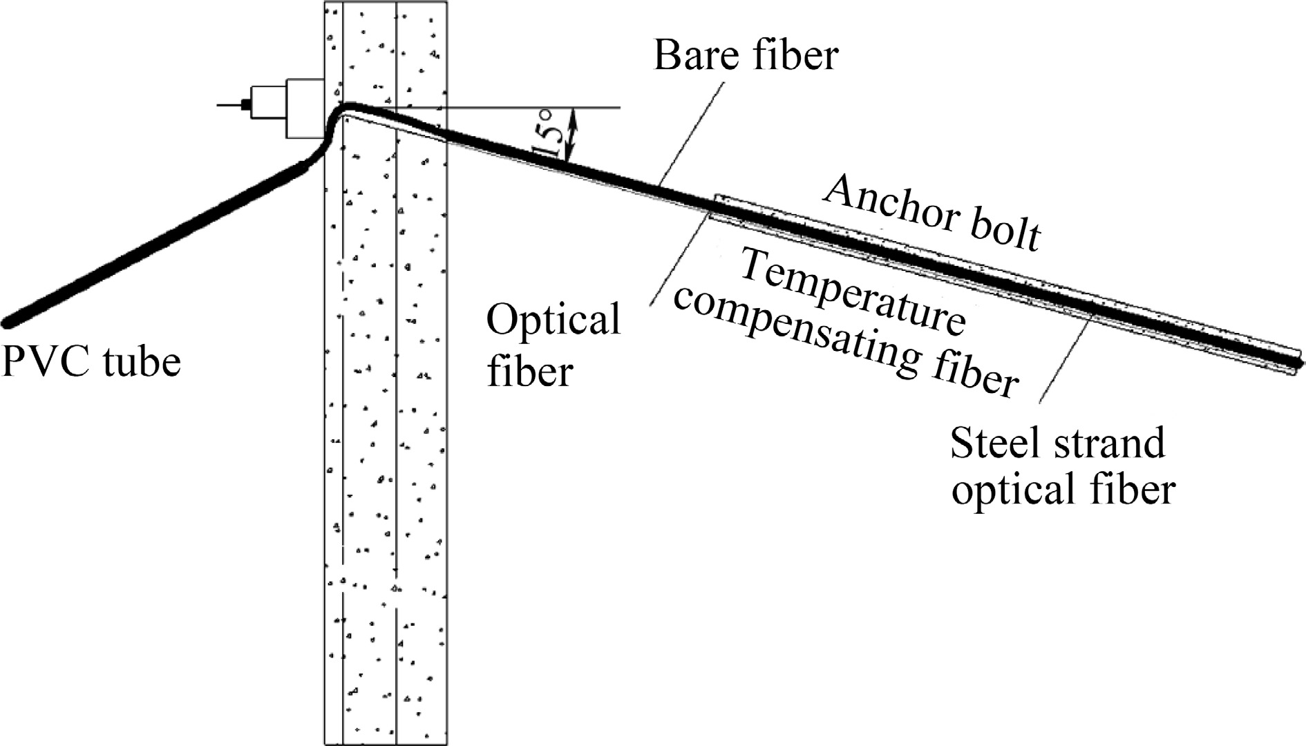
Figure 5.
The installation diagram of distributed optical fiber in the anchor rod.
-
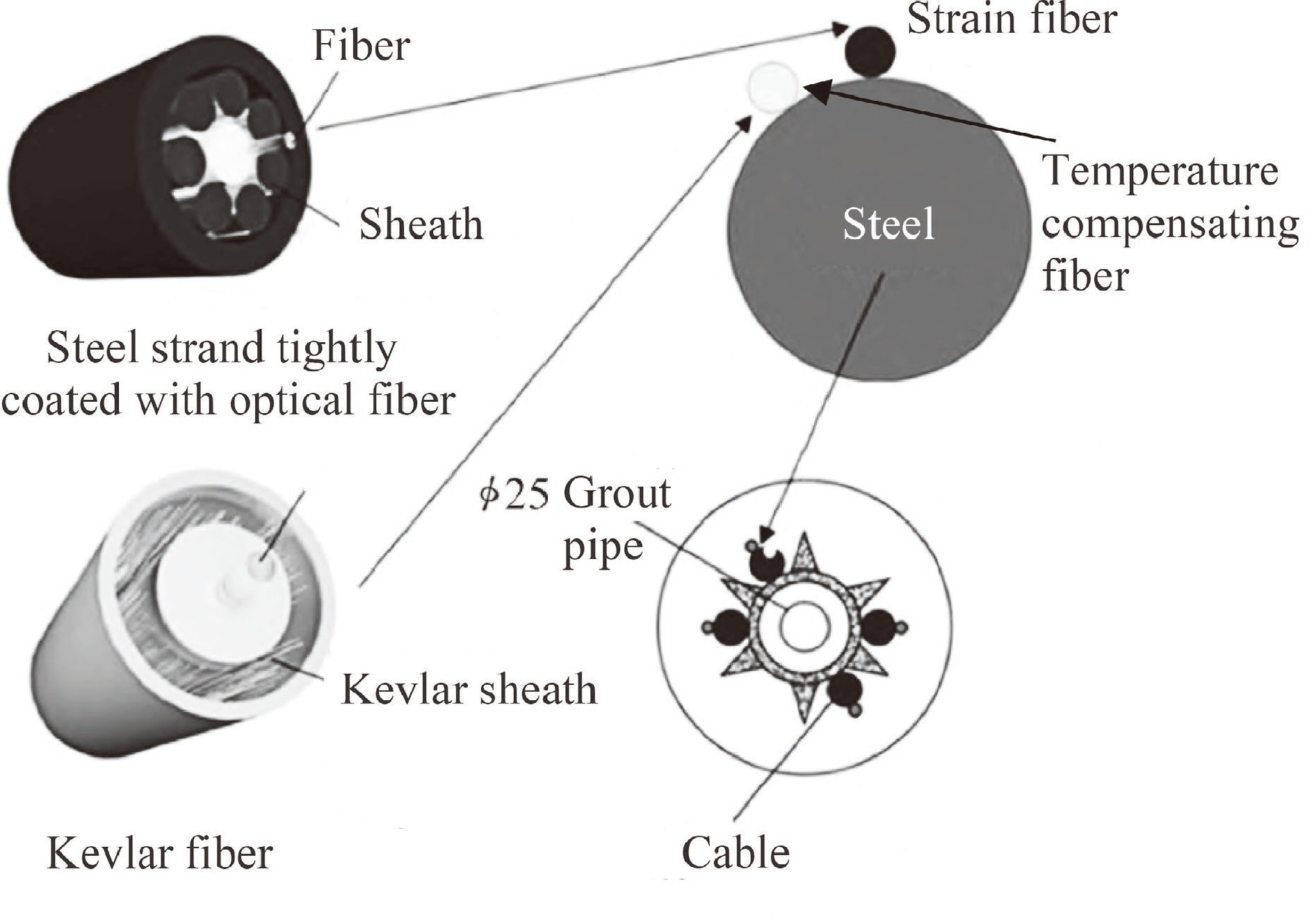
Figure 6.
Detailed structure diagram of fiber optic anchor bar.
-
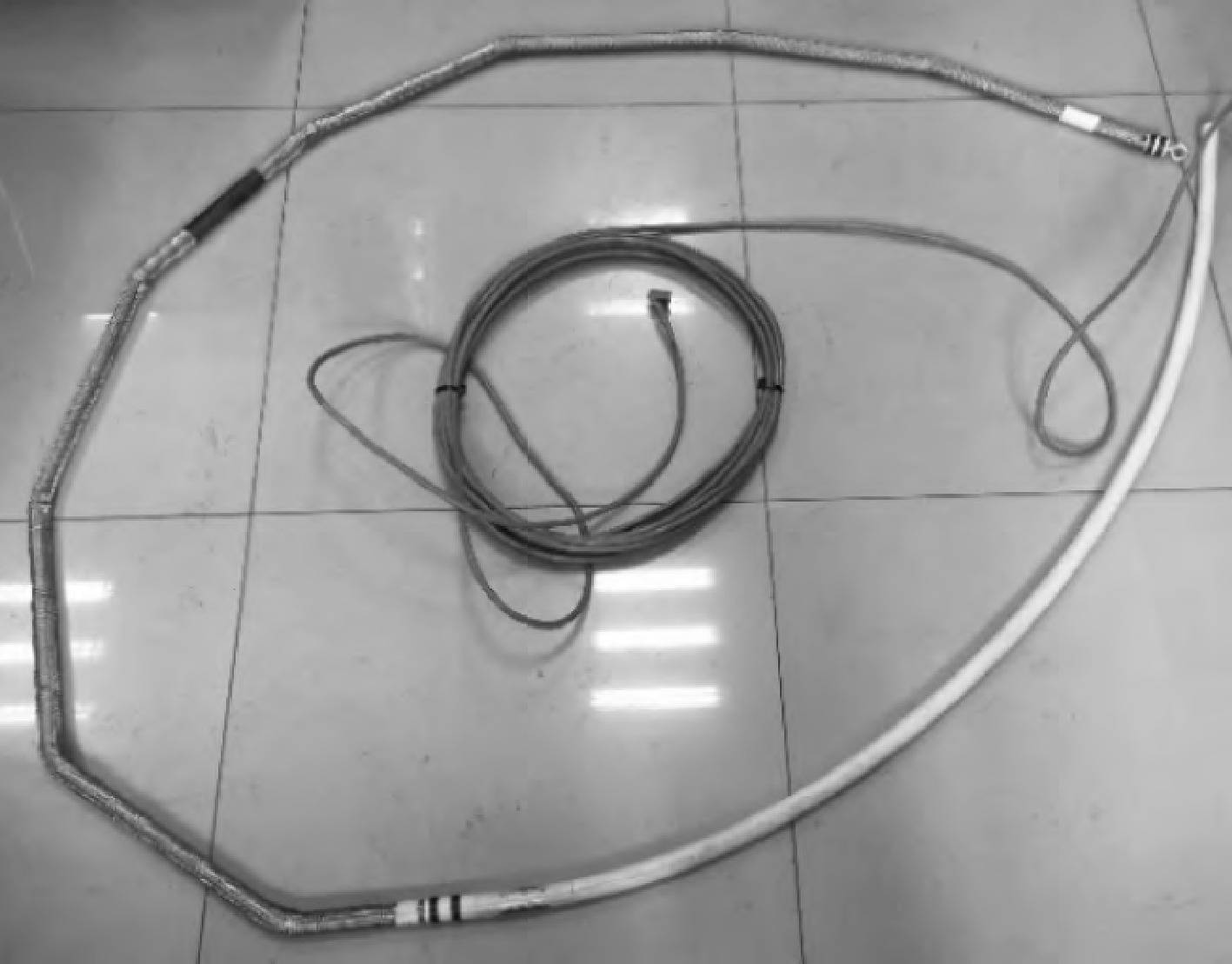
Figure 7.
Strain annular array displacement sensor.
-
Monitor items Maximum
valueRate
warning
(mm/d)Control
valueWall displacement (mm) Supporting pile 1 3 35 Supporting axial force (kN) Supporting axial force 1 13,777 Water table (mm) Water table 1 2,000 Column settlement (mm) Column 1 2 20 Ground displacement (mm) Ground 1 3 35 Horizontal displacement of supporting pile (mm) Pile 3 20 Vertical displacement of supporting pile (mm) Pile 3 20 Table 1.
Monitoring items and limits for excavation engineering.
Figures
(7)
Tables
(1)