-
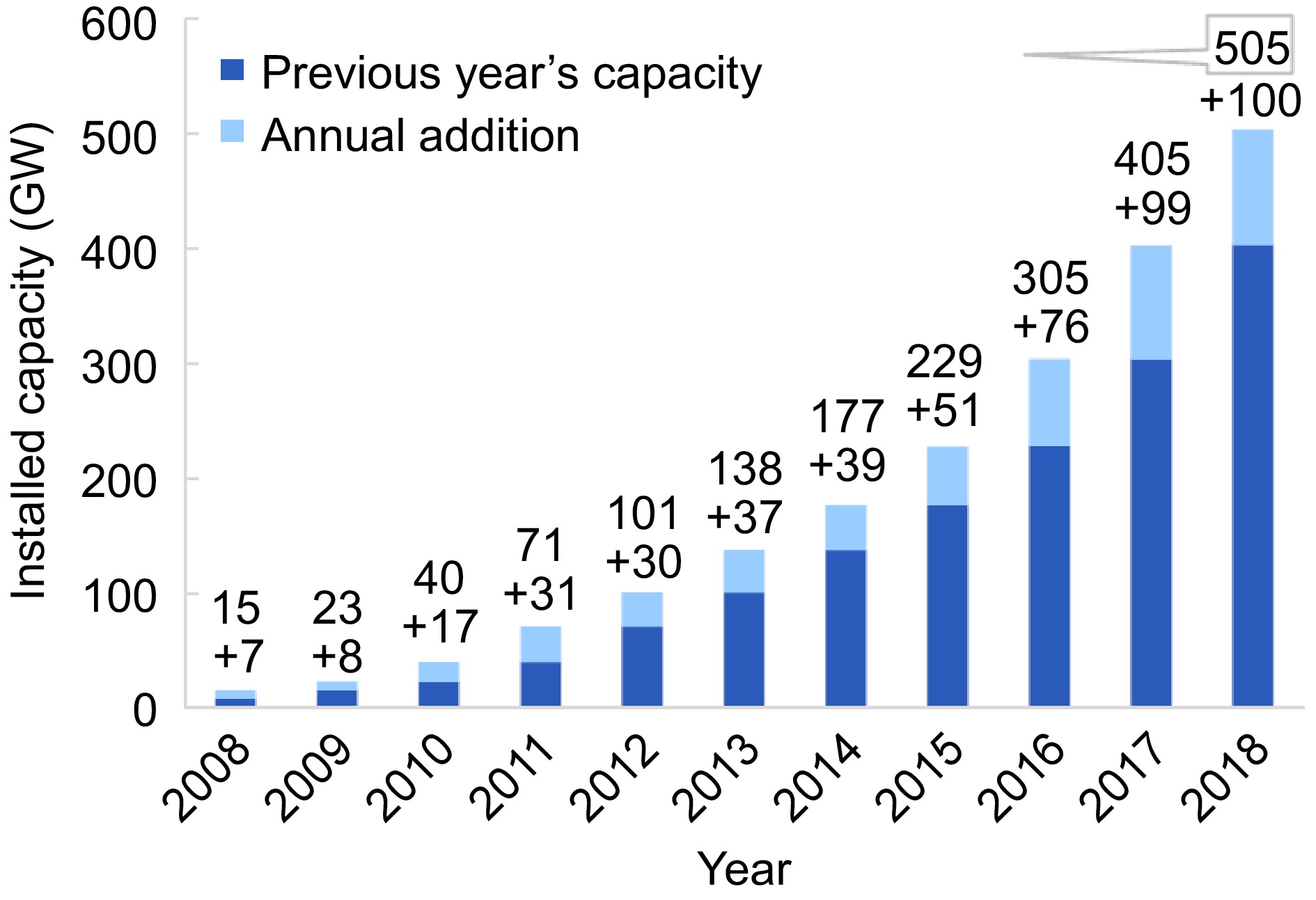
Figure 1.
Overall constructed solar energy production from 2008 to 2018[14].
-
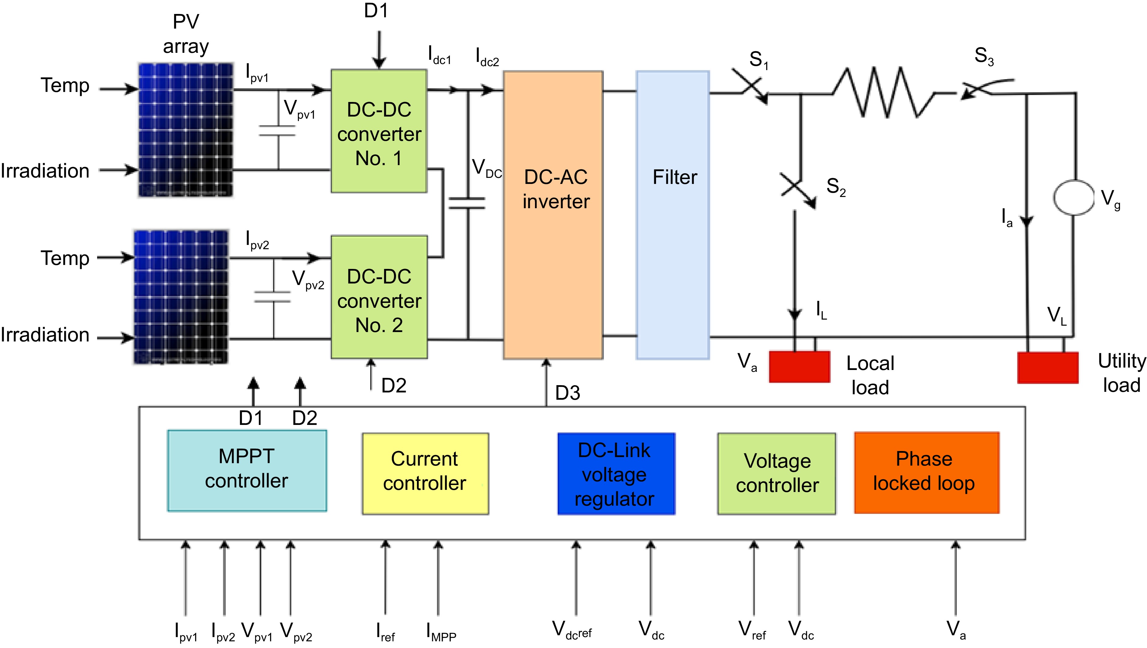
Figure 2.
Overall system design[76].
-
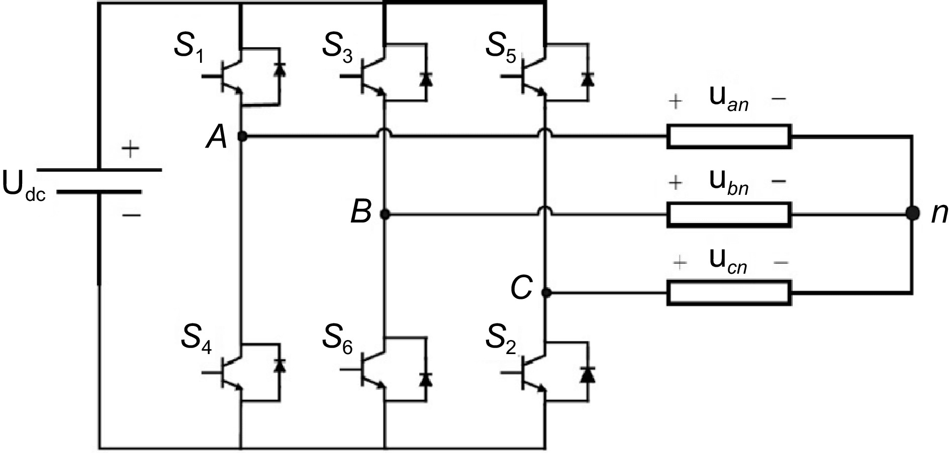
Figure 3.
Three phase voltage source inverter.
-
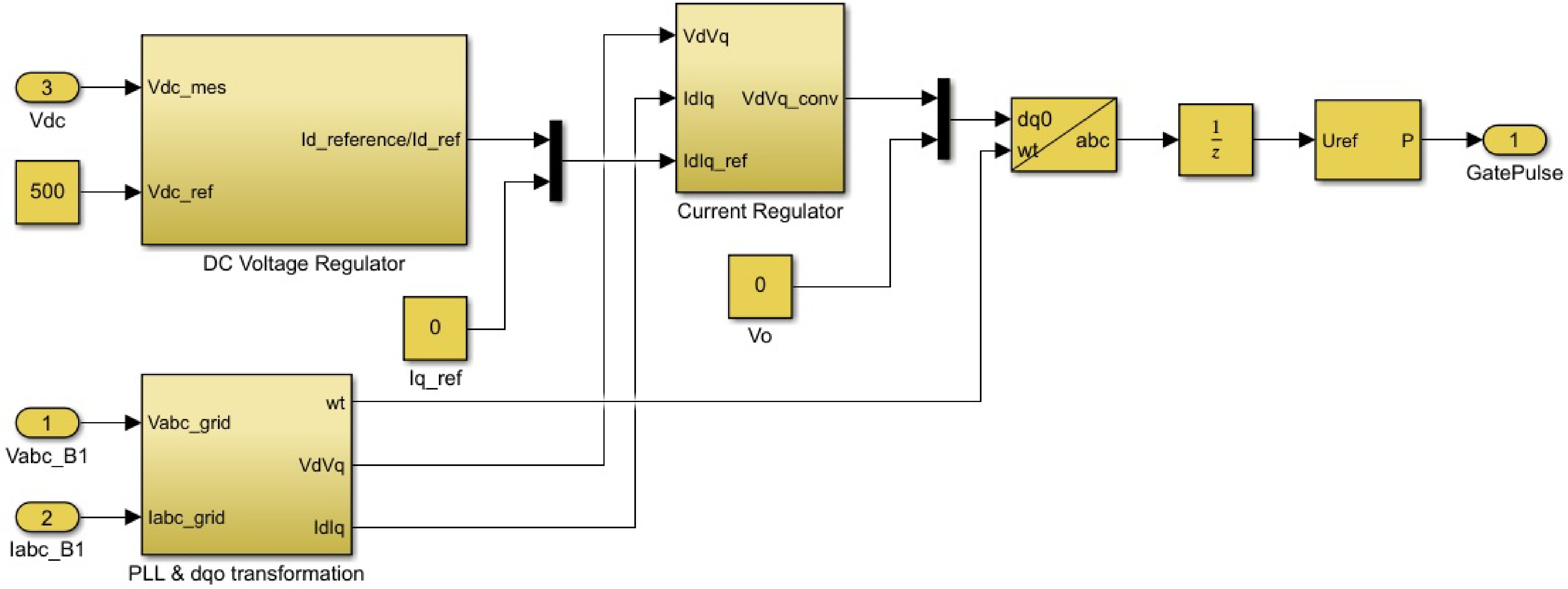
Figure 4.
Design of the optimal controller.
-
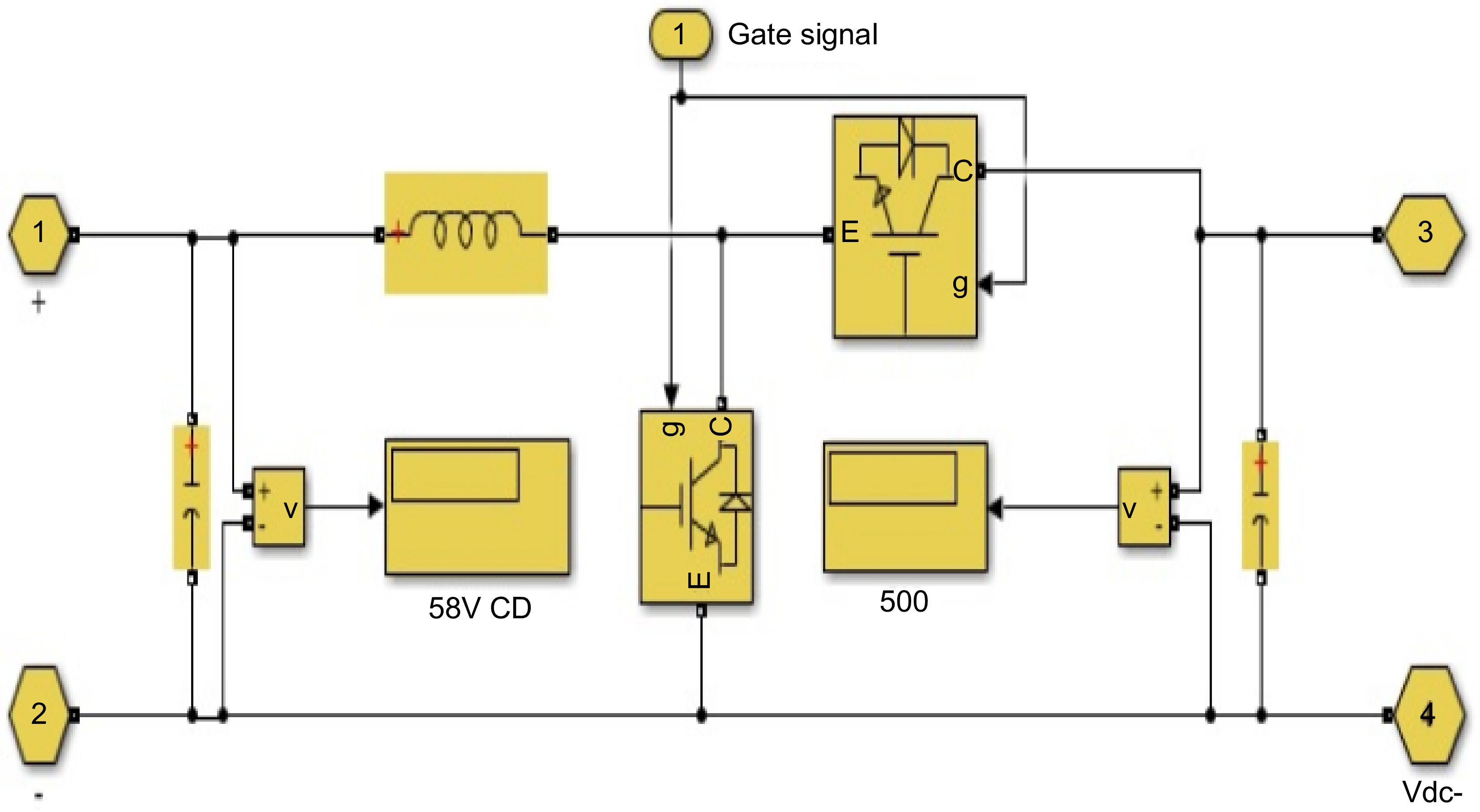
Figure 5.
Design of bidirectional DC-DC converter.
-
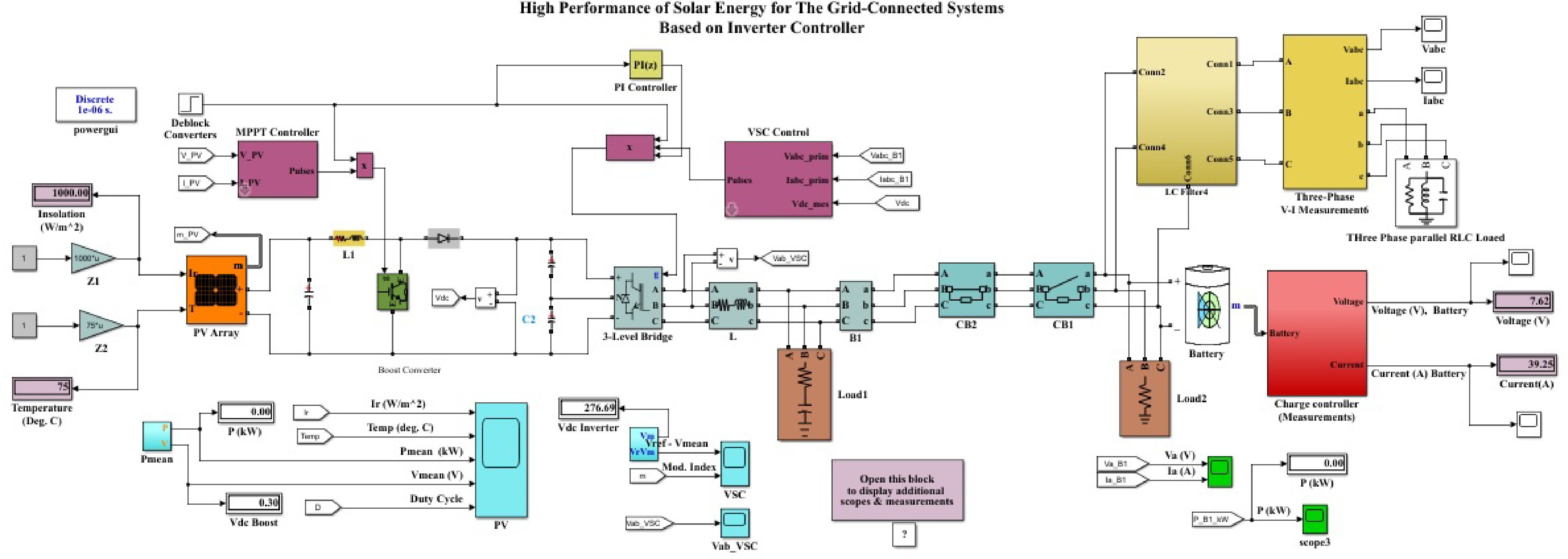
Figure 6.
The overall system of solar energy for the grid-connected systems based on optimal controller.
-
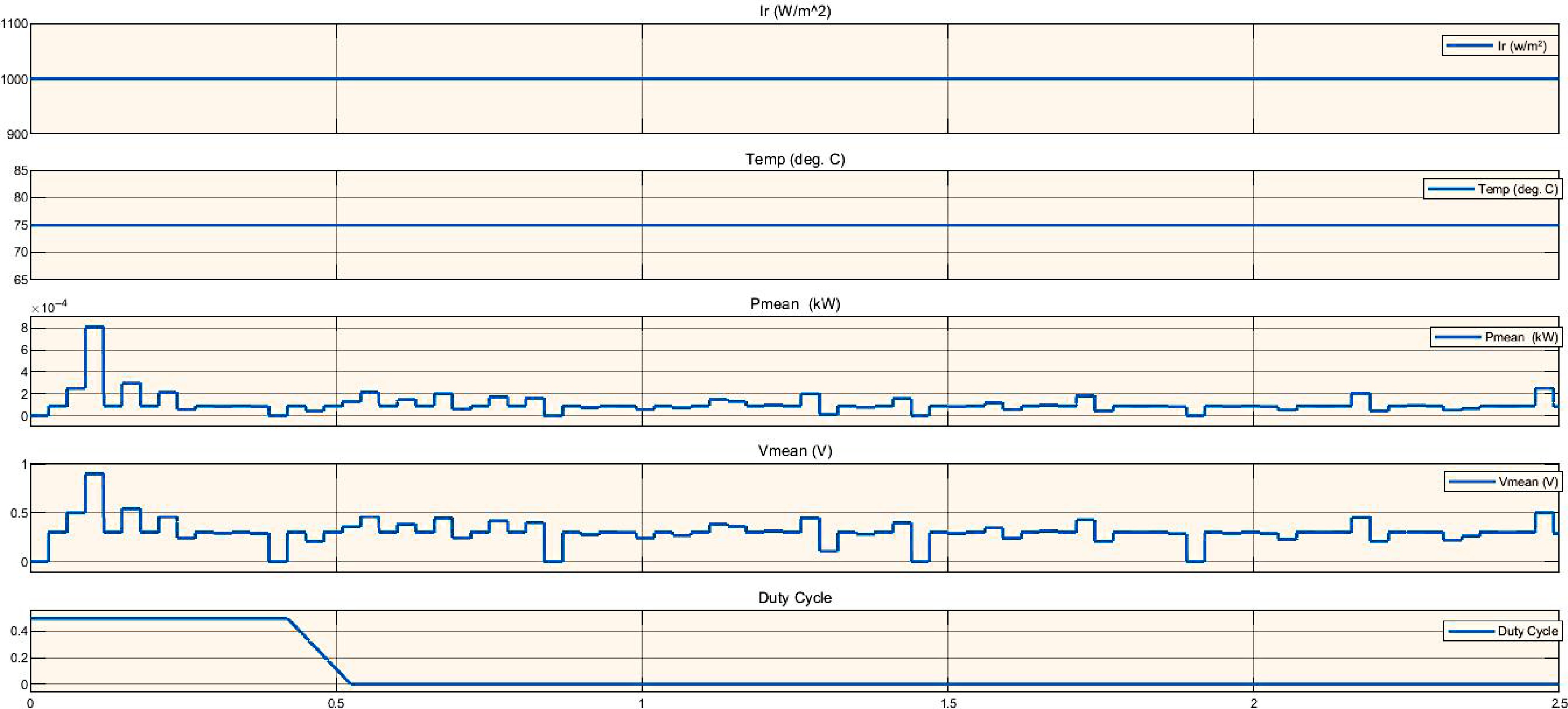
Figure 7.
Simulation of PV system analysis based on irradiance affect.
-
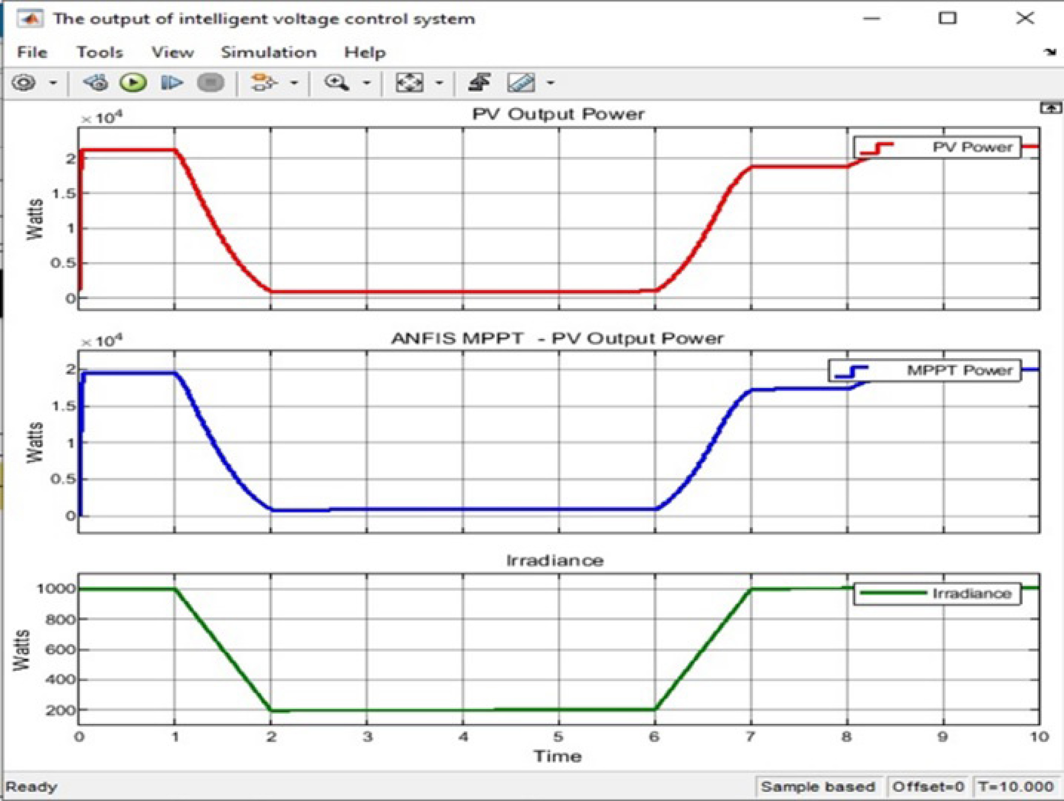
Figure 8.
The output ANFIS controller based on MPPT.
-
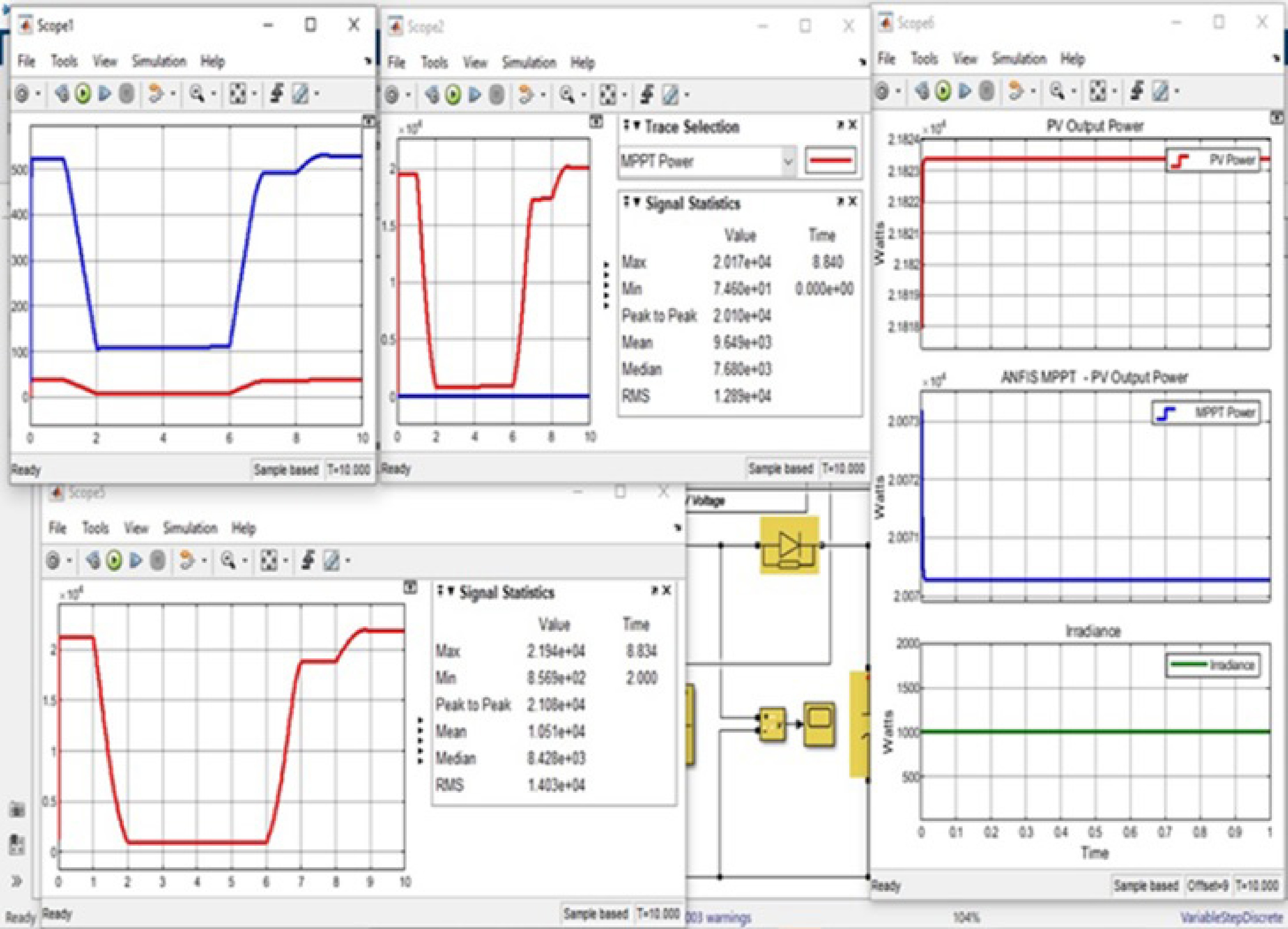
Figure 9.
Overall simulation for optimal controller of solar energy with grid-connected systems.
-
Ref. NOP, CRF CC DLC FL CP F MT A [60] 3-PH DP, PI DB M-L C, V LCL DPWM G [61] 3-PH Active recative control PI, PR M-L V, P L PWM G [62] 3-PH MPC − S-L V, C L PWM PV [63] 3-PH MPC − S-L C LCL PWM G [64] 3-PH Fuzzy PI M-L V, C L SVPWM PV [65] 1-PH Fractional order PR − M-L C, P L SPWM PV [66] 3-PH Fractional order PI Fractional order PR M-L V, C LCL PWM PV [67] 3-PH PI PI M-L V, C LCL PWM PV [68] 3-PH PR PI M-L V, C LCL PWM PV [69] 1-PH FuzzySMC − S-L V L PWM PV [70] 3-PH PI PI M-L V, C L SVPWM PV [71] 1-PH PI, MPC PI, MPC M-L V, C L PWM PV [72] 3-PH PI, Vector control PI M-L V, C L PWM PV [73] 3-PH Fractional order SMC − S-L C L PWM PV [74] 3-PH MPC − S-L C LCL PWM G [75] 1-PH Fractional order RC − S-L C LCL PWM G NOP: Number of Phases, CRF: Control Reference Frames, CC: Current Controller, DLC: DC-Link Controller, FL: Feedback Loop, CP: Control Parameters, F: Filter, MT: Modulation Technique, A: Application, M-L: Multiple loop, S-L: Single loop, V: Voltage, C: Current, P: Power, and G: General. Table 1.
Key features of various controllers suggested in scholarly works.
-
Details Value Grid line voltage (V L-L) 415 V Grid phase voltage (Vph) 240 V DC source voltage (Vdc) 250 V Output power fed to grid (Pn) 1,000 W Grid Frequency (f) 50 Hz Switching frequency (fs) 20 KHz Table 2.
Design parameters.
Figures
(9)
Tables
(2)