-
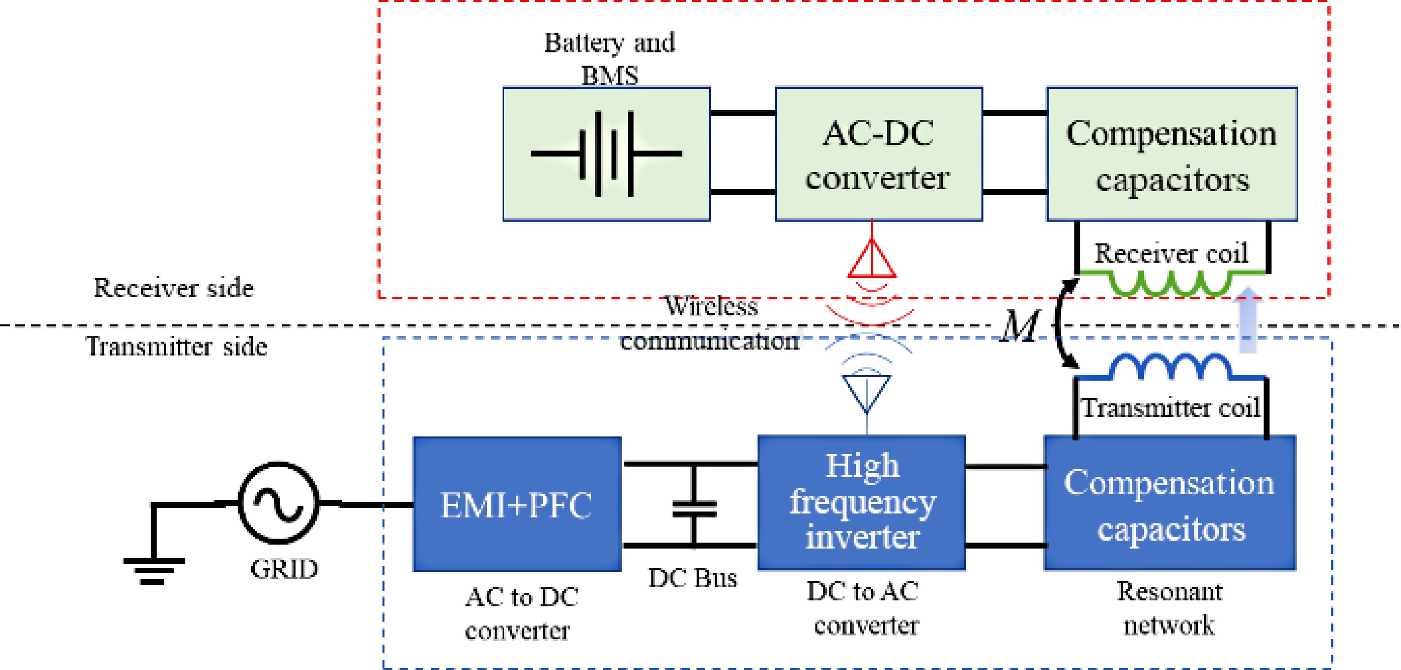
Figure 1.
Block diagram of RIPT based wireless charger.
-
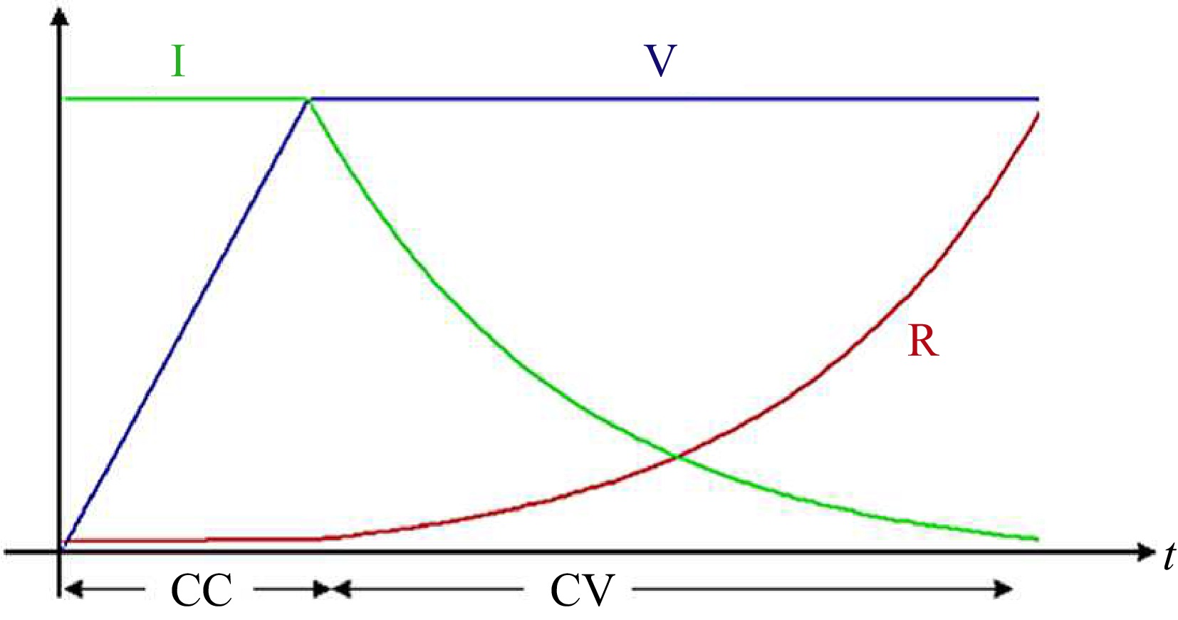
Figure 2.
CC-CV charging operation.
-

Figure 3.
SS-RIPT based charger.
-

Figure 4.
Simplified equivalent circuit of the SS-RIPT system.
-
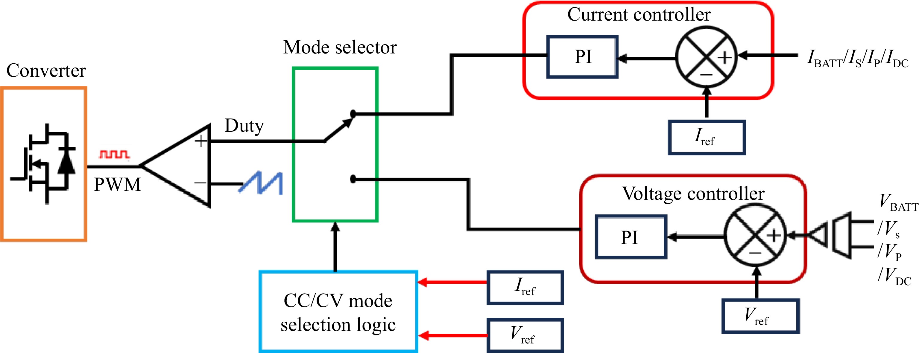
Figure 5.
CC-CV controller.
-
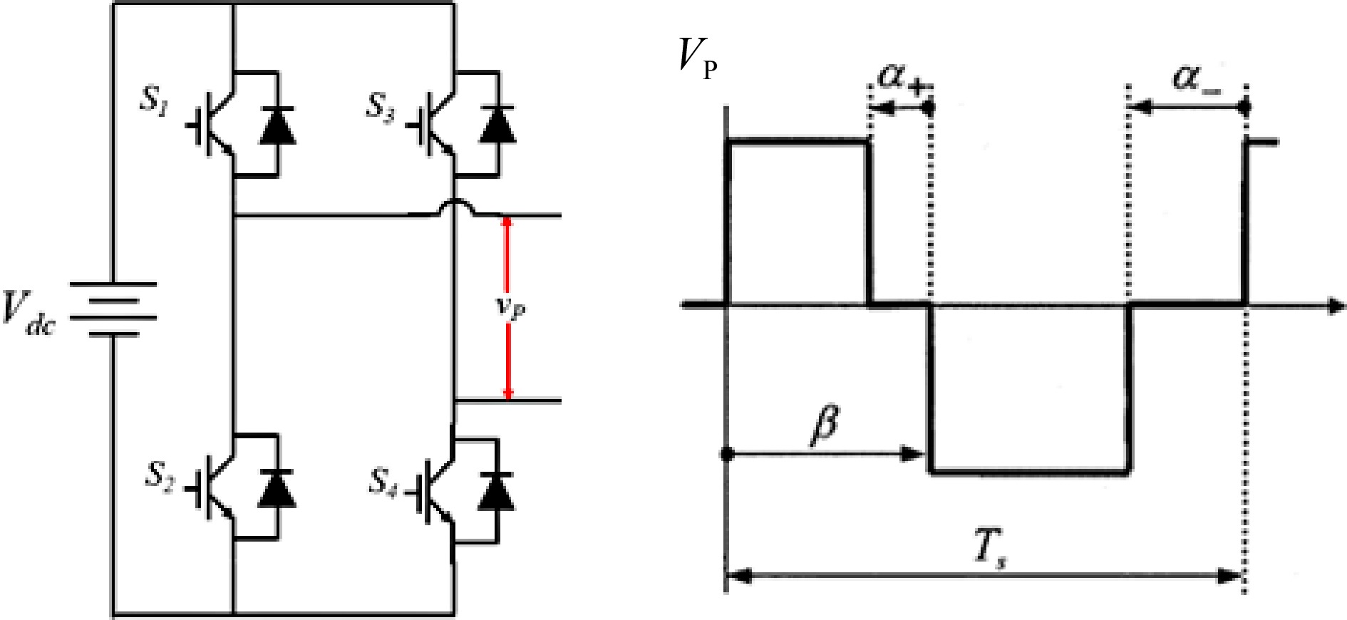
Figure 6.
Quasisquare output voltage waveform of a resonant inverter.
-
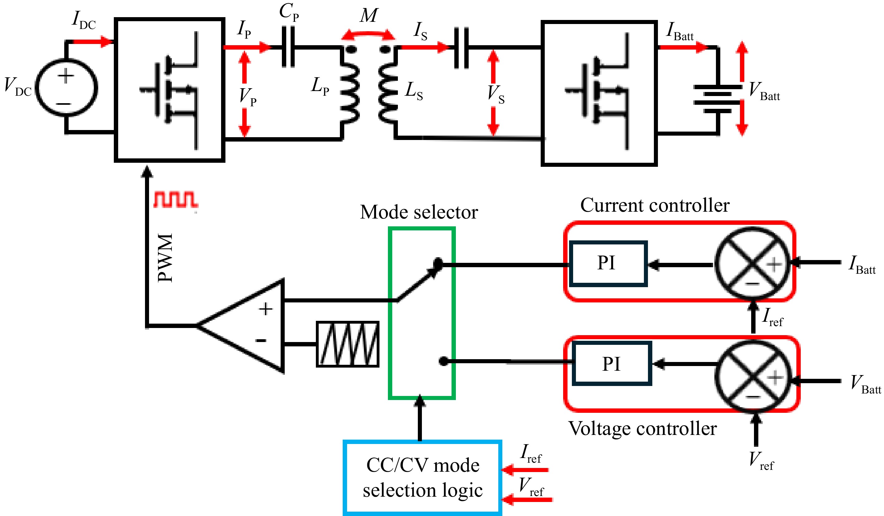
Figure 7.
Primary side direct contro.
-
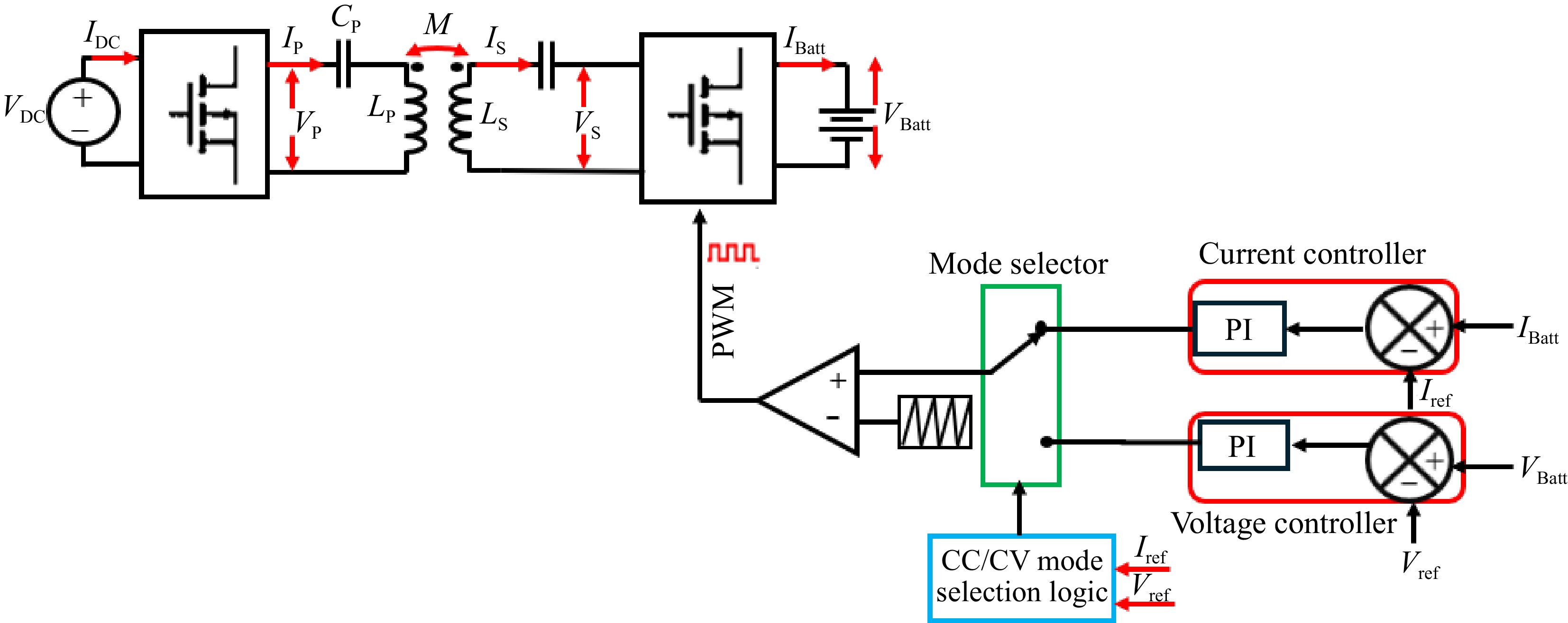
Figure 8.
Secondary side direct control.
-
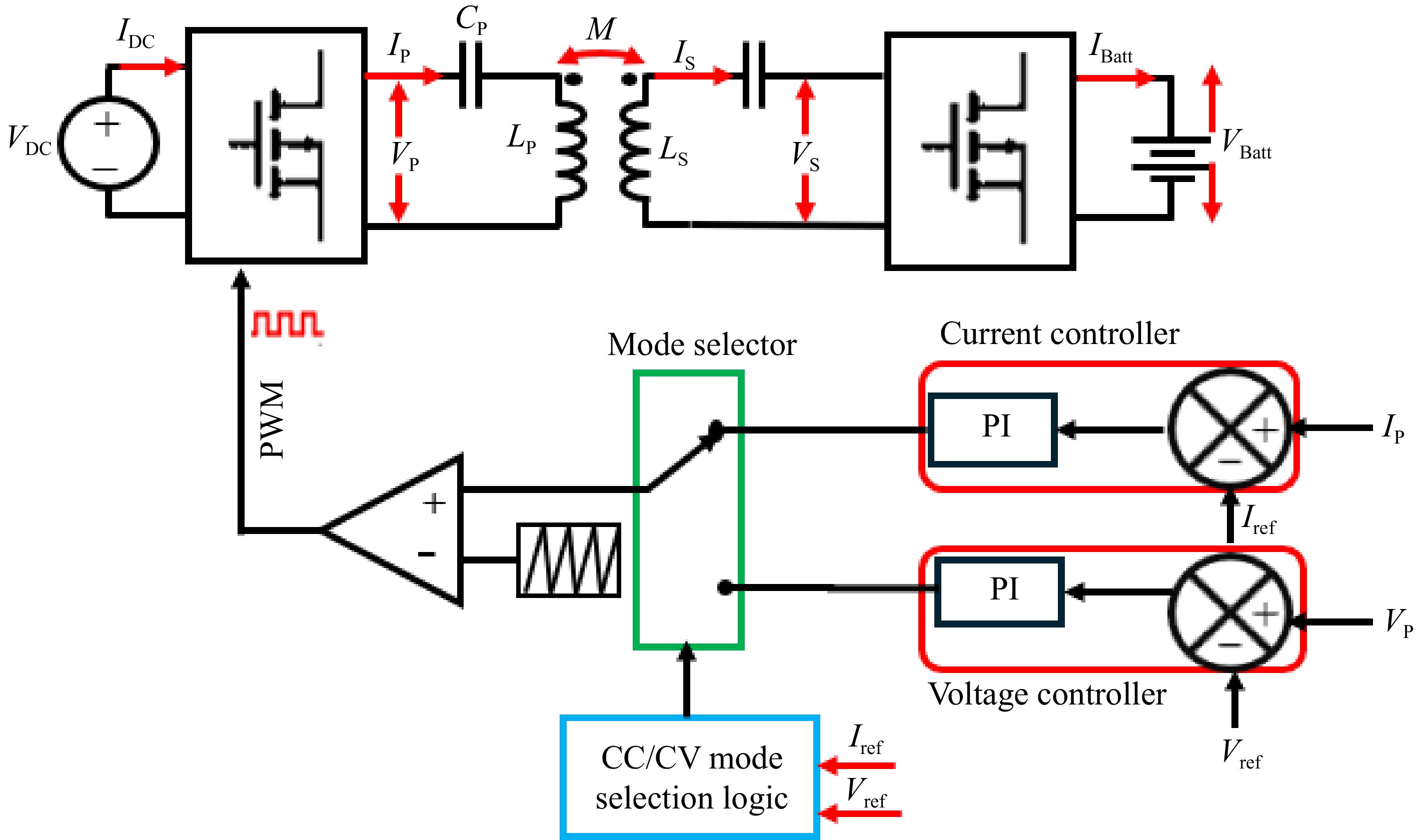
Figure 9.
Primary side indirect control.
-

Figure 10.
Inverter output voltage regulation based on duty cycle control.
-
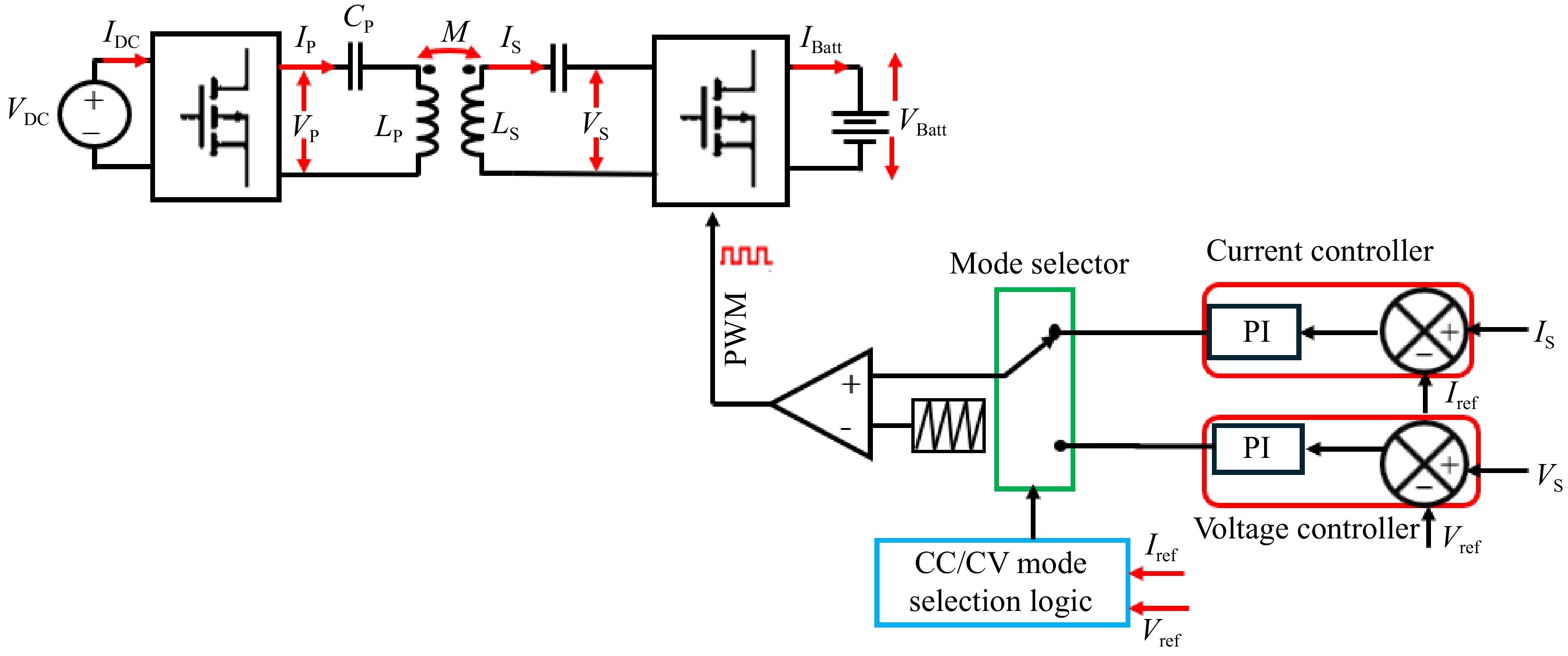
Figure 11.
Secondary side indirect control.
-
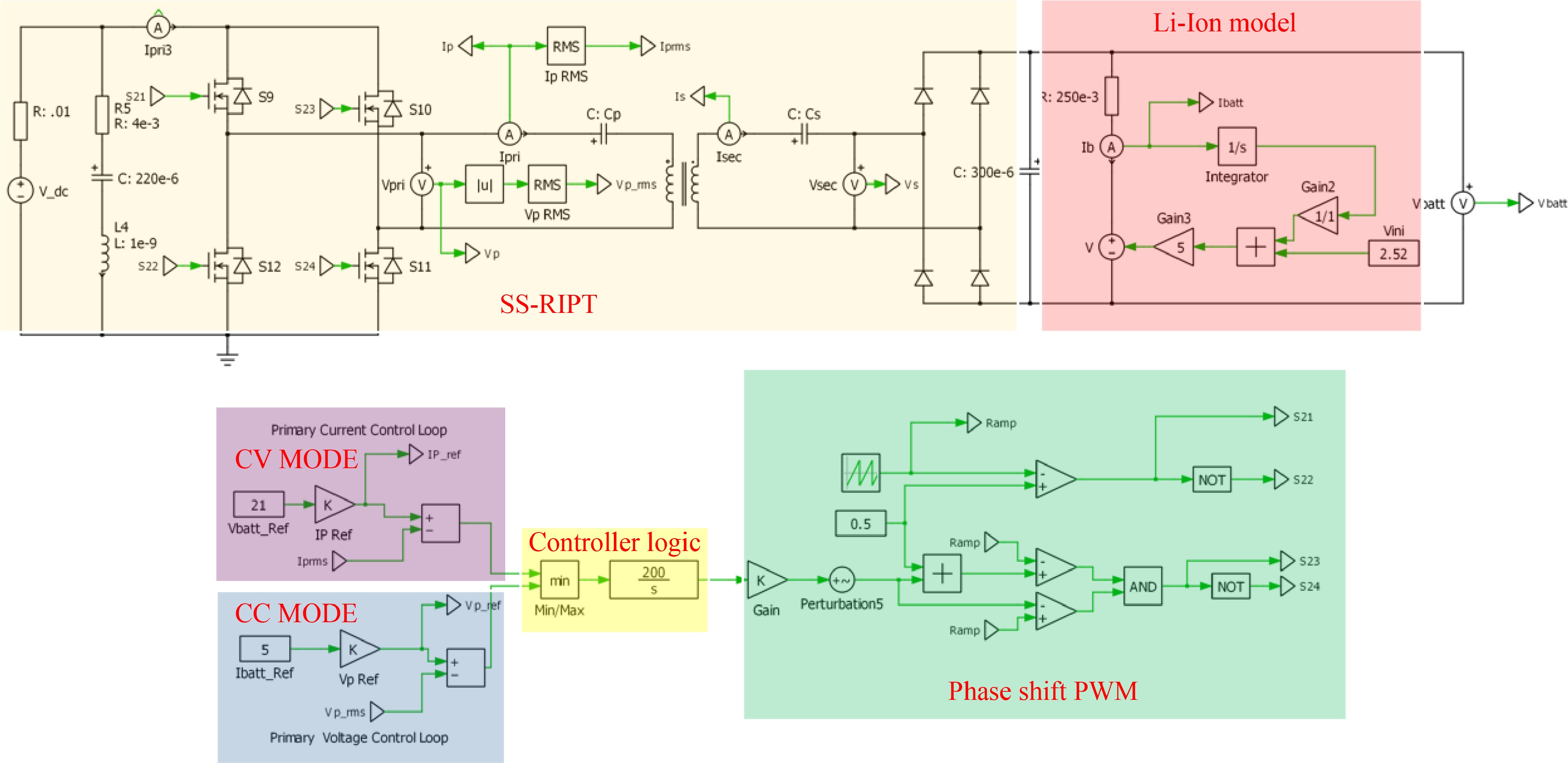
Figure 12.
PLECS simulation circuit of primary side indirect control of an Li-Ion charger using CC-CV charging.
-

Figure 13.
Simulation result for voltage controller: (a) step change in IBattREF from 5 to 3 A to change the VPREF, (b) primary side voltage and current waveform for the same.
-

Figure 14.
Simulation result for voltage controller: (a) change in load from 4.2 to 2 to 5 Ω, (b) primary side voltage and current waveform for the same.
-

Figure 15.
Simulation result for current controller: (a) step change in VBattREF from 21 to 12 V to change the IPREF, (b) primary side voltage and current waveform for the same.
-

Figure 16.
Simulation result for current controller: (a) change in load from 4.2 to 2 to 5 Ω, (b) Primary side voltage and current waveform for the same.
-

Figure 17.
CC-CV charging profile.
-

Figure 18.
Simulation result for voltage controller: (a) step change in VBattREF from 21 to 10 to 18 V, (b) primary side voltage and current waveform for the same.
-

Figure 19.
Simulation result for voltage controller: (a) change in load from 4.2 to 8 Ω, (b) primary side voltage and current waveform for the same.
-

Figure 20.
Simulation result for voltage controller: (a) step change in IBattREF from 5 to 2 to 4 A, (b) primary side voltage and current waveform for the same.
-

Figure 21.
Simulation result for current controller: (a) change in load from 4.2 to 3 Ω, (b) primary side voltage and current waveform for the same.
-

Figure 22.
CC-CV charging profile.
-
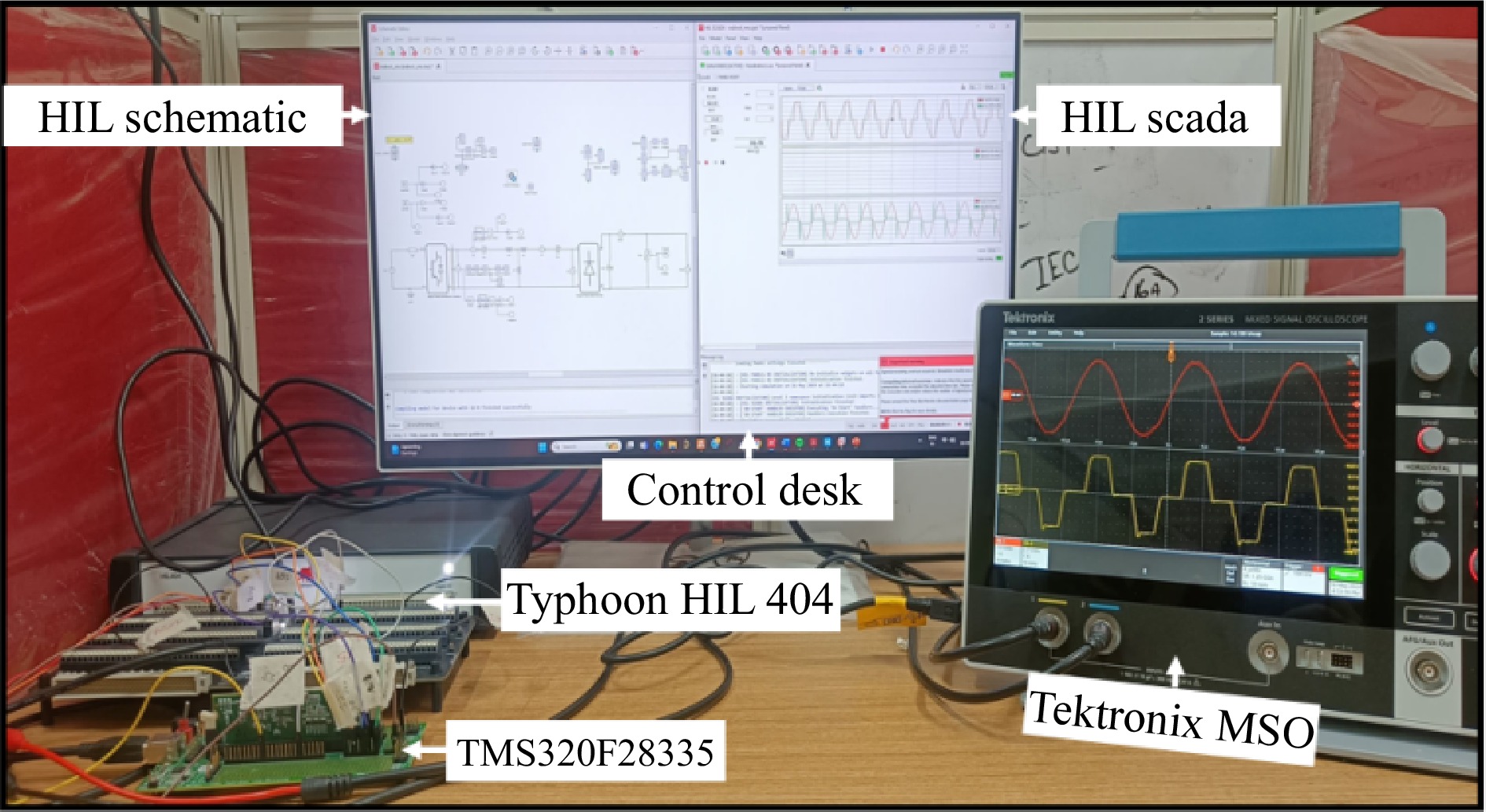
Figure 23.
Hardware in loop setup.
-
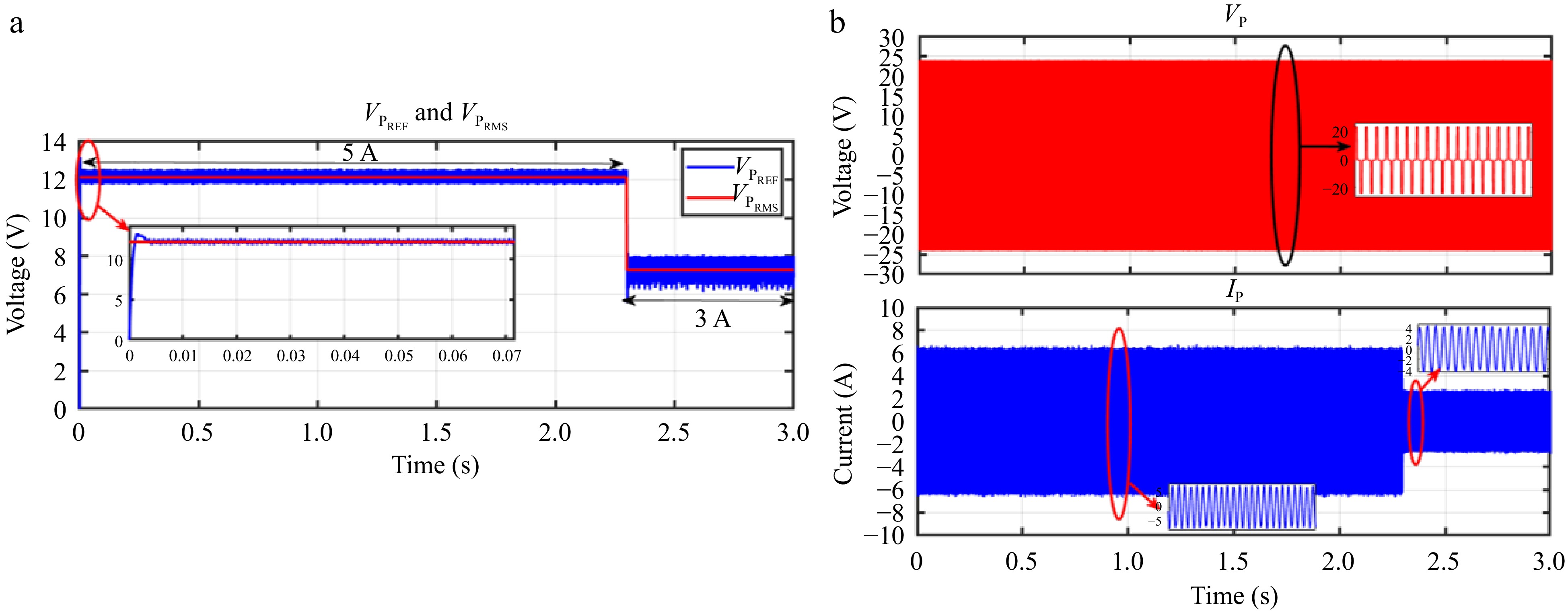
Figure 24.
HIL result for voltage controller: (a) step change in IBattREF from 5 to 3 A to change the VPREF, (b) primary side voltage and current waveform for the same.
-
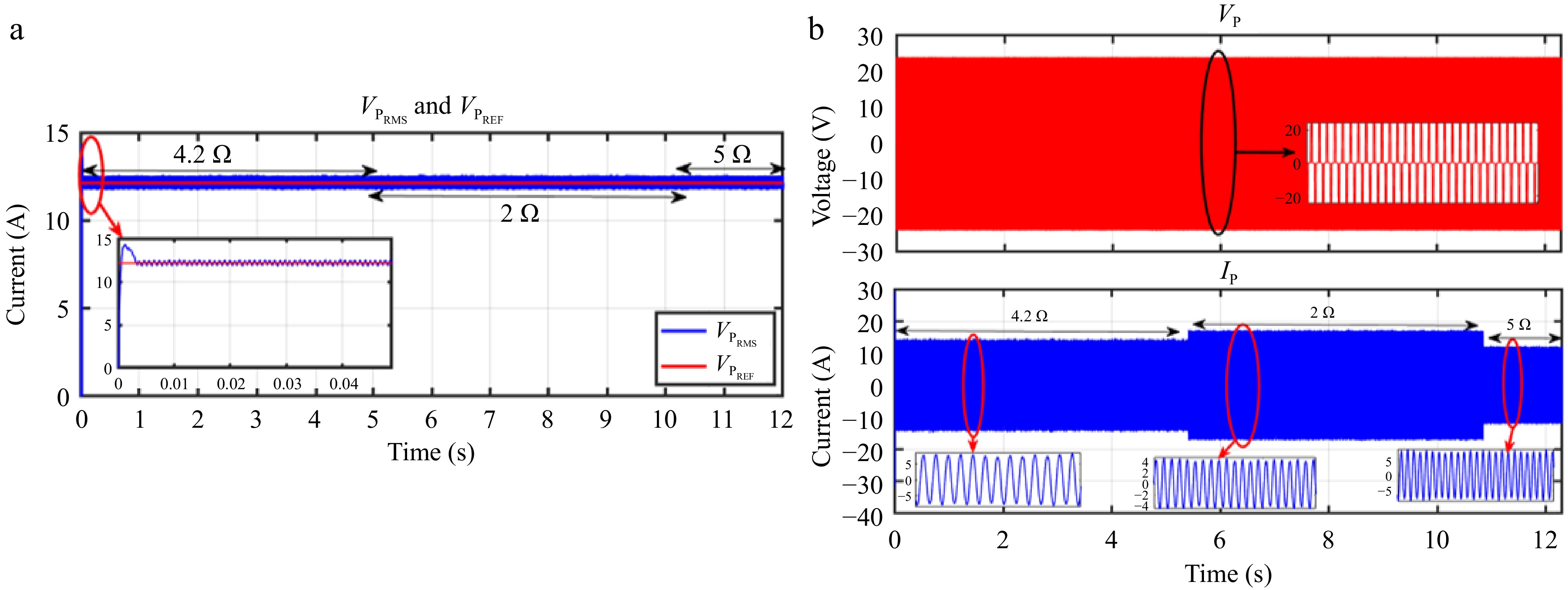
Figure 25.
HIL result for voltage controller: (a) change in load from 4.2 to 2 to 5 Ω, (b) primary side voltage and current waveform for the same.
-
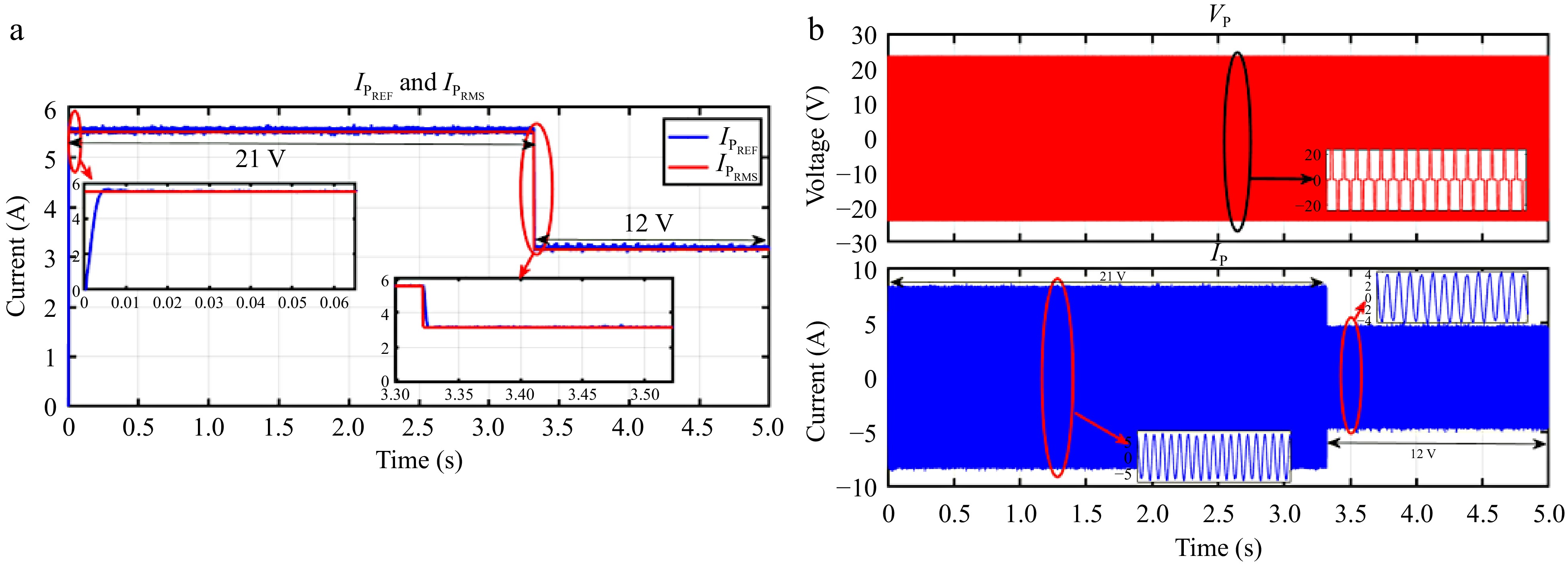
Figure 26.
HIL result for current controller: (a) step change in VBattREF from 21 to 12 V to change the IPREF, (b) primary side voltage and current waveform for the same.
-
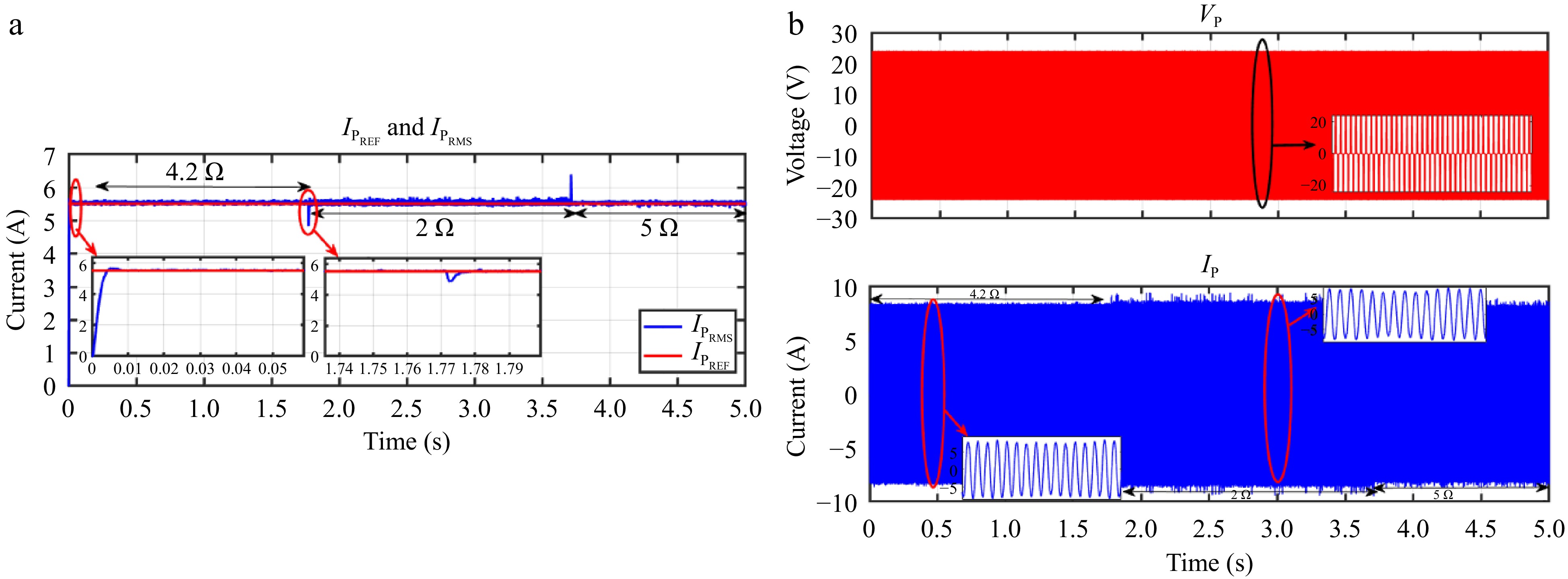
Figure 27.
HIL result for current controller: a) change in load from 4.2 to 2 to 5 Ω, (b) primary side voltage and current waveform for the same.
-

Figure 28.
HIL result for voltage controller: (a) step change in VBattREF from 21 to 10 to 18 V, (b) primary side voltage and current waveform for the same.
-

Figure 29.
HIL result for voltage controller: (a) change in load from 4.2 to 3 to 8 Ω, (b) primary side voltage and current waveform for the same.
-

Figure 30.
HIL result for voltage controller: (a) step change in IBattREF from 5 to 2 to 4 A, (b) primary side voltage and current waveform for the same.
-

Figure 31.
HIL result for current controller: (a) change in load from 4.2 to 2 to 3 Ω, (b) primary side voltage and current waveform for the same.
-
Type of control Control variables Direct control Primary side, direct control VBatt, IBatt Secondary side, direct control VBatt, IBatt Indirect control Primary side, indirect control (VP, IP) or (VS, IS) Secondary side, indirect control (VP, IP) or (VS, IS) Table 1.
Classification of control method for SS-RIPT systems.
-
Control strategy Advantages Limitations Primary side
direct controlIt is a straightforward and easy-to-implement control method. The direct use of battery current and voltage as feedback signals for the CC-CV controller simplifies the process of sensing DC variables. This approach reduces the weight and complexity on the receiver side. • The dependence on wireless communication modules for information transmission incurs additional expenses associated with both hardware and software requirements
• The transmitted information is vulnerable to errors, delays, and potential loss.
• Strong magnetic field interference may cause instability in the communication process.Primary side indirect control • It eliminates the need for a dedicated communication module, thereby eliminating the risk of information loss.
• The absence of a wireless communication module reduces the overall system cost.• Sensing primary side current and voltage at high frequencies, such as 100 kHz, is difficult due to the lack of readily available sensors with sufficient bandwidth.
• Indirect control strategies estimate battery current and voltage through mathematical equations rather than direct measurement, which may lead to slight discrepancies between the estimated and actual values.Secondary side direct control • It provides precise and robust performance without the need for communication between the receiver and transmitter.
• This approach facilitates the development of control systems aimed at enhancing efficiency and optimizing power charging.• This control approach results in increased weight and complexity on the receiver side. Secondary side indirect control • It does not require a dedicated communication module, thereby reducing the risk of information loss. • Sensing secondary side current and voltage at high frequencies, such as
100 kHz, is difficult due to the lack of readily available sensors with sufficient bandwidth.
• Indirect control strategies estimate battery current and voltage through mathematical equations rather than direct measurement, which may lead
to slight discrepancies between the estimated and actual values.Table 2.
Comparison between direct and indirect control.
-
Parameters Values Input voltage, Vdc 24 V CV mode voltage, Vbatt,max 4.2 × 5 = 21 V CC mode current, Ibatt 5 A Minimum output voltage, VBatt,min 0.6 × 21 = 12.6 V Maximum output power, Pout 21 × 5 = 105 W Switching frequency, fsw 85 kHz Table 3.
Specification of the SS-RIPT-based charger.
-
Parameters Values Primary inductance, LP 33.30 μH Secondary inductance, LS 39.73 μH Primary capacitance for 85 kHz, CP 105.27 nF Secondary capacitance for 85 kHz, CS 88.23 nF Mutual coupling 0.20 Table 4.
Parameters of the SS-RIPT link.
Figures
(31)
Tables
(4)