REVIEW   Open Access    

Perspectives on control strategies for CC-CV charging in Resonant Inductive Power Transfer systems: a review of SS-RIPT configuration

More Information
  • This paper explores control strategies for Resonant Inductive Power Transfer (RIPT) systems, focusing on achieving Constant Current Constant Voltage (CC-CV) charging for batteries. Wireless power transfer, particularly via RIPT, is gaining traction for charging Electric Vehicles (EVs), Unmanned Aerial Vehicles (UAVs), and consumer electronics. The study investigates direct and indirect control methods for RIPT systems, concentrating on the series-series RIPT (SS-RIPT) configuration. Through simulations and analysis, the paper showcases the implementation of primary side indirect control for CC-CV charging of Li-Ion batteries, offering insights into its feasibility and effectiveness. The findings contribute to advancing the understanding of control strategies in RIPT systems, facilitating the optimization of charging efficiency and enhancing user experience in wireless charging applications.
  • The Lonicera Linn. genus is a constituent member of the Caprifoliaceae family[1]. It is the largest genus in this family and comprises at least 200 species with a notable presence in North Africa, North America, Asia, and Europe[1]. Members of the Lonicera genus possess a wide range of economic benefits from their use as ornamental plants to food and as plants credited with numerous health benefits. Conspicuous among the numerous members of this genus with known medicinal uses are L. japonica, L. macranthoides, L. hypoglauca, L. confusa, and L. fulvotomentosa[2]. Though these species feature prominently in the Chinese Pharmacopoeia, other species such as L. acuminata, L. buchananii, and L. similis are recognized as medicinal resources in certain parts of China[1]. Among the aforementioned species, L. japonica takes precedence over the rest due to its high medicinal and nutritional value[3,4]. For instance, the microRNA MIR2911, an isolate from L. japonica, has been reported to inhibit the replication of viruses[57]. Also, the water extract of L. japonica has been used to produce various beverages and health products[8]. The Lonicera genus therefore possesses huge prospects in the pharmaceutical, food, and cosmetic industries as an invaluable raw material[9].

    The main active constituents of the Lonicera genus include organic acids, flavonoids, iridoids, and triterpene saponins. Chlorogenic acids, iridoids, and flavones are mainly credited with the anti-inflammatory, antiviral, anticancer, and antioxidant effects of the various Lonicera species[1013]. Their hepatoprotective, immune modulatory, anti-tumor and anti-Alzheimer’s effects are for the most part ascribed to the triterpene saponins[1416]. As stated in the Chinese Pharmacopoeia and backed by the findings of diverse research groups, the plants of the Lonicera genus are known to possess high amounts of organic acids (specifically chlorogenic acid) and pentacyclic triterpenoid saponins[2,1719]. The flower and flower bud have traditionally served as the main medicinal parts of the Lonicera genus even though there is ample evidence that the leaves possess the same chemical composition[20]. A perusal of the current scientific literature reveals the fact that little attention has been devoted to exploring the biosynthesis of the chemical constituents of the Lonicera genus with the view to finding alternative means of obtaining higher yields. It is therefore imperative that priority is given to the exploration of the biosynthesis of these bioactive compounds as a possible means of resource protection. There is also the need for further research on ways to fully tap the medicinal benefits of other plant parts in the Lonicera genus.

    Here, we provide a comprehensive review of relevant scientific literature covering the structure, pharmacology, multi-omics analyses, phylogenetic analysis, biosynthesis, and metabolic engineering of the main bioactive constituents of the Lonicera genus. Finally, we proffer suggestions on the prospects of fully exploiting and utilizing plants of the Lonicera genus as useful medicinal plant resources.

    A total of at least 400 secondary metabolites have been reported for the Lonicera genus. These metabolites are categorized into four main groups (Fig. 1a), including not less than 50 organic acids, 80 flavonoids, 80 iridoids, and 80 triterpene saponins[2123]. Organic acids are mainly derivatives of p-hydroxycinnamic acid and quinic acid. Among the organic acids, chlorogenic acids are reported to be the main bioactive compounds in L. japonica[2426]. The organic acids are most abundant in the leaves, while the least amounts are found in the stem of L. japonica. The flowers of the plant are known to contain moderately high amounts of organic acids[27]. The basic core structure of the flavonoids is 2-phenylchromogen. Luteolin and its glycoside which are characteristic flavonoids of the Lonicera genus are most abundant in L. japonica[28]. On the whole, the flavonoid contents in L. japonica are also highest in the leaves, available in moderate amounts in the flowers, and in lowest amounts in the stem[21]. The core structures of the iridoids are iridoid alcohols, the chemical properties of which are similar to hemiacetal. The iridoids often exist in the form of iridoid glycosides in plants. Secoiridoids glycosides are predominant in the Lonicera genus[25]. In L. japonica, the contents of the iridoids are most abundant in the flowers, moderate in leaves, and lowest in the stem[21]. The characteristic saponins of the Lonicera genus are mainly pentacyclic triterpenoids, including the hederin-, oleanane-, lupane-, ursulane- and fernane-types, etc[22]. The hederin-type saponins are reported in the highest amounts in L. macranthoides[17] (Fig. 1b).

    Figure 1.  Core structures of main secondary metabolites and their distribution in five species of Lonicera. (a) 1 and 2, the main core structures of organic acids; 3, the main core structures of flavonoids; 4, the main core structures of iridoids; 5, the main core structures of triterpene saponins. (b) Comparison of dry weight of four kinds of substances in five species of Lonicera[17,28].

    The similarities between chlorogenic acid (CGA) and flavonoids can be traced back to their biosynthesis since p-coumaroyl CoA serves as the common precursor for these compounds[29]. p-coumaroyl CoA is obtained through sequential catalysis of phenylalanine and its biosynthetic intermediates by phenylalanine-ammonia-lyase (PAL), cinnamate 4-hydroxylase (C4H) and 4-coumarate CoA ligase (4CL)[3033].

    CGA is a phenolic acid composed of caffeic acid and quinic acid and is the most important bioactive compound among the organic acids. Its biosynthesis has been relatively well-established; three main biosynthetic routes have been propounded (Fig. 2a). One route relates to the catalysis of caffeoyl-CoA and quinic acid by hydroxycinnamoyl-CoA quinate transferase (HQT)/hydroxycinnamoyl CoA shikimate/quinate hydroxycinnamoyl transferase (HCT) to produce CGA[3437]. The HQT-mediated pathway has been deemed the major route for CGA synthesis in in different plant species[38,39]. The second biosynthetic route stems from the biosynthesis of p-coumaroyl quinate through the catalytic effect of HCT/HQT and subsequent hydroxylation of p-coumaroyl quinate under the catalysis of p-coumarate 3'-hydroxylase (C3’H)[34,36,37]. For the third route, caffeoyl glucoside serves as the intermediate to form CGA, a process that is catalyzed by hydroxycinnamyl D-glucose: quinic acid hydroxycinnamyl transferase (HCGQT)[40,41].

    Figure 2.  Biosynthetic pathways of main bioactive constituents of Lonicera. (a) Biosynthetic pathways of chlorogenic acid. (b) Biosynthetic pathways of luteoloside. (c) Biosynthetic pathways of secologanin. (d) Biosynthetic pathways of hederin-type triterpene saponins. PAL, phenylalanine ammonia-lyase; C4H, cinnamate 4-hydroxylase; 4CL, 4-hydroxycinnamoyl CoA ligase; HCT, hydroxycinnamoyl CoA shikimate/quinate hydroxycinnamoyl transferase; C3’H, p-coumaroyl 3-hydroxylase; HQT, hydroxycinnamoyl-CoA quinate transferase; UGCT, UDP glucose: cinnamate glucosyl transferase; CGH, p-coumaroyl-D-glucose hydroxylase; HCGQT, hydroxycinnamoyl D-glucose: quinate hydroxycinnamoyl transferase; CHS, Chalcone synthase; CHI, Chalcone isomerase; FNS, Flavone synthase; F3H, flavonoid 30-monooxygenase/flavonoid 30-hydroxylase; UF7GT, flavone 7-O-β-glucosyltransferase; GPS, Geranyl pyrophosphatase; GES, geraniol synthase; G8O, geraniol 10-hydroxylase/8-oxidase; 8HO, 8-hydroxygeraniol oxidoreductase; IS, iridoid synthase; IO, iridoid oxidase; 7DLGT, 7-deoxyloganetic acid glucosyltransferase; 7DLH, 7-deoxyloganic acid hydroxylase; LAMT, loganic acid O-methyltransferase; SLS, secologanin synthase; FPS, farnesyl pyrophosphate synthase; SS, squalene synthase; SE, squalene epoxidase; β-AS, β-amyrin synthase; OAS, oleanolic acid synthetase.

    The key enzymes in the biosynthesis of p-coumaroyl CoA, and invariably CGA, thus, PAL, C4H, and 4CL have been established in diverse studies such as enzyme gene overexpression/knockdown[42], enzyme activity analysis[33] and transcriptomics[18]. However, the centrality of HQT in the biosynthesis of CGA remains disputable. While some studies have reported a strong correlation between HQT expression level with CGA content and distribution[18,35,39,43,44], others found no such link[45], bringing into question the role of HQT as a key enzyme in CGA biosynthesis.

    Few studies have been conducted on the regulation of CGA biosynthesis in the Lonicera genus. It was found that overexpression of the transcription factor, LmMYB15 in Nicotiana benthamiana can promote CGA accumulation by directly activating 4CL or indirectly binding to MYB3 and MYB4 promoters[46]. LjbZIP8 can specifically bind to PAL2 and act as a transcriptional repressor to reduce PAL2 expression levels and CGA content[47]. Under NaCl stress, increased PAL expression promoted the accumulation of phenolic substances in leaves without oxidative damage, a condition that was conducive to the accumulation of the bioactive compounds in leaves[48].

    Luteolin and its derivative luteolin 7-O- glucoside (luteoloside) are representative flavonoids of the Lonicera genus. Similar to CGA, luteolin is biosynthesized from p-coumaroyl CoA but via a different route. The transition from p-coumaroyl CoA to luteolin is underpinned by sequential catalysis by chalcone synthetase (CHS), chalcone isomerase (CHI), flavonoid synthetase (FNS), and flavonoid 3'-monooxygenase/flavonoid 3'-hydroxylase (F3'H)[45,49,50] (Fig. 2b). Luteoloside is synthesized from luteolin by UDP glucose-flavonoid 7-O-β-glucosyltransferase (UF7GT)[51]. Similar to CGA biosynthesis, the key enzymes of luteolin synthesis include PAL, C4H, and 4CL in addition to FNS[33,45,52]. The content of luteoloside was found to be highly abundant in senescing leaves relative to other tissues such as stem, flowers, and even young leaves[52]. Through transcriptomic analysis, luteoloside biosynthesis-related differentially expressed unigenes (DEGs) such as PAL2, C4H2, flavone 7-O-β-glucosyltransferase (UFGT), 4CL, C4H, chalcone synthase 2 and flavonoid 3'-monooxygenase (F3'H) genes were found to be upregulated in the senescing leaves. Biosynthesis-related transcription factors such as MYB, bHLH, and WD40 were also differentially expressed during leaf senescence[52], while bHLH, ERF, MYB, bZIP, and NAC were differentially expressed during flower growth[53]. Further analysis of the transcription factors revealed that MYB12, MYB44, MYB75, MYB114, MYC12, bHLH113, and TTG1 are crucial in luteoloside biosynthesis[52,53].

    The biosynthesis of terpenoids mainly involves three stages; formation of intermediates, formation of basic structural skeleton, and modification of basic skeleton[54]. The intermediates of terpenoids are mainly formed through the mevalonate (MVA) and methylerythritol phosphate (MEP) pathways, and eventually converted to the universal isoprenoid precursors, isopentenyl pyrophosphate (IPP) and its isomer dimethylallyl pyrophosphate (DMAPP) through a series of enzyme-catalyzed reactions. Under the catalysis of geranyl pyrophosphatase (GPS), IPP is then converted to geranyl pyrophosphate (GPP). Different terpenoids are subsequently derived from GPP as the intermediate product. For instance, in the formation of secoiridoid, GPP first removes the phosphoric acid group to obtain geraniol, second through a series of reactions such as oxidation and cyclization, the skeleton of iridoid, namely iridodial, can be obtained. Finally, through a series of reactions, the basic carbon skeleton of the secoiridoid, namely secologanin, is obtained[5561] (Fig. 2c). In the formation of triterpene saponins, the key step lies in the formation of the precursor, 2,3-oxidosqualene, a reaction that is catalyzed by squalene epoxidase (SE). There are many pentacyclic triterpenes in the Lonicera genus, the most important type being the hederin-type saponins with hederagenin as aglycones. Hederin-type saponins are produced after the synthesis of oleanolic acid from β-amyrin and catalyzed by β-starch synthetase (β-AS) and Oleanolic acid synthase (OAS)[62,63]. The skeletal modification of the triterpenoid saponins is mainly achieved via the activities of the CYP450 enzymes and UDP-glycosyltransferase (UGT). Hence, the corresponding aglycones are first obtained via oxidation by the CYP450 enzymes (e.g., CYP72A), and further subjected to glycosylation by the appropriate UGT enzyme[6365] (Fig. 2d). Skeletal formations of the iridoids and triterpene saponins in general have been well researched, but the same cannot be said about the enzymes involved in biosynthesis of these groups of compounds in the Lonicera genus. To fully utilize the iridoids and triterpene saponins in the Lonicera genus, it is necessary to further explore their biosyntheses with the view to enhancing and optimizing the process.

    Given the importance of the bioactive compounds in the Lonicera genus, continual isolation of these compounds using the traditional methods are not only tedious and time-consuming, but also unsustainable. With the development and application of microbial metabolic engineering, different strategies have been introduced to produce these bioactive compounds by heterologous synthesis (Table 1).

    Table 1.  Biosynthesis of Lonicera-specialized metabolites using metabolic engineering.
    Engineering bacteriaOperational methodsProductsYieldRefs
    S. cerevisiaeEliminate the tyrosine-induced feedback inhibition, delete genes involved in competing pathways and overexpress rate-limiting enzymesCaffeic acid569.0 mg/L[69]
    S. cerevisiaeEmploye a heterologous tyrosine ammonia lyase and a 4HPA3H complex composed of HpaB and HpaC derived from different speciesCaffeic acid289.4 mg/L[73]
    S. cerevisiaeSupply and recycle of three cofactors: FADH2, S-adenosyl-L-methion, NADPHCaffeic acid
    Ferulic acid
    Caffeic acid: 5.5 g/L;
    Ferulic acid: 3.8 g/L
    [117]
    E. coliKnocking out competing pathwaysCaffeic acid7,922 mg/L[118]
    E. coliArtificial microbial community, a polyculture of three recombinant Escherichia coli strainsChlorogenic acid250 μM[68]
    Cell-free biosynthesisExtract and purify spy-cyclized enzymes (CFBS-mixture)Chlorogenic acid711.26 mg/L[70]
    S. cerevisiaeThree metabolic engineering modules were systematically optimized: shikimate pathway and carbon distribution, branch pathways, CGA pathway genesChlorogenic acidFlask fermentation: 234.8 mg/L;
    Fed-batch fermentation:
    806.8 mg/L
    [119]
    E. coliUsing modular coculture engineering: construction of the defective strain improves the production and utilization of precursor substancesChlorogenic acid131.31 mg/L[122]
    E. coliIntroduce heterologous UDP-glucose biosynthetic genesLuteolin34 mg/L[120]
    Y. lipolyticaOverexpression of the key genes involved in the mevalonate pathway, the gene encoding cytochrome P450 (CYP716A12) to that encoding NADPH-P450 reductaseOleanolic acid129.9 mg/L[85]
    S. cerevisiaeImprove the pairing efficiency between Cytochrome P450 monooxygenase and reductase and the expression level of key genesOleanolic acid606.9 mg/L[121]
    S. cerevisiaeHeterologous expression and optimization of CrAS, CrAO, and AtCPR1, and regulation of ERG1 and NADPH regeneration systemOleanolic acid433.9 mg/L[123]
     | Show Table
    DownLoad: CSV

    Due to the demand for CGA in the food, pharmaceutical, chemical, and cosmetic industries, the traditional means of obtaining the same requires a relatively longer period for plant maturation to obtain low yields of the desired product. This therefore brings into question the sustainability and efficiency of this approach. The alternative and sustainable approach has been to produce CGA using synthetic biology and metabolic engineering.

    Current research has sought to utilize Escherichia coli (and its mutant strain) and Saccharomyces cerevisiae to synthetically generate CGA and other flavonoids[6673]. For instance, Cha et al. employed two strains of E. coli to produce a relatively good yield of CGA (78 mg/L). Their approach was based on the ability of one strain to generate caffeic acid from glucose and the other strain to use the caffeic acid produced and quinic acid as starting materials to synthesize CGA[66]. Using a bioengineered mutant of E. coli (aroD mutant), Kim et al. increased the yield of CGA to as high as 450 mg/L[67]. Others have sought to increase the yield of CGA by employing a polyculture of three E. coli strains that act as specific modules for the de novo biosynthesis of caffeic acid, quinic acid and CGA. This strategy eliminates the competition posed by the precursor of CGA (i.e., caffeic acid and quinic acid) and generally results in improved production of CGA[68]. Saccharomyces cerevisiae is a chassis widely used for the production of natural substances from plants with an intimal structure that can be used for the expression of cytochrome P450 enzymes that cannot be expressed in E. coli. Researchers have used yeast to increase the production of organic acids[69]. A de novo biosynthetic pathway for the construction of CGA in yeast has been reported new cell-free biosynthetic system based on a mixture of chassis cell extracts and purified Spy cyclized enzymes were adopted by Niu et al. to a produce the highest yield of CGA reported so far up to 711.26 ± 15.63 mg/L[70].

    There are many studies on the metabolic engineering for the synthesis of flavonoids, but few on luteolin and its glycosides. Strains of E. coli have been engineered with specific uridine diphosphate (UDP)-dependent glycosyltransferase (UGT) to synthesize three novel flavonoid glycosides. These glycosides were quercetin 3-O-(N-acetyl) quinovosamine (158.3 mg/L), luteolin 7-O-(N-acetyl) glucosaminuronic acid (172.5 mg/L) and quercetin 3-O-(N-acetyl)-xylosamine (160.8 mg/L)[71]. Since most of the flavonoid glycosides synthesized in E. coli are glucosylated, Kim et al. in their bid to synthesize luteolin-7-O-glucuronide, deleted the araA gene that encodes UDP-4-deoxy-4-formamido-L-arabinose formyltransferase/UDP-glucuronic acid C-4'' decarboxylase in E.coli and were able to obtain a yield of 300 mg/L of the desired product[72].

    Terpenoidal saponins are mostly derived from slow-growing plants and usually possess multiple chiral centers[74]. Traditional isolation and even chemical synthesis of the terpenoidal saponins are both tedious and uneconomical for large-scale production. Therefore, it is necessary to find other ways to synthesize these compounds known to have diverse pharmacological functions.

    Heterologous synthesis has become an important way to improve the target products. With the development of synthetic biology, heterologous synthesis of triterpene saponins involves chassis of both plant and microbial origin. In this regard, Nicotiana benthamiana is a model plant species for the reconstruction of the biosynthetic pathways of different bioactive compounds including monoterpenes, hemiterpenes, and diterpenes[59,7577]. Aside from Nicotiana benthamiana, other plants have also been used as heterologous hosts[78]. Heterologous synthesis using microbial hosts mainly involves Saccharomyces cerevisiae and Escherichia coli[7981], and other microorganisms[82,83]. Comparatively, plants as biosynthetic hosts have the advantages of an established photosynthetic system, abundant supply of relevant enzymes, and presence of cell compartments, etc. They are however not as fast growing as the microorganisms, and it is also difficult to extract and separate the desired synthesized compounds from them as hosts.

    Although heterologous synthesis has many advantages, the premise of successful construction of synthetic pathway in host is to elucidate the unique structure of the compound and the key enzyme reaction mechanism in the biosynthetic pathway. There is little research on metabolic engineering of the hederin-type pentacyclic triterpene saponins in Lonicera, but there are studies on the heterologous synthesis of its aglycone precursor, oleanolic acid[84,85]. There is a dearth of scientific literature on key enzymes in the biosynthesis of pentacyclic triterpenoid saponins in the Lonicera genus.

    Scientific evidence by diverse research groups has linked members of the Lonicera genus to a wide range of pharmacological effects (Fig. 3). These pharmacological effects are elicited by different chemical constituents, much of the underlying mechanisms of which have been elucidated by the omics techniques. Here, we summarize the pharmacological effects and pharmacodynamics of the Lonicera genus in the last 6 years.

    Figure 3.  Schematic summary of four main pharmacological effects (anti-inflammatory, antimicrobial, anti-oxidative and hepatoprotective effects) of the Lonicera genus and the underlying mechanisms of actions.

    Bioactive compounds of plants in the Lonicera genus have demonstrated varying degrees of anti-inflammatory actions. In a recent study, Lv et al. showed that lonicerin inhibits the activation of NOD-like receptor thermal protein domain associated protein 3 (NLRP3) through regulating EZH2/AtG5-mediated autophagy in bone marrow-derived macrophages of C57BL/6 mice[86]. The polysaccharide extract of L. japonica reduces atopic dermatitis in mice by promoting Nrf2 activation and NLRP3 degradation through p62[87]. Several products of Lonicera have been reported to have ameliorative effects on DSS-induced colitis. Among them, flavonoids of L. rupicola can improve the ulcerative colitis of C57BL/6 mice by inhibiting PI3K/AKT, and pomace of L. japonica can improve the ulcerative colitis of C57BL/6 mice by improving the intestinal barrier and intestinal flora[88,89]. The flavonoids can also ameliorate ulcerative colitis induced by local enema of 2,4,6-trinitrobenzene sulfonic acid (TNBS) in Wistar rats by inhibiting NF-κB pathway[90]. Ethanol extract from L. Japonica has demonstrated the potential to inhibit the expressions of inflammatory cytokines in serum and macrophages of LPS-induced ICR mice[91]. The water extract of L. japonica and luteolin were found to exhibit their anti-inflammatory effects via the inhibition of the JAK/STAT1/3-dependent NF-κB pathway and induction of HO-1 expression in RAW263.7 cells induced by pseudorabies virus (PRV)[92].

    Existing scientific evidence indicates that the extracts of plants in the Lonicera genus exhibit strong inhibition against different pathogenic microorganisms. Phenolic compounds from L. japonica demonstrated a particularly significant inhibitory effect against Staphylococcus aureus and Escherichia coli, in vitro, making these compounds potential food preservatives[93]. Influenza A virus is a serious threat to human health. Recent research has found the ethanol extract of L. japonica to possess a strong inhibitory effect against H1N1 influenza virus-infected MDCK cells and ICR mice[94]. The incidence of the COVID-19 pandemic called to action various scientists in a bid to find safe and efficacious treatment[95]. Traditional Chinese medicines became an attractive alternative in this search. The water extract of the flower bud of L. japonica which has traditionally served as a good antipyretic and antitussive agent attracted the attention of researchers. Scientific evidences have confirmed that the water extract of L. japonica can induce let-7a expression in human rhabdomyosarcoma cells or neuronal cells and blood of lactating mice, inhibiting the entry and replication of the virus in vitro and in vivo[96]. In addition, the water extract of L. japonica also inhibits the fusion of human lung cancer cells Calu-3 expressing ACE2 receptor and BGK-21 cells transfected with SARS-CoV-2 spike protein, and up-regulates the expression of miR-148b and miR-146a[97].

    Oxidative stress has been implicated in the pathophysiology of many diseases, hence, amelioration of the same could be a good therapeutic approach[98,99]. In keeping with this therapeutic strategy, various compounds from the Lonicera genus have demonstrated the ability to relieve oxidative stress due to their pronounced antioxidant effects. For instance, the polyphenolic extract of L. caerulea berry was found to activate the expression of AMPK-PGC1α-NRF1-TFAM proteins in the skeletal muscle mitochondria, improve the activity of SOD, CAT and GSH-Px enzymes in blood and skeletal muscle, relieve exercise fatigue in mice by reducing oxidative stress in skeletal muscle, and enhance mitochondrial biosynthesis and cell proliferation[100]. The diverse health benefits of the anthocyanins from L. japonica have been mainly credited to their antioxidant and anti-inflammatory effects. The anthocyanin and cyanidin-3-o-glucoside have been reported to possess the potential to prolong life and delay senescence of Drosophila through the activation of the KEAP1/NRF2 signaling pathway[101].

    The liver is an essential organ that contributes to food digestion and detoxification of the body. These functions expose the liver to diverse toxins and metabolites. The Lonicera genus is rich in phytochemicals that confer protection on the liver against various toxins. The phenolic compound, 4, 5-di-O-Caffeoylquinic acid methyl ester was shown to be able to improve H2O2-induced liver oxidative damage in HepG2 cells by targeting the Keap1/Nrf2 pathway[102]. Hepatic fibrosis is a complex dynamic process, with the propensity to progress to liver cancer in severe cases. The L. japonicae flos water extract solution increased the cell viability of FL83B cells treated with thioacetamide (TAA), decreased the levels of serum alanine aminotransferase (ALT) and alkaline phosphatase (ALP), inhibited the transformation growth factor β1 (TGF-β1) and liver collagen deposition[103]. Sweroside, a secoiridoid glucoside isolate of L. japonica is known to protect the C57BL/6 mice liver from hepatic fibrosis by up-regulating miR-29a and inhibiting COL1 and TIMP1[104].

    Aside from the aforementioned, other pharmacological effects have been ascribed to the Lonicera genus. The ethanolic extract of L. caerulea has been reported to inhibit the proliferation of SMMC-7721 and H22 hepatoma cells, while its anthocyanins induced the apoptosis of tumor cells via the release of cytochrome C and activation of caspase[105]. AMPK/PPARα axes play an important role in lipid metabolism. A chlorogenic acid-rich extract of L. Japonica was found to significantly decrease the early onset of high-fat diet-induced diabetes in Sprague-Dawley rats via the CTRPs-AdipoRs-AMPK/PPARα axes[106]. In a high-fat diet-induced non-alcoholic fatty liver disease in C57BL/6 mice, treatment with L. caerulea polyphenol extract decreased serum inflammatory factors and endotoxin levels and the Firmicutes/Bacteroidetes ratio, an indication of its modulatory effect on the gut microbiota[107]. The iridoid-anthocyanin extract from L. caerulea berry contributed to alleviating the symptoms of intestinal infection with spirochaeta in mice[108].

    The traditional classification of the Lonicera genus based on the morphology of member plants is further categorized into two subgenera, Chamaecerasus and Periclymenum. The Chamaecerasus includes four categories, Coeloxylosteum, Isika, Isoxylosteum and Nintooa. The Periclymenum includes two categories, Subsect. Lonicera and Subsect. Phenianthi (Supplemental Table S1).

    High-throughput chloroplast genome sequencing of L. japonica found its length to be 155078 bp, which is similar to the structure of the typical angiosperm chloroplast genome. It contains a pair of inverted repeat regions (IRa and IRb, 23774 bp), a large single copy region (LSC, 88858 bp) and a small single copy area (SSC, 18672 bp)[109,110]. However, compared with chloroplast genomes of other plants, the chloroplast genome of L. japonica has a unique rearrangement between trnI-CAU and trnN-GUU[110]. Based on the phylogenetic analysis of the plastid genomes of seven plants in the Lonicera genus, 16 diverging hot spots were identified as potential molecular markers for the development of the Lonicera plants[111]. The phylogeny of Lonicera is rarely researched at the molecular level and the pattern of repetitive variation and adaptive evolution of the genome sequence is still unknown. Chloroplast genome sequences are highly conserved, but insertions and deletions, inversions, substitutions, genome rearrangements, and translocations also occur and have become powerful tools for studying plant phylogeny[112,113].

    We present here the phylogenetic tree of the Lonicera genus based on the published complete chloroplast genome sequences downloaded from the National Center for Biotechnology Information (NCBI) database using the Maximum likelihood method (Fig. 4). Based on our chloroplast phylogenies, we propose to merge L. harae into Sect. Isika and L. insularis into Chamaecerasus, but whether L. insularis belongs to Sect. Isika or Sect. Coeloxylosteum is uncertain. Based on protein-coding regions (CDS) of the chloroplast genome or complete chloroplast genomes, Liu et al. and Chen et al. supported the classification of the two subgenera in Lonicera[111,114]. Sun et al. and Srivastav et al. demonstrated a classification between the two subgenera with more species by using sequences of nuclear loci generated, chloroplast genome, and restriction site-associated DNA sequencing (RADSeq)[115,116]. However, our phylogenetic analysis and that of Sun et al. show relations within the subgenus Chamaecerasus are tanglesome in some respects[116]. Plant traits are affected by the environment to varying degrees. Since evidence of plant speciation is implicit in its genome sequence, comparative analysis at the molecular level provides a relatively accurate depiction of inherent changes that might have occurred over time. These findings suggest the need for more species of the Lonicera genus to be sequenced to provide a more accurate theoretical basis for the evolution of the Lonicera plants and a more effective revision in the classification of the Lonicera genus.

    Figure 4.  Phylogenetic tree of 42 species of the Lonicera genus based on complete chloroplast genome sequence data. The phylogenetic tree was constructed by the maximum likelihood method. Coeloxylosteum, Isika, Isoxylosteum, and Nintooa belong to Chamaecerasus and Subsect. Lonicera belongs to the Periclymenum. Chamaecerasus and Periclymenum are the two subgenera of Lonicera. 'Not retrieved' indicates that the species failed to retrieve a subordinate taxon in the Lonicera.

    The Lonicera genus is rich in diverse bioactive compounds with immeasurable prospects in many fields. Members of this genus have been used for thousands of years in traditional Chinese medicine for heat-clearing and detoxification. These plants generally have a good taste and form part of the ingredients of various fruit juices. In cosmetics, they are known to possess anti-aging and moisturizing functions. Plants of the Lonicera genus are also known for their good ecological adaptability and can be used to improve soil and ecological environment. Based on the value of the Lonicera genus, besides researching their use through molecular biological means, their efficient utilization can also be promoted in the following ways: (1) The stems and leaves of the plants could be developed for consumption and use since the chemical profiles of these parts do not differ significantly from the flowers. This way, the wastage of this scarce resource could be minimized or avoided. (2) Most of the Lonicera plants are vines or shrubs and their natural regeneration speed is slow, so the introduction and domestication of species could be strengthened to avoid overexploitation of wild resources.

    At present, only the research on the biosynthesis and efficacy of chlorogenic acid is quite comprehensive and has been used widely in various fields. There is limited research on various aspects of other bioactive compounds and should therefore be given priority in future research goals. Currently, the multi-omics analytical approach has gradually evolved as a reliable and helpful analytical platform. Hence, multi-omics research on the Lonicera genus could lead to discoveries in drug discovery and human health.

    The authors confirm contribution to the paper as follows: study conception and design, draft manuscript preparation: Yin X, Chen X, Li W, Tran LSP, Lu X; manuscript revision: Yin X, Chen X, Li W, Tran LSP, Lu X, Chen X, Yin X, Alolga RN; data/literature collection: Chen X, Yin X; figure preparation: Chen X, Yin X; figure revision: Alolga RN, Yin X, Chen X, Li W, Tran LSP, Lu X. All authors reviewed the results and approved the final version of the manuscript.

    All data generated or analyzed during this study are included in this published article and its supplementary information file.

    This work was partially supported by the National Natural Science Foundation of China (NSFC, Nos 82173918 and 82373983).

  • The authors declare that they have no conflict of interest. Xiaojian Yin is the Editorial Board member of Medicinal Plant Biology who was blinded from reviewing or making decisions on the manuscript. The article was subject to the journal's standard procedures, with peer-review handled independently of this Editorial Board member and the research groups.

  • [1]

    Green AW, Boys JT. 1994.10 kHz inductively coupled power transfer - concept and control. Proceedings of 5 th International Conference on Power Electronics and Variable-Speed Drives, London, UK, 26−28 October 1994. USA: IEEE. pp. 694−99. doi: 10.1049/cp:19941049

    [2]

    Sikandar MS, Darwish M, Marouchos C. 2022. Review of wireless charging of EV. 2022 57th International Universities Power Engineering Conference (UPEC). Istanbul, Turkey, 30 August - 2 September 2022. USA: IEEE. pp. 1−4. doi: 10.1109/UPEC55022.2022.9917793

    [3]

    Lu M, Bagheri M, James AP, Phung T. 2018. Wireless charging techniques for UAVs: a review, reconceptualization, and extension. IEEE Access 6:29865−84

    doi: 10.1109/ACCESS.2018.2841376

    CrossRef   Google Scholar

    [4]

    Wang P, Kim J, Mutahira H, Muhammad MS. 2024. Autonomous drone control for wireless charging using power lines. 2024 18 th International Conference on Ubiquitous Information Management and Communication (IMCOM). Kuala Lumpur, Malaysia, 3−5 January 2024. USA: IEEE. pp. 1−8. doi: 10.1109/IMCOM60618.2024.10418347

    [5]

    Hannan MA, Lipu MSH, Hussain A, Mohamed A. 2017. A review of lithium-ion battery state of charge estimation and management system in electric vehicle applications: challenges and recommendations. Renewable and Sustainable Energy Reviews 78:834−54

    doi: 10.1016/j.rser.2017.05.001

    CrossRef   Google Scholar

    [6]

    Huang Z, Qin T, Li XL, Ding L, Iu HHC, et al. 2024. Synthesis of inductive power transfer converters with dual immittance networks for inherent CC-to-CV charging profiles. IEEE Transactions on Power Electronics 39:7766−77

    doi: 10.1109/TPEL.2024.3382112

    CrossRef   Google Scholar

    [7]

    Du Y, Zhang Z, Zuo Z, Wang Y. 2024. Lithium battery charging optimization via multi-stage combined charging strategy in solar-powered vehicles. Journal of Energy Storage 83:110716

    doi: 10.1016/j.est.2024.110716

    CrossRef   Google Scholar

    [8]

    Chen GJ, Liu CL, Liu YH, Wang JJ. 2024. Implementation of constant temperature–constant voltage charging method with energy loss minimization for lithium-ion batteries. Electronics 13:645

    doi: 10.3390/electronics13030645

    CrossRef   Google Scholar

    [9]

    Mahesh A, Chokkalingam B, Mihet-Popa L. 2021. Inductive wireless power transfer charging for electric vehicles – a review. IEEE Access 9:137667−713

    doi: 10.1109/ACCESS.2021.3116678

    CrossRef   Google Scholar

    [10]

    Covic GA, Boys JT. 2013. Inductive power transfer. Proceedings of the IEEE 101(6):1276−89

    doi: 10.1109/JPROC.2013.2244536

    CrossRef   Google Scholar

    [11]

    Liu J, Chan KW, Chung CY, Chan NHL, Liu M, et al. 2018. Single-stage wireless-power-transfer resonant converter with boost bridgeless power-factor-correction rectifier. IEEE Transactions on Industrial Electronics 65:2145−55

    doi: 10.1109/TIE.2017.2745471

    CrossRef   Google Scholar

    [12]

    Rodriguez JR, Dixon JW, Espinoza JR, Pontt J, Lezana P. 2005. PWM regenerative rectifiers: state of the art. IEEE Transactions on Industrial Electronics 52:5−22

    doi: 10.1109/TIE.2004.841149

    CrossRef   Google Scholar

    [13]

    Peschiera B, Aditya K, Williamson SS. 2014. Asymmetrical voltage-cancellation control for a series-series fixed-frequency inductive power transfer system. IECON 2014 - 40 th Annual Conference of the IEEE Industrial Electronics Society. Dallas, TX, USA, 29 October - 1 November 2014. USA: IEEE. pp. 2971−77. doi: 10.1109/IECON.2014.7048932

    [14]

    Kavimandan UD, Mahajan SM, Van Neste CW. 2021. Analysis and demonstration of a dynamic ZVS angle control using a tuning capacitor in a wireless power transfer system. IEEE Journal of Emerging and Selected Topics in Power Electronics 9:1876−90

    doi: 10.1109/JESTPE.2020.2997822

    CrossRef   Google Scholar

    [15]

    Miller JM, Onar OC, Chinthavali M. 2015. Primary-side power flow control of wireless power transfer for electric vehicle charging. IEEE Journal of Emerging and Selected Topics in Power Electronics 3:147−62

    doi: 10.1109/JESTPE.2014.2382569

    CrossRef   Google Scholar

    [16]

    Gati E, Kampitsis G, Manias S. 2017. Variable frequency controller for inductive power transfer in dynamic conditions. IEEE Transactions on Power Electronics 32:1684−96

    doi: 10.1109/TPEL.2016.2555963

    CrossRef   Google Scholar

    [17]

    Diekhans T, De Doncker RW. 2015. A dual-side controlled inductive power transfer system optimized for large coupling factor variations and partial load. IEEE Transactions on Power Electronics 30:6320−28

    doi: 10.1109/TPEL.2015.2393912

    CrossRef   Google Scholar

    [18]

    Madawala UK, Neath M, Thrimawithana DJ. 2013. A power–frequency controller for bidirectional inductive power transfer systems. IEEE Transactions on Industrial Electronics 60:310−17

    doi: 10.1109/tie.2011.2174537

    CrossRef   Google Scholar

    [19]

    Chow JPW, Chung HSH, Cheng CS. 2016. Use of transmitter-side electrical information to estimate mutual inductance and regulate receiver-side power in wireless inductive link. IEEE Transactions on Power Electronics 31:6079−91

    doi: 10.1109/TPEL.2016.2530816

    CrossRef   Google Scholar

    [20]

    Madawala UK, Thrimawithana DJ. 2012. New technique for inductive power transfer using a single controller. IET Power Electronics 5:248

    doi: 10.1049/iet-pel.2011.0121

    CrossRef   Google Scholar

    [21]

    Song K, Li Z, Jiang J, Zhu C. 2018. Constant current/voltage charging operation for series–series and series–parallel compensated wireless power transfer systems employing primary-side controller. IEEE Transactions on Power Electronics 33:8065−80

    doi: 10.1109/TPEL.2017.2767099

    CrossRef   Google Scholar

    [22]

    Li Z, Liu H, Tian Y, Liu Y. 2021. Constant current/voltage charging for primary-side controlled wireless charging system without using dual-side communication. IEEE Transactions on Power Electronics 36:13562−77

    doi: 10.1109/TPEL.2021.3088272

    CrossRef   Google Scholar

    [23]

    Zhang Y, Chen S, Li X, Tang Y. 2021. Dual-side phase-shift control of wireless power transfer implemented on primary side based on driving windings. IEEE Transactions on Industrial Electronics 68(9):8999−9002

    doi: 10.1109/TIE.2020.3013522

    CrossRef   Google Scholar

    [24]

    Jia S, Chen C, Duan S, Chao Z. 2021. Dual-side asymmetrical voltage-cancelation control for bidirectional inductive power transfer systems. IEEE Transactions on Industrial Electronics 68(9):8061−71

    doi: 10.1109/TIE.2020.3016265

    CrossRef   Google Scholar

    [25]

    Wu M, Yang X, Chen W, Wang L, Jiang Y, et al. 2021. A dual-sided control strategy based on mode switching for efficiency optimization in wireless power transfer system. IEEE Transactions on Power Electronics 36(8):8835−48

    doi: 10.1109/TPEL.2021.3055963

    CrossRef   Google Scholar

    [26]

    Thrimawithana DJ, Madawala UK. 2010. A primary side controller for inductive power transfer systems. 2010 IEEE International Conference on Industrial Technology. Via del Mar, Chile, 14−17 March 2010. USA: IEEE. pp. 661−66. doi: 10.1109/ICIT.2010.5472724

    [27]

    Wang C, Zhu C, Song K, Wei G, Dong S, et al. 2017. Primary-side control method in two-transmitter inductive wireless power transfer systems for dynamic wireless charging applications. 2017 IEEE PELS Workshop on Emerging Technologies: Wireless Power Transfer (WoW). Chongqing, China, 20−22 May 2017. USA: IEEE. pp. 1−6. doi: 10.1109/WoW.2017.7959366

    [28]

    Liu Y, Madawala UK, Mai R, He Z. 2021. Primary-side parameter estimation method for bidirectional inductive power transfer systems. IEEE Transactions on Power Electronics 36:68−72

    doi: 10.1109/TPEL.2020.3005404

    CrossRef   Google Scholar

    [29]

    Aditya K, Williamson SS. 2015. Advanced controller design for a series-series compensated inductive power transfer charging infrastructure using asymmetrical clamped mode control. 2015 IEEE Applied Power Electronics Conference and Exposition (APEC). Charlotte, NC, USA, 15−19 March 2015. USA: IEEE. pp. 2718−24. doi: 10.1109/APEC.2015.7104735

    [30]

    Lovison G, Imura T, Hori Y. 2016. Secondary-side-only simultaneous power and efficiency control by online mutual inductance estimation for dynamic wireless power transfer. IECON 2016 - 42nd Annual Conference of the IEEE Industrial Electronics Society. Florence, Italy, 23−26 October 2016. USA: IEEE. pp. 4553−58. doi: 10.1109/IECON.2016.7793790

    [31]

    Pang B, Deng J, Liu P, Wang Z. 2017. Secondary-side power control method for double-side LCC compensation topology in wireless EV charger application. IECON 2017 - 43 rd Annual Conference of the IEEE Industrial Electronics Society. Beijing, China, 29 October - 1 November 2017. USA: IEEE. pp. 7860−65. doi: 10.1109/IECON.2017.8217377

    [32]

    Hatchavanich N, Sangswang A, Konghirun M. 2020. Secondary-side voltage control via primary-side controller for wireless EV chargers. IEEE Access 8:203543−54

    doi: 10.1109/ACCESS.2020.3036542

    CrossRef   Google Scholar

    [33]

    Madawala UK, Neath M, Thrimawithana DJ. 2013. A power–frequency controller for bidirectional inductive power transfer systems. IEEE Transactions on Industrial Electronics 60(1):310−17

    doi: 10.1109/TIE.2011.2174537

    CrossRef   Google Scholar

    [34]

    Tang Y, Chen Y, Madawala UK, Thrimawithana DJ, Ma H. 2018. A new controller for bidirectional wireless power transfer systems. IEEE Transactions on Power Electronics 33(10):9076−87

    doi: 10.1109/TPEL.2017.2785365

    CrossRef   Google Scholar

    [35]

    Cai J, Sun P, Ji K, Wu X, Ji H, et al. 2024. Constant-voltage and constant-current controls of the inductive power transfer system for electric vehicles based on full-bridge synchronous rectification. Electronics 13(9):1686

    doi: 10.3390/electronics13091686

    CrossRef   Google Scholar

    [36]

    Shipra K, Maurya R. 2024. Brayton-Moser passivity-based controller for an on-board integrated electric vehicle battery charger. Journal of Energy Storage 75:109652

    doi: 10.1016/j.est.2023.109652

    CrossRef   Google Scholar

    [37]

    Aditya K. 2023. Sizing wireless battery charger for the CC-CV charging of lithium polymer battery used in unmanned aerial vehicle. 2023 IEEE 3rd International Conference on Sustainable Energy and Future Electric Transportation (SEFET). Bhubaneswar, India, 9-12 August 2023. USA: IEEE. pp. 1−6. doi: 10.1109/SeFeT57834.2023.10245551

    [38]

    Pradhan S, Munsi A, Aditya K. 2023. Ensuring safe and reliable wireless charging of unmanned aerial vehicles: the imperative for foreign object detection methods. 2023 IEEE 3 rd International Conference on Sustainable Energy and Future Electric Transportation (SEFET). Bhubaneswar, India, 9−12 August 2023. USA: IEEE. pp. 1−6. doi: 10.1109/SeFeT57834.2023.10245524

  • Cite this article

    Munsi A, Pradhan S, Aditya K. 2024. Perspectives on control strategies for CC-CV charging in Resonant Inductive Power Transfer systems: a review of SS-RIPT configuration. Wireless Power Transfer 11: e009 doi: 10.48130/wpt-0024-0009
    Munsi A, Pradhan S, Aditya K. 2024. Perspectives on control strategies for CC-CV charging in Resonant Inductive Power Transfer systems: a review of SS-RIPT configuration. Wireless Power Transfer 11: e009 doi: 10.48130/wpt-0024-0009

Figures(31)  /  Tables(4)

Article Metrics

Article views(1667) PDF downloads(383)

Other Articles By Authors

REVIEW   Open Access    

Perspectives on control strategies for CC-CV charging in Resonant Inductive Power Transfer systems: a review of SS-RIPT configuration

Wireless Power Transfer  11 Article number: e009  (2024)  |  Cite this article

Abstract: This paper explores control strategies for Resonant Inductive Power Transfer (RIPT) systems, focusing on achieving Constant Current Constant Voltage (CC-CV) charging for batteries. Wireless power transfer, particularly via RIPT, is gaining traction for charging Electric Vehicles (EVs), Unmanned Aerial Vehicles (UAVs), and consumer electronics. The study investigates direct and indirect control methods for RIPT systems, concentrating on the series-series RIPT (SS-RIPT) configuration. Through simulations and analysis, the paper showcases the implementation of primary side indirect control for CC-CV charging of Li-Ion batteries, offering insights into its feasibility and effectiveness. The findings contribute to advancing the understanding of control strategies in RIPT systems, facilitating the optimization of charging efficiency and enhancing user experience in wireless charging applications.

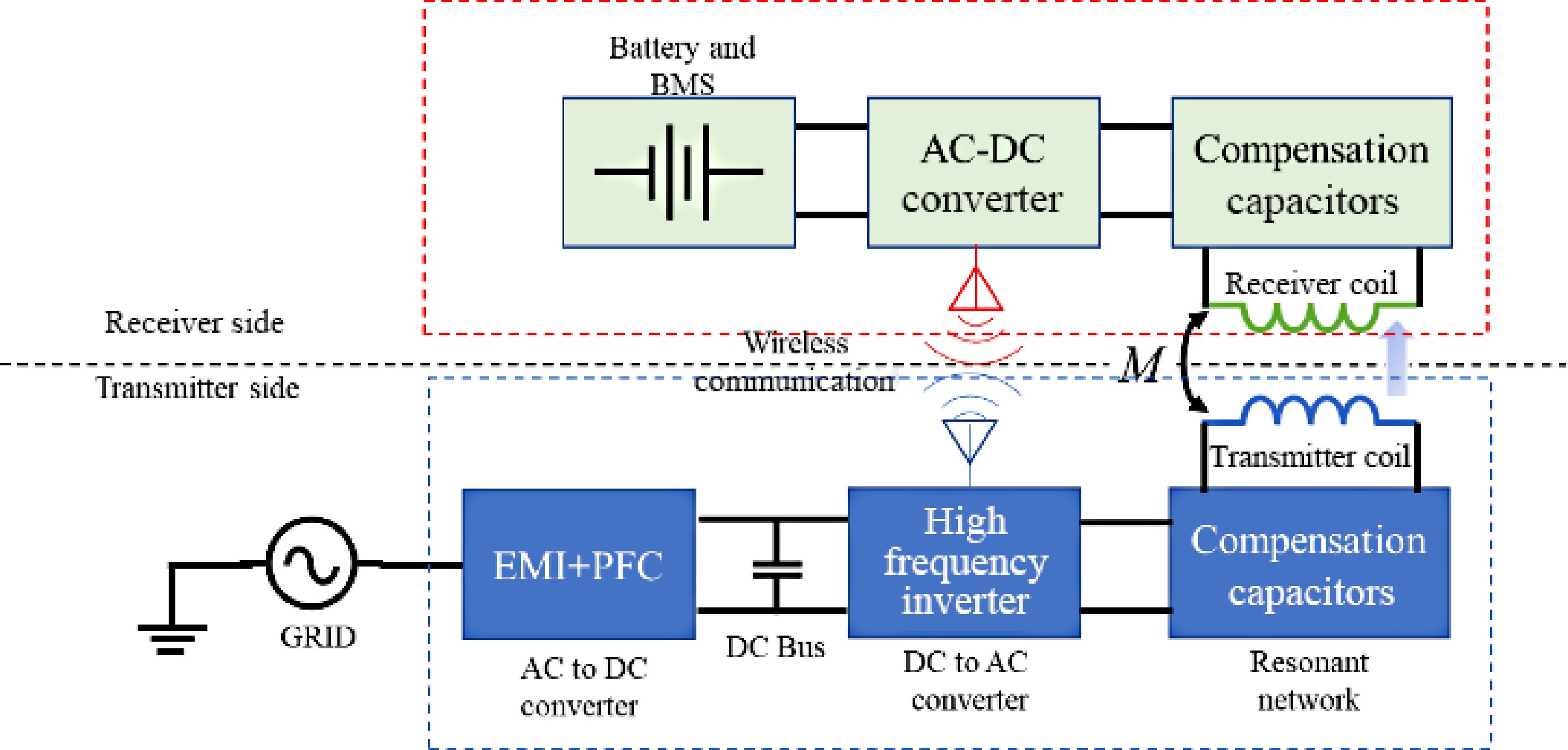
    • Wireless power transfer, especially via resonant inductive power transfer (RIPT), is becoming increasingly popular for charging various devices such as Electric Vehicles (EVs), Unmanned Aerial Vehicles (UAVs), and consumer electronics such as cellphones[1,2]. This technology offers users a safe and efficient charging experience. With the charging process automated and free from constant user intervention, wireless charging addresses the range anxiety problem in electric vehicles and extends the flight time of UAVs[3,4]. For consumers, eliminating charging cables means no more hassle and clutter, keeping their charging areas clean and organized. Figure 1 shows the block diagram of a typical RIPT-based wireless charger.

      Figure 1. 

      Block diagram of RIPT based wireless charger.

      In Fig. 1, power is transferred from the transmitter to the receiver through resonant inductive coupling. It consists of two inductors that are magnetically coupled through the principle of electromagnetic induction. The air gap between the transmitter and receiver inductors is significantly larger than a conventional transformer. To improve the system's efficiency, both inductors are made to resonate with a bank of capacitors in the transmitter and receiver circuits. These capacitors can be connected to the inductors in a series, parallel, or a combination of series-parallel configuration, resulting in multiple resonant topologies.

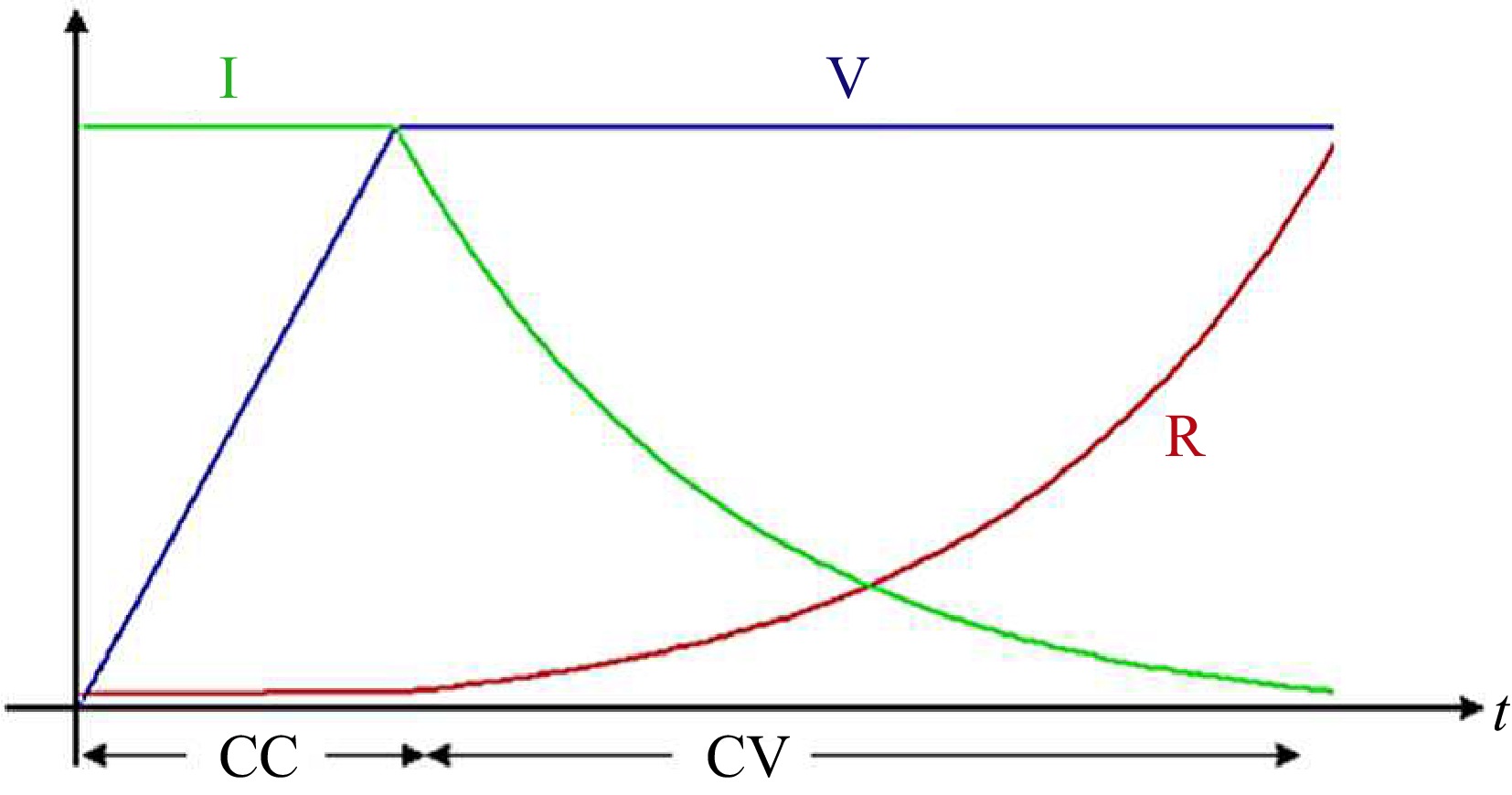
      For charging applications, load on the RIPT system is some kind of energy storage device. Due to their high energy density and power density, Li-ion batteries are a popular choice for energy storage devices in electric vehicles, UAVs, and consumer electronics[58]. Li-Ion batteries are charged using a Constant Current Constant Voltage (CC-CV) method which is shown in Fig. 2.

      Figure 2. 

      CC-CV charging operation.

      In Fig. 2, V represents the battery's rated voltage, I denotes the battery current and R indicates the equivalent resistance variation during the CC-CV charging operation of a lithium-ion (Li-Ion) battery. The battery is initially charged with a constant current until its terminal voltage reaches the rated voltage. Subsequently, the charger transitions to a constant voltage output, maintaining the terminal voltage until the battery achieves full charge. This charging technique, known as CC-CV (constant current-constant voltage), leads to an exponential rise in the terminal resistance observed by the charger, depicted by the red curve in Fig. 2. Consequently, the RIPT (Resonant Inductive Power Transfer) system must be controlled to operate in CC-CV mode.

      This paper presents a review of control methods applicable to RIPT systems for charging batteries using the CC-CV mode. Referring to Fig. 1, RIPT systems can be implemented in various configurations depending on the choice of the power converter and compensation topology, it is impractical to address control strategies for every circuit configuration. Therefore, this paper focuses solely on the control method for the Series-Series RIPT (SS-RIPT) system. For the DC-AC converter, H-Bridge topology and for AC-DC converter a Full-Bridge rectifier will be considered. The main contribution is identifying the control variables and utilizing them to achieve the CC-CV mode of operation.

      The control strategies for Resonant Inductive Power Transfer (RIPT) systems present a significant concern, and existing literature has yet to address all control strategies comprehensively in a single paper. There is a need for a thorough discussion of these strategies, including their advantages, limitations, and implementation examples, within a single paper. Addressing this gap is essential for advancing future research in this area, which underscores the importance of this review.

    • Figure 3 shows the SS-RIPT-based wireless charger[911]. In Fig. 3, only the DC to DC stage has been considered, and the front-end converter (EMI + PFC) stage has been neglected. In Fig. 3, the symbols VP and IP denote the primary side voltage and current, while VS and IS represent the secondary side voltage and current, respectively. LP and LS refer to the primary and secondary side inductances, and CP and CS indicate the primary and secondary side capacitances.

      Figure 3. 

      SS-RIPT based charger.

      Since the transmitter and receiver sides are mutually coupled through electromagnetic field, therefore battery voltage (VBatt) and battery current (IBatt) can be controlled directly by sensing the VBatt and IBatt or it can be controlled indirectly by sensing the current and voltage of the resonant tank such as IP, VP, IS, and Vs. Figure 4 shows the electrical equivalent circuit of the SS-RIPT link.

      Figure 4. 

      Simplified equivalent circuit of the SS-RIPT system.

      In Fig. 4, RL is the equivalent resistance of the battery seen by the secondary side, given by Eqn (1).

      (1)

      The fundamental components of VS and IS are related to VBatt and Ibatt respectively using Eqns (2) and (3).

      (2)
      (3)

      Referring to Fig. 4, at resonance,

      (4)
      (5)

      By utilizing Eqns (1)−(5), the relationship between battery voltage and current can be established with primary side voltage and current, as demonstrated in Eqns (6) and (7).

      (6)
      (7)

      Relationships in Eqn (2), (3), (6) and (7) can be utilized to control the battery voltage and current from the resonant tank variables.

      It should be noted that battery current/voltage can also be controlled indirectly by sensing DC link voltage VDC and DC link current IDC. However, for this article, the sole focus was on direct control by sensing VBatt and IBatt and indirect control by sensing resonant tank variables. Figure 5 shows the overall block diagram of the CC-CV controller.

      Figure 5. 

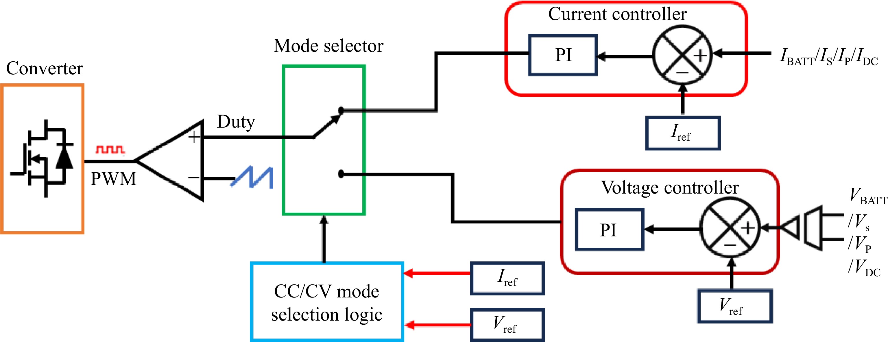
      CC-CV controller.

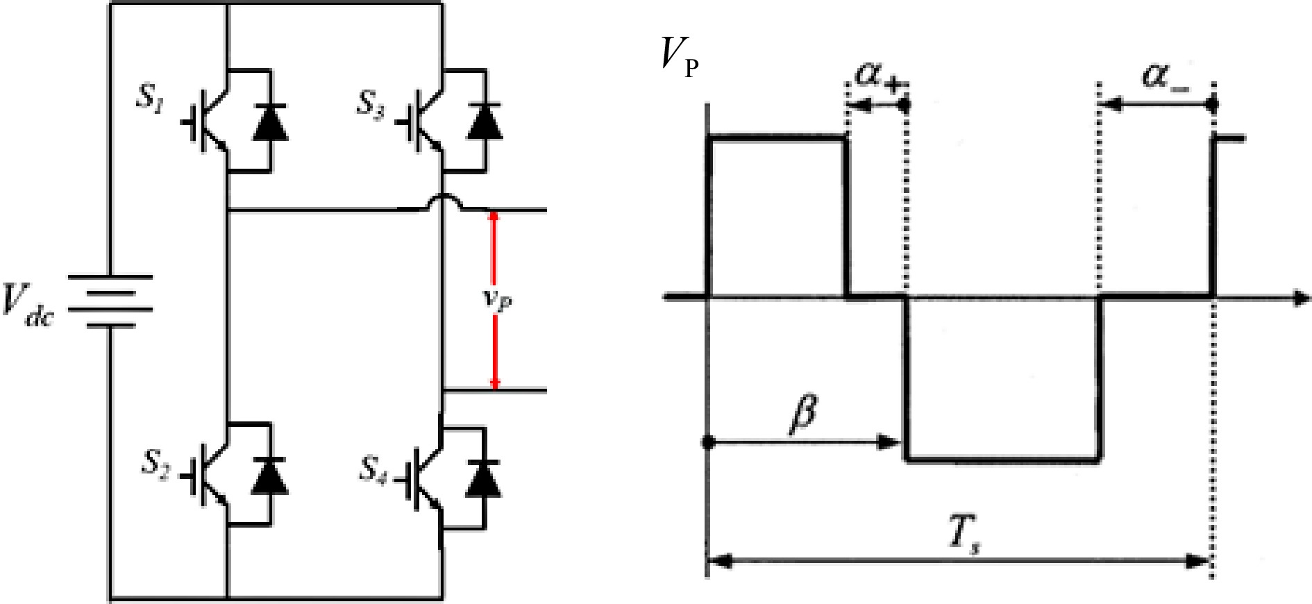
      In Fig. 5, a voltage/current controller enables the comparison between the measured output voltage/current and the desired values. The outputs of the controller determine the duty cycle for the PWM (Pulse Width Modulation) modulator. This duty cycle is then compared with a ramp signal to generate PWM pulses for the inverter or rectifier, which charges the battery. The PWM block generates a quasi-square wave at the output of the converter as shown in Fig. 6.

      Figure 6. 

      Quasisquare output voltage waveform of a resonant inverter.

      As shown in Fig. 6, output voltage and thus current can be regulated by four control variables α+, α-, and β, and the switching period (Ts). Three types of PWM are possible namely: Symmetric Voltage Cancellation (SVC) also known as Phase shift (PWM), Asymmetrical Voltage Cancellation (AVC), and Asymmetrical Duty Cycle (ADC). Detailed descriptions of these PWM techniques have been previously reported[12,13]. In Fig. 5, a selection logic is incorporated to switch between Constant Current (CC) and Constant Voltage (CV) modes based on the battery's state of charge.

      Control strategies in resonant inductive power transfer (RIPT) systems are primarily classified into three types, depending on which side's converter is being controlled: primary side control, secondary side control, and dual side control. Primary side control involves regulating the converter of the transmitter (i.e., the DC-AC converter), while secondary side control focuses on managing the converter of the receiver side (i.e., the AC-DC converter). Dual side control, on the other hand, entails controlling both the transmitter and receiver converters simultaneously.

      Based on the choice of control signal (reference signals), Table 1 categorizes the control method for SS-RIPT chargers. In Table 1, direct refers to sensing the battery voltage and current directly for feedback and indirect control refers to sensing signal other than load (battery) voltage and current.

      Table 1.  Classification of control method for SS-RIPT systems.

      Type of control Control variables
      Direct control Primary side, direct control VBatt, IBatt
      Secondary side, direct control VBatt, IBatt
      Indirect control Primary side, indirect control (VP, IP) or (VS, IS)
      Secondary side, indirect control (VP, IP) or (VS, IS)

      Existing primary side direct control strategies typically rely on wireless communication modules, such as Wi-Fi and ZigBee. In these strategies, charging information is wirelessly transmitted from the secondary side to the primary side and is then used as reference signals for the controller. Although this is a well-established technical solution, many studies have thoroughly analyzed the primary side direct control methods[1417], and certain challenges persist. These challenges include the additional cost of hardware and software for wireless communication modules, potential communication instability due to strong magnetic field interference, and the unsuitability of wireless communication for specific applications such as underwater or aerospace environments.

      To address these issues, some studies have introduced primary side indirect control methods. In Madawala et al.[18], the output power is regulated through the power-frequency droop characteristic of the wireless charging system, eliminating the need for a dedicated communication link. In Chow et al.[19], transmitter-side electrical information is used to regulate the power consumption on the receiver side. However, these methods focus solely on adjusting the output power without addressing the control of charging current and voltage. In Madawala & Thrimawithana[20], a phase-shifted full-bridge inverter is used to achieve constant voltage (CV) charging for the RIPT system, based on the estimated charging voltage from the primary side. However, no further analysis of constant current (CC) charging is provided. In Song et al.[21], while the primary side controller is capable of CC/CV charging for the SS/SP compensated RIPT system, it requires the estimation of load resistance and mutual inductance to control the charging current and voltage. This, in turn, necessitates additional hardware for load resistance estimation and mutual inductance identification, increasing system complexity and overall cost. In Li et al.[22], a primary side indirect control method is proposed to achieve CC/CV charging for the SS compensated RIPT system without the need for load identification, mutual inductance estimation, or dual-side communication.

      This review discusses both direct and indirect control strategies. For the indirect control strategy, rather than employing the complex approaches mentioned in the references, a more simplified method is adopted. This method involves deriving equations that establish the relationship between battery current and voltage with the primary and secondary tank currents and voltages, enabling effective control of the battery voltage and current.

      The authors acknowledge that dual-side control is also widely used, especially in bidirectional power transfer applications[2325]. However bidirectional control is not the focus of the current paper and will be covered separately in a different study.

    • In direct control, the battery is charged by directly sensing the battery voltage and current, utilizing them as feedback signals for the controller. Depending on whether PWM is controlling the primary-side converter or the secondary-side converter, direct control can be classified into two categories: Primary-side direct control and secondary-side direct control. Both types are elaborated on in the subsequent subsection.

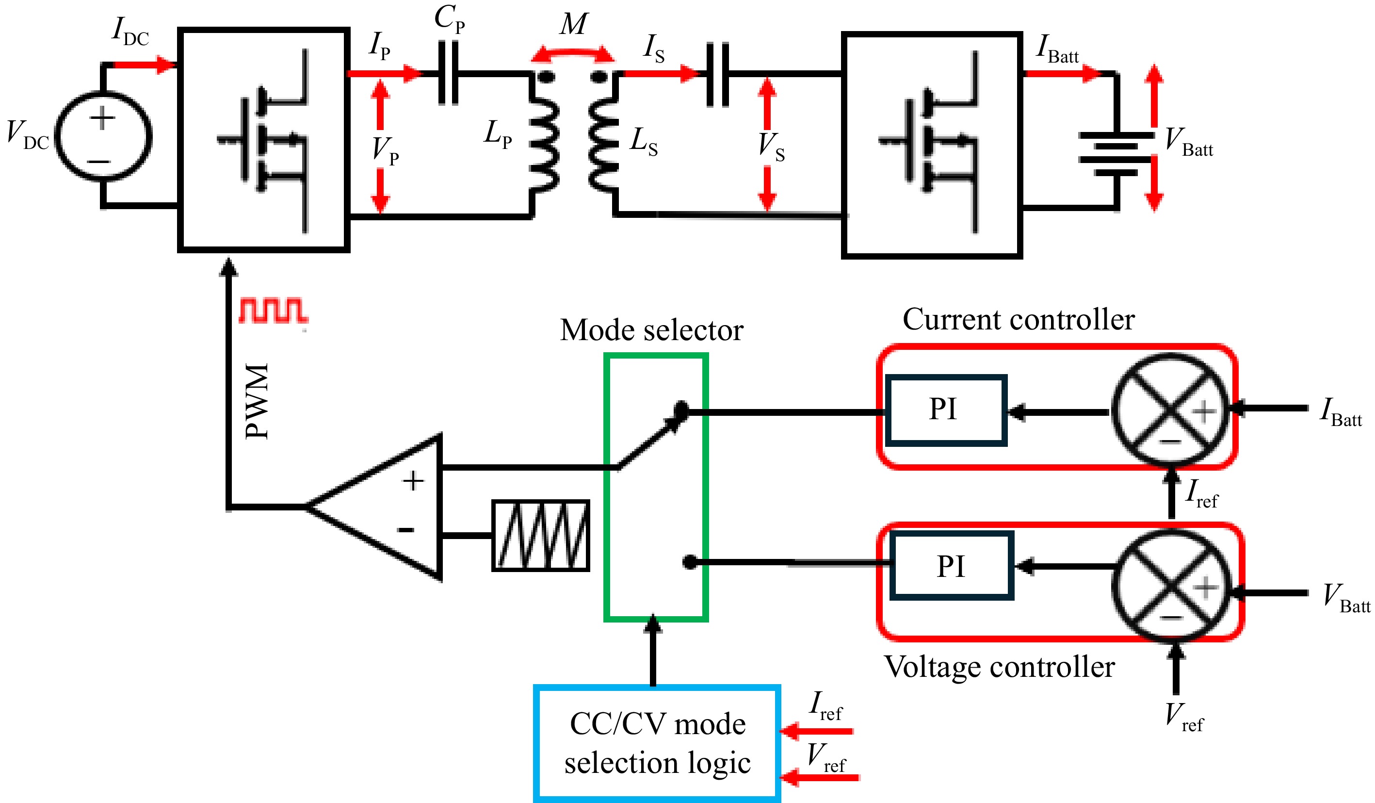
    • This is a very straightforward and easy-to-implement control technique. Figure 7 shows the block diagram of the primary side direct control of the SS-RIPT charger. VBatt and IBatt are used as the feedback signal for the CC-CV controller shown in Fig. 4. PWM signals generated from the CC-CV controller are used to adjust the primary side inverter output to control the voltage and current applied to the battery[15,26,2729]. The secondary side converter could be a simple uncontrolled rectifier or should be switched to 50% duty cycle in the case of an active rectifier.

      Figure 7. 

      Primary side direct contro.

      By utilizing Eqns (6) and (7), VBatt and IBatt can be manipulated by controlling IP and VP, respectively. To achieve this, a voltage control loop will generate PWM to regulate the output voltage of the inverter, ensuring that IP remains constant, thus operating the charger in CV mode. Similarly, for CC mode, a current control loop will generate PWM to maintain a constant VP, thereby supplying the battery with a constant IBatt.

    • Figure 8 shows the block diagram of the secondary side direct control scheme of the SS-RIPT system.

      Figure 8. 

      Secondary side direct control.

      In Fig. 8, the primary side converter operates at a fixed 50% duty cycle to achieve a square waveform. The secondary side converter functions as an active rectifier[3034]. For this control method to operate effectively, the secondary resonant tank must be slightly inductive[12]. PWM regulates the IBatt and VBatt through Eqns (2) and (3).

    • In indirect control, battery voltage and current are not used as feedback signals. Instead, primary, or secondary side resonant network variables are used as feedback signals of the CC-CV controller. Depending on whether PWM is controlling the primary-side converter or the secondary-side converter, direct control can be classified into two categories: Primary-side indirect control and secondary-side indirect control. Both types are elaborated on in the subsequent subsection.

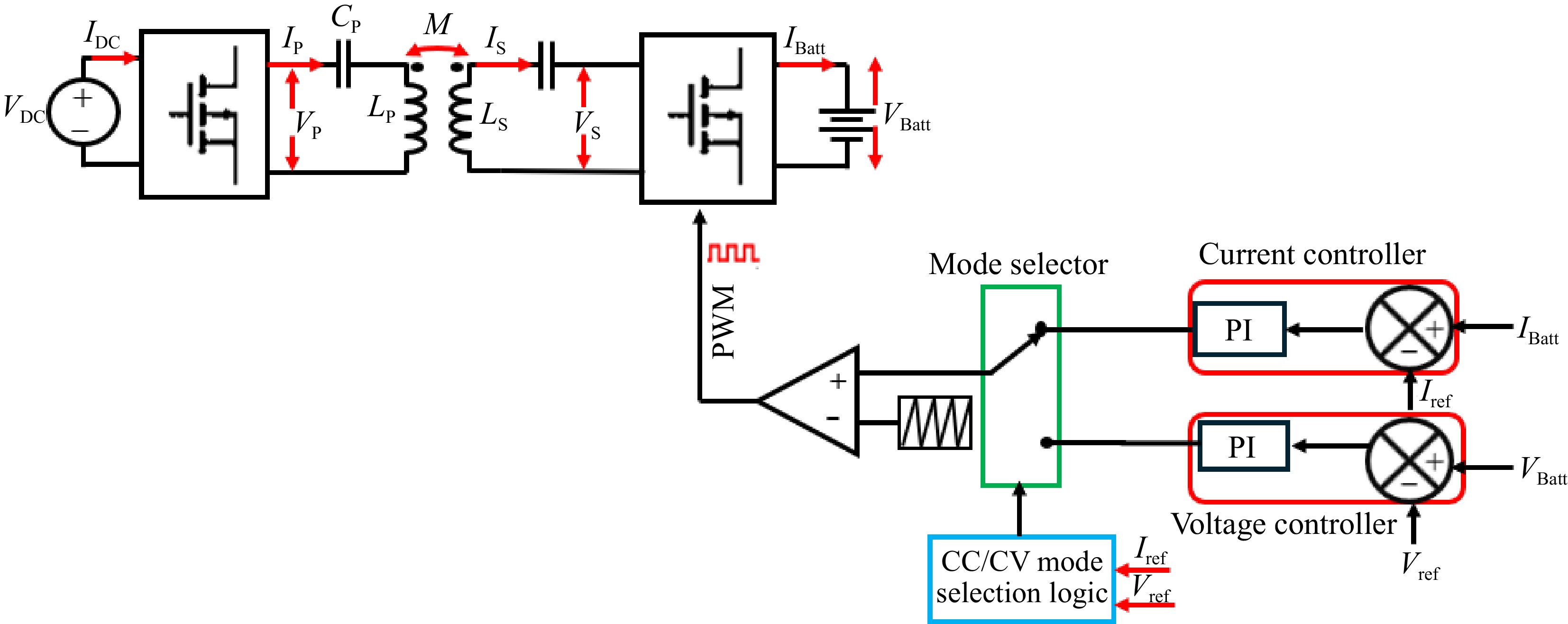
    • Figure 9 shows the block diagram of the primary side indirect control scheme of the SS-RIPT system.

      Figure 9. 

      Primary side indirect control.

      In Fig. 9, the average, RMS, or peak value of VP and IP are detected and used as feedback signals for the CC-CV controller. Figure 10 shows the block diagram representation of the average voltage control of the CC-CV controller[35,36]. Similarly, a current controller can be implemented. Equations (6) and (7) are applicable in this control.

      Figure 10. 

      Inverter output voltage regulation based on duty cycle control.

    • Figure 11 shows the block diagram of the secondary side indirect control scheme of the SS-RIPT system.

      Figure 11. 

      Secondary side indirect control.

      In Fig. 11, the primary side converter is operated at 50% duty cycle to obtain square wave output. The secondary side converter is operated as an active rectifier. Here the average, RMS, or peak values of VS and IS are detected and used as feedback signals for the CC-CV controller.

    • Existing literature indicates that both direct and indirect control strategies have distinct advantages and limitations. This section provides a comparison of these methods, focusing on their respective advantages and limitations.

      Table 2.  Comparison between direct and indirect control.

      Control strategy Advantages Limitations
      Primary side
      direct control
      It is a straightforward and easy-to-implement control method. The direct use of battery current and voltage as feedback signals for the CC-CV controller simplifies the process of sensing DC variables. This approach reduces the weight and complexity on the receiver side.
      • The dependence on wireless communication modules for information transmission incurs additional expenses associated with both hardware and software requirements
      • The transmitted information is vulnerable to errors, delays, and potential loss.
      • Strong magnetic field interference may cause instability in the communication process.
      Primary side indirect control • It eliminates the need for a dedicated communication module, thereby eliminating the risk of information loss.
      • The absence of a wireless communication module reduces the overall system cost.
      • Sensing primary side current and voltage at high frequencies, such as 100 kHz, is difficult due to the lack of readily available sensors with sufficient bandwidth.
      • Indirect control strategies estimate battery current and voltage through mathematical equations rather than direct measurement, which may lead to slight discrepancies between the estimated and actual values.
      Secondary side direct control • It provides precise and robust performance without the need for communication between the receiver and transmitter.
      • This approach facilitates the development of control systems aimed at enhancing efficiency and optimizing power charging.
      • This control approach results in increased weight and complexity on the receiver side.
      Secondary side indirect control • It does not require a dedicated communication module, thereby reducing the risk of information loss. • Sensing secondary side current and voltage at high frequencies, such as
      100 kHz, is difficult due to the lack of readily available sensors with sufficient bandwidth.
      • Indirect control strategies estimate battery current and voltage through mathematical equations rather than direct measurement, which may lead
      to slight discrepancies between the estimated and actual values.
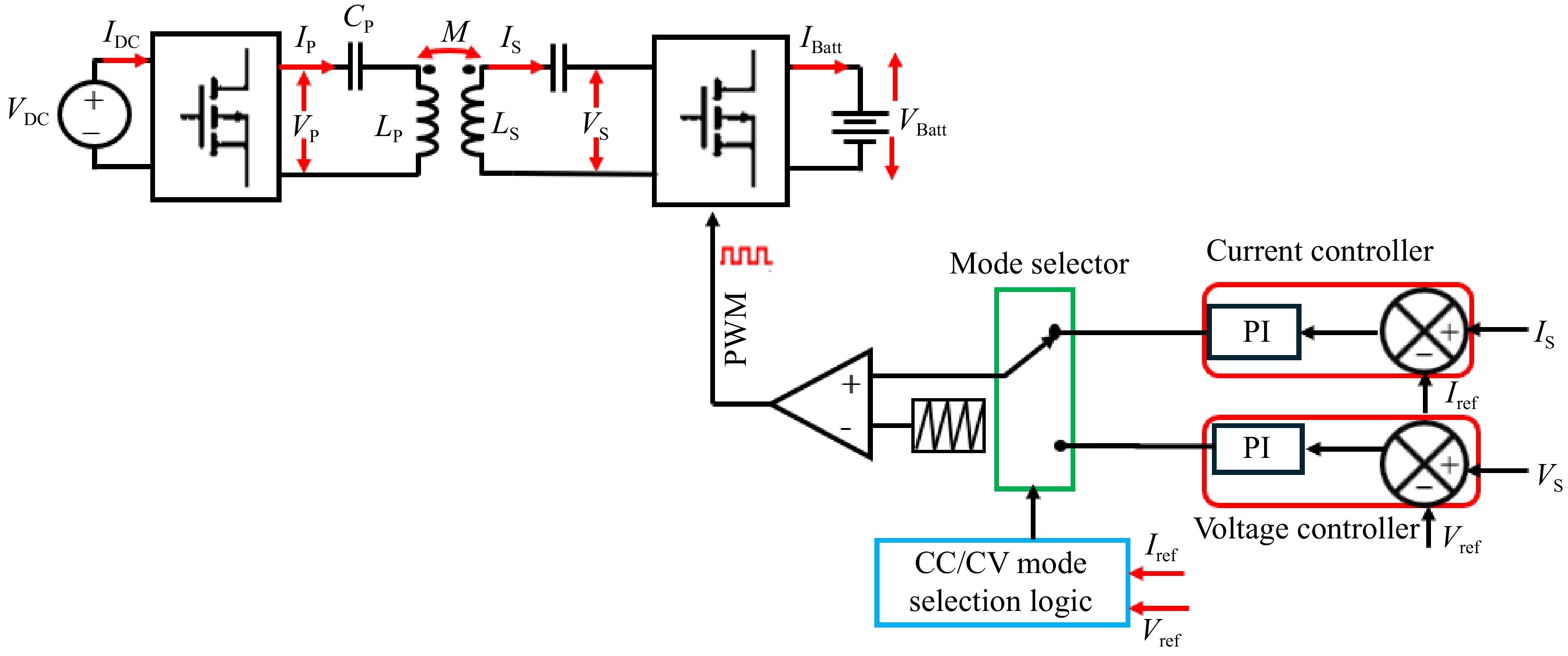
    • Implementing all four control strategies is technically possible; however, thoroughly addressing them in a single paper is not feasible. Therefore, this paper will concentrate on showcasing the simulation and Hardware in Loop Validation of two specific strategies: primary side indirect control for CC-CV charging of Li-Ion batteries and primary side direct control for CC-CV charging of Li-Ion batteries. The simulation involves an SS-RIPT based charger simulated in PLECS, with parameters outlined in Tables 3 & 4. A comprehensive simulation circuit for the primary side indirect control is illustrated in Fig. 12.

      Table 3.  Specification of the SS-RIPT-based charger.

      Parameters Values
      Input voltage, Vdc 24 V
      CV mode voltage, Vbatt,max 4.2 × 5 = 21 V
      CC mode current, Ibatt 5 A
      Minimum output voltage, VBatt,min 0.6 × 21 = 12.6 V
      Maximum output power, Pout 21 × 5 = 105 W
      Switching frequency, fsw 85 kHz

      Table 4.  Parameters of the SS-RIPT link.

      Parameters Values
      Primary inductance, LP 33.30 μH
      Secondary inductance, LS 39.73 μH
      Primary capacitance for 85 kHz, CP 105.27 nF
      Secondary capacitance for 85 kHz, CS 88.23 nF
      Mutual coupling 0.20
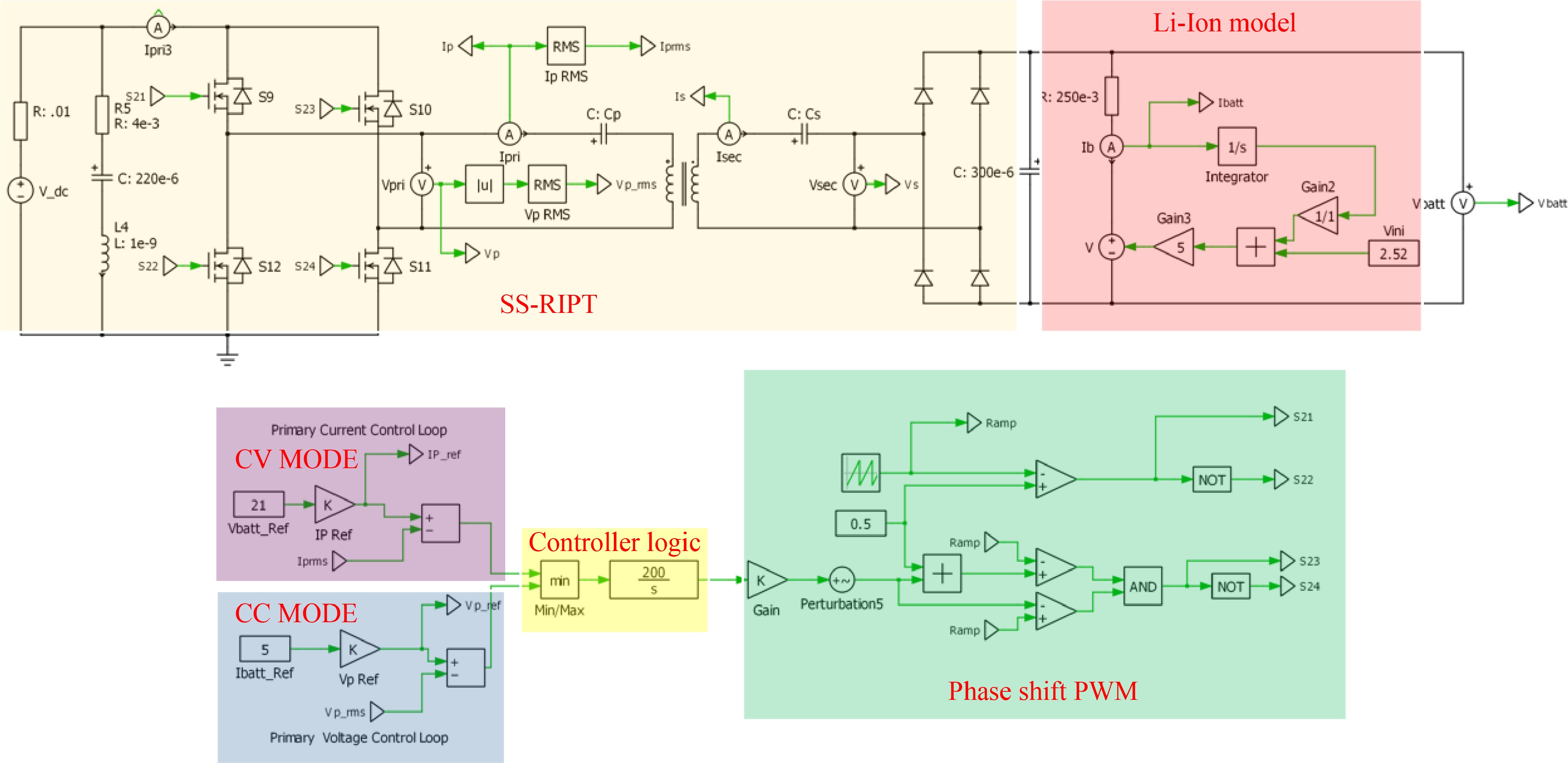
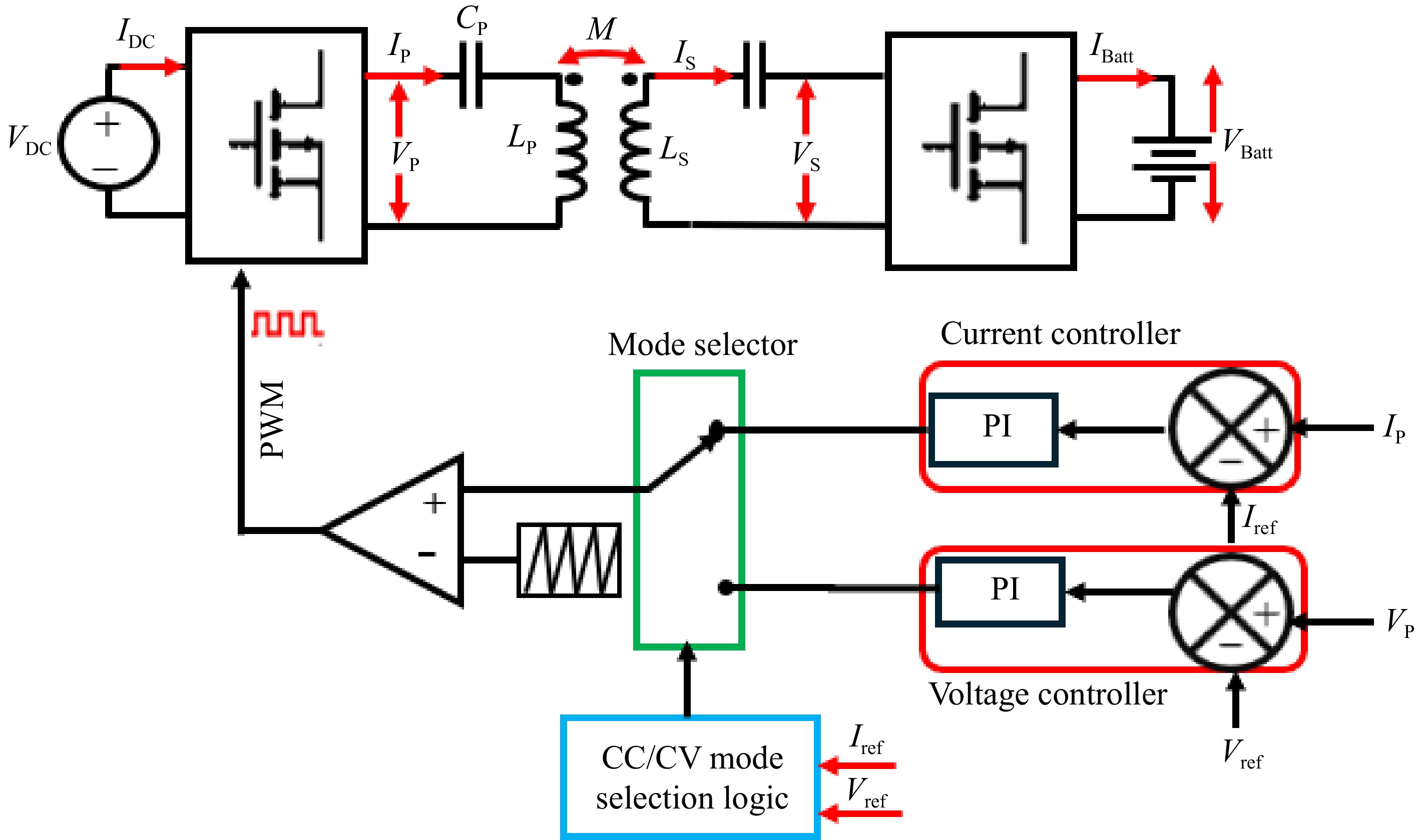
      Figure 12. 

      PLECS simulation circuit of primary side indirect control of an Li-Ion charger using CC-CV charging.

      In Table 2, the CC-CV charging profile has been decided based on 5,200 mAh 5S 25C/50C (18.5 V) Lithium Polymer battery pack[37,38].

      In Fig. 12, the RMS value of IP is sensed and used as feedback in the CV controller. For the CC controller, the RMS value of VP is sensed and used as feedback. As stated earlier, the average, RMS, or peak value could be used.

    • This section discusses the simulation of both direct and indirect primary side control methods. The results, exported from PLECS, are plotted in MATLAB for enhanced clarity. The findings are presented in two subsections: Primary side indirect control; and Primary side direct control.

    • In primary side indirect control, the primary side RMS voltage and RMS current are used to control VBatt and IBatt. Adjusting IBattREF modifies VPREF for the voltage controller while adjusting VBattREF modifies IPREF for the current controller.

      When IBattREF is changed from 5 to 3 A, the corresponding VPREF is adjusted, and VPRMS accurately tracks this change, as shown in Fig. 13a. Similarly, Fig. 14a demonstrates that VPRMS follows VPREF despite step changes in the load. Figures 13b & 14b illustrate the responses of VP and IP during these transitions.

      Figure 13. 

      Simulation result for voltage controller: (a) step change in IBattREF from 5 to 3 A to change the VPREF, (b) primary side voltage and current waveform for the same.

      Figure 14. 

      Simulation result for voltage controller: (a) change in load from 4.2 to 2 to 5 Ω, (b) primary side voltage and current waveform for the same.

      When VBattREF is changed from 21 to 12 V, the corresponding IPREF is adjusted, and IPRMS accurately tracks this change, as shown in Fig. 15a. Likewise, Fig. 16a demonstrates that IPRMS continues to follow IPREF despite step changes in the load. The responses of VP and IP throughout these transitions are shown in Figs 15b & 16b.

      Figure 15. 

      Simulation result for current controller: (a) step change in VBattREF from 21 to 12 V to change the IPREF, (b) primary side voltage and current waveform for the same.

      Figure 16. 

      Simulation result for current controller: (a) change in load from 4.2 to 2 to 5 Ω, (b) Primary side voltage and current waveform for the same.

      By replacing the load resistor with a Li-ion battery model designed in PLECS, as shown in Fig. 12, both controllers can operate together using logic to control the CC-CV mode of operation. The resulting performance is illustrated in Fig. 17.

      Figure 17. 

      CC-CV charging profile.

    • In the primary side direct control approach, the VBatt and IBatt serve as key feedback inputs for the CC-CV controller. This controller, in turn, orchestrates the generation of the appropriate PWM signals. These signals finely tune the output of the primary side inverter, thereby precisely regulating the voltage and current delivered to the battery, ensuring optimal charging performance.

      When VBattREF is adjusted from 21 to 10 V and subsequently to 18 V, the corresponding VBatt accurately tracks these changes, as illustrated in Fig. 18a. Similarly, Fig. 19a shows that IBatt continues to follow IBattREF despite step changes in the load. The responses of VP and IP during these transitions are depicted in Figs 18b & 19b.

      Figure 18. 

      Simulation result for voltage controller: (a) step change in VBattREF from 21 to 10 to 18 V, (b) primary side voltage and current waveform for the same.

      Figure 19. 

      Simulation result for voltage controller: (a) change in load from 4.2 to 8 Ω, (b) primary side voltage and current waveform for the same.

      Similarly, when IBattREF is adjusted from 5 to 2 A and subsequently to 4A, the corresponding IBatt accurately tracks these changes, as illustrated in Fig. 20a. Likewise, Fig. 21a demonstrates that IBatt continues to follow IBattREF despite step changes in the load. The responses of VP and IP during these transitions are shown in Figs 20b & 21b.

      Figure 20. 

      Simulation result for voltage controller: (a) step change in IBattREF from 5 to 2 to 4 A, (b) primary side voltage and current waveform for the same.

      Figure 21. 

      Simulation result for current controller: (a) change in load from 4.2 to 3 Ω, (b) primary side voltage and current waveform for the same.

      By replacing the load resistor with a Li-ion battery model designed in PLECS, as shown in Fig. 12, both controllers can operate together using logic to control the CC-CV mode of operation. The resulting performance is illustrated in Fig. 22.

      Figure 22. 

      CC-CV charging profile.

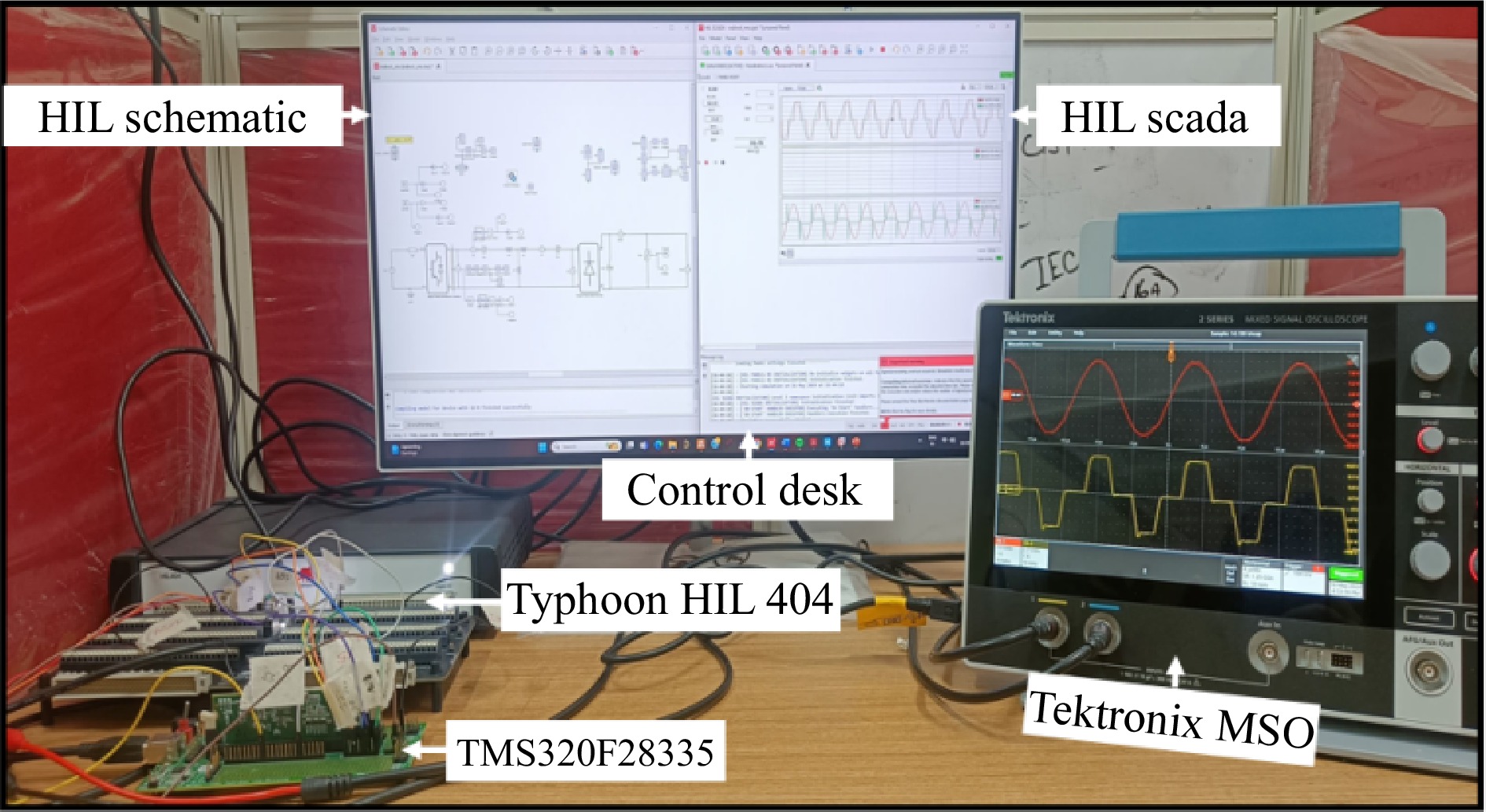
    • The proposed control strategy is validated through Hardware-in-the-Loop (HIL) simulation using Typhoon HIL, as illustrated in Fig. 23. A digital twin of the RIPT system is developed in Typhoon HIL, with the controller implemented on a Texas Instruments TMS320F28335 DSP. The results obtained from the Typhoon HIL simulation are exported and plotted in MATLAB for enhanced clarity.

      Figure 23. 

      Hardware in loop setup.

    • Figures 24 & 25 display the HIL results for the voltage controller validation, demonstrating strong agreement with the simulation results depicted in Figs 13 & 14 from PLECS. Similarly, Figs 26 & 27 exhibit the HIL results for the current controller, which closely align with the PLECS simulation results shown in Figs 15 & 16.
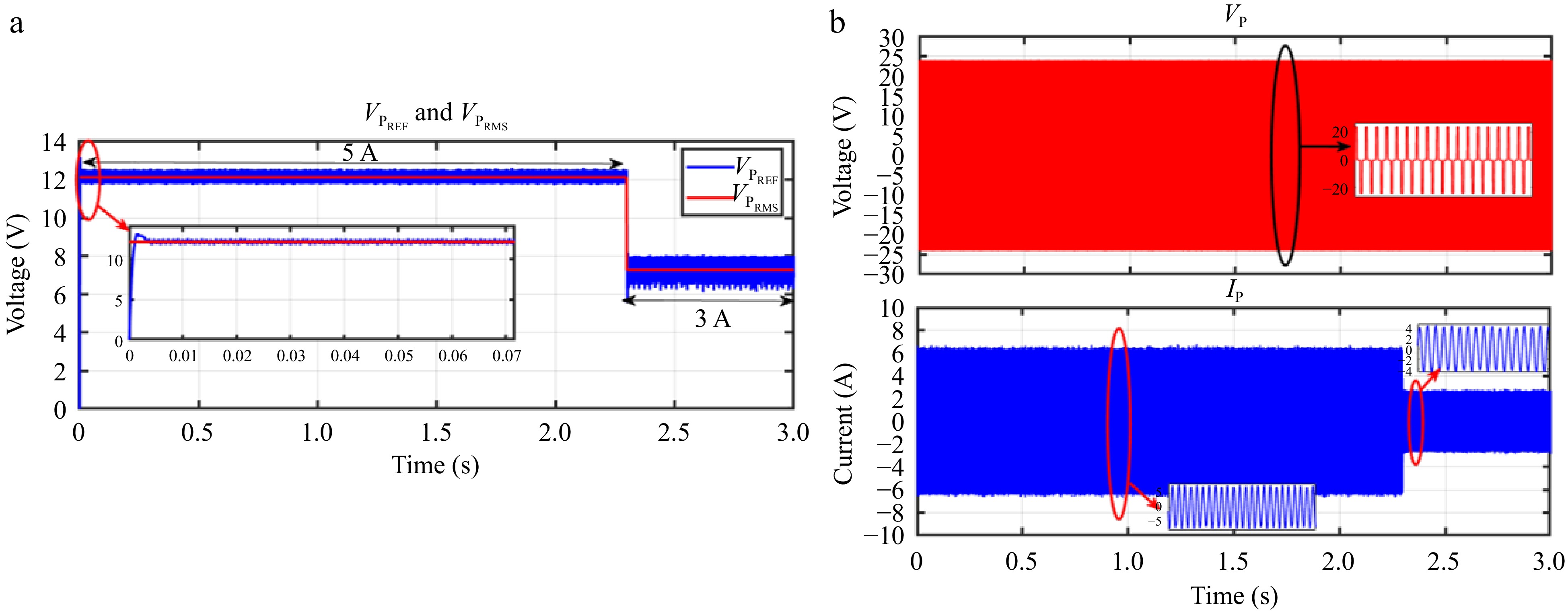
      Figure 24. 

      HIL result for voltage controller: (a) step change in IBattREF from 5 to 3 A to change the VPREF, (b) primary side voltage and current waveform for the same.
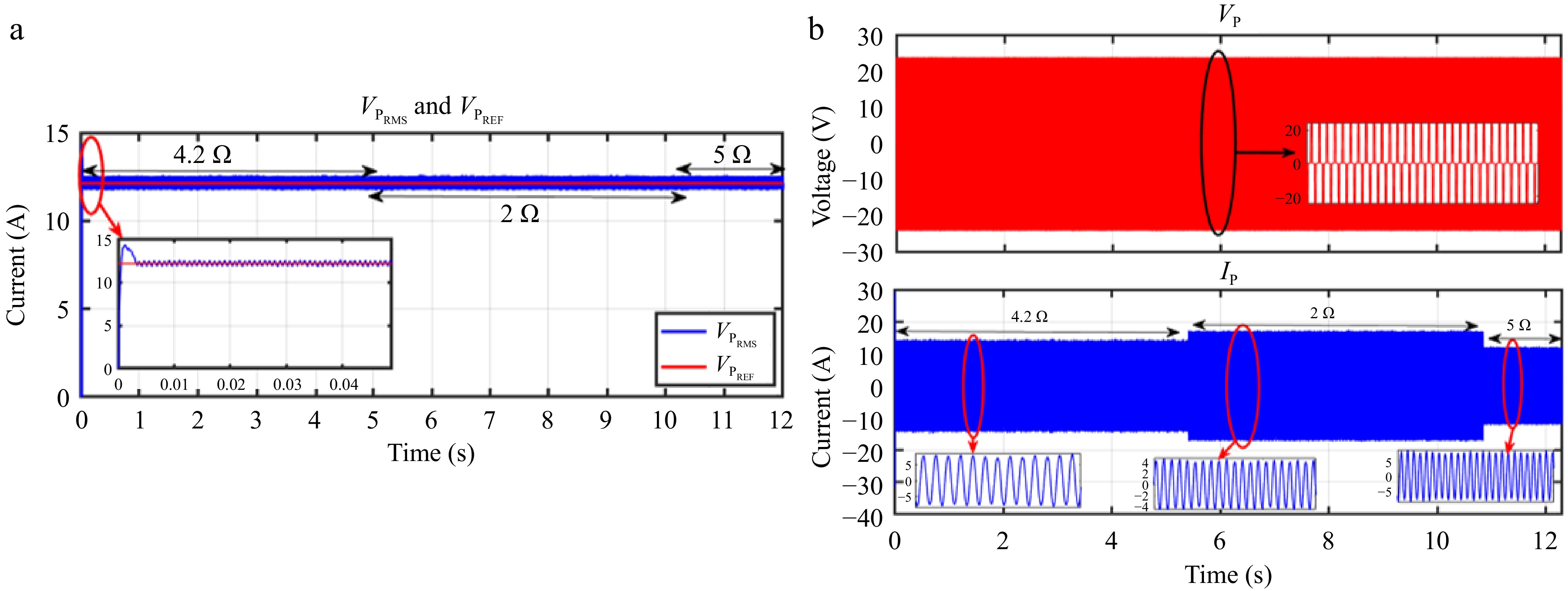
      Figure 25. 

      HIL result for voltage controller: (a) change in load from 4.2 to 2 to 5 Ω, (b) primary side voltage and current waveform for the same.
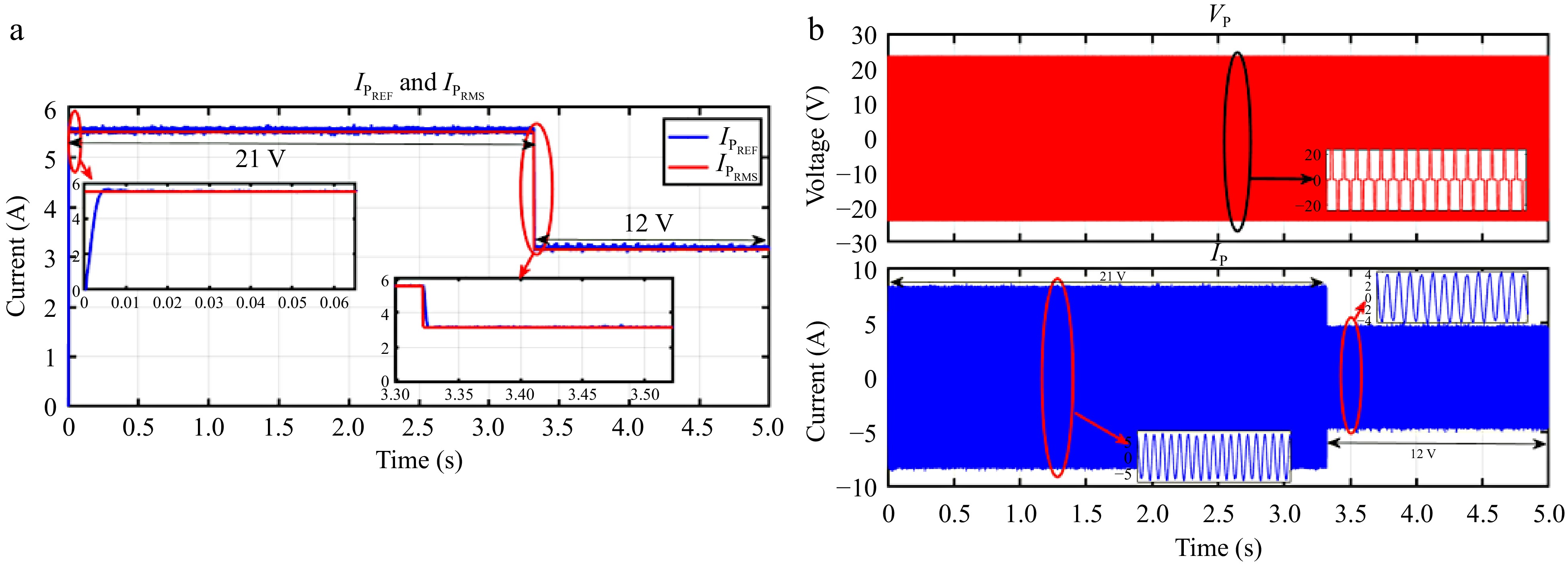
      Figure 26. 

      HIL result for current controller: (a) step change in VBattREF from 21 to 12 V to change the IPREF, (b) primary side voltage and current waveform for the same.
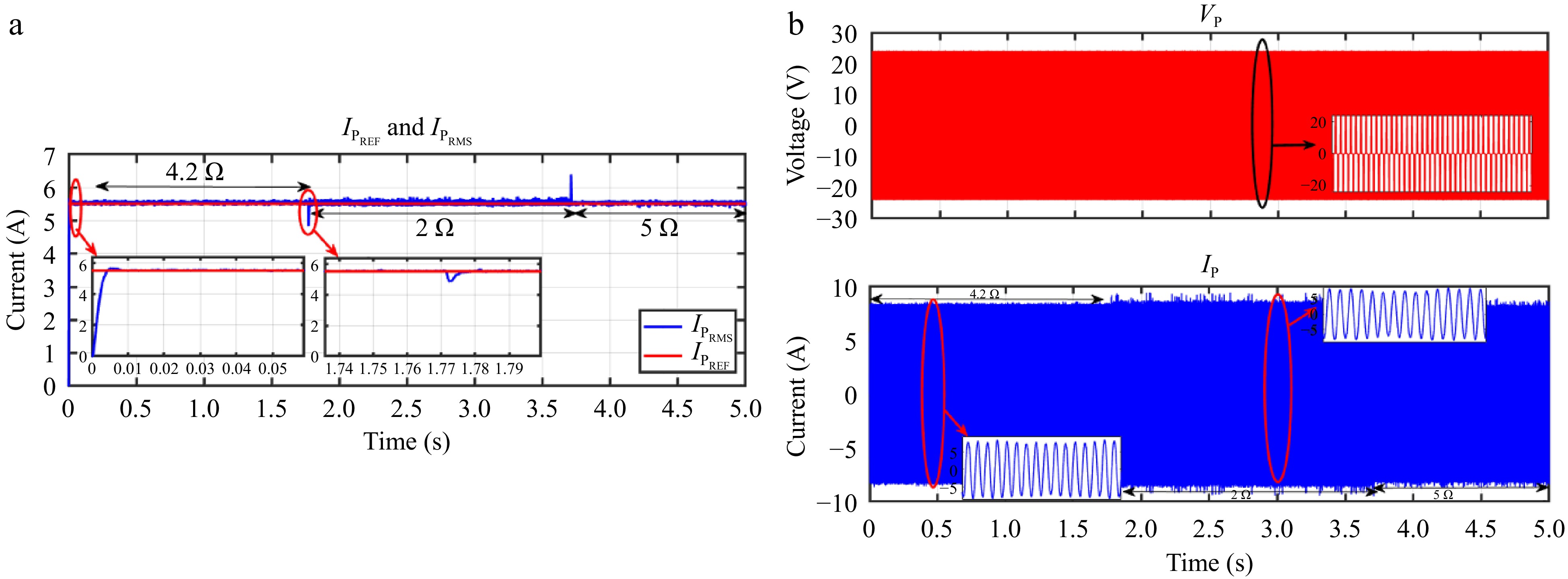
      Figure 27. 

      HIL result for current controller: a) change in load from 4.2 to 2 to 5 Ω, (b) primary side voltage and current waveform for the same.

    • Figures 28 & 29 present the HIL results for the voltage controller validation, showing a strong correlation with the simulation results from PLECS depicted in Figs 18 & 19. Similarly, Figs 30 & 31 display the HIL results for the current controller, which closely align with the PLECS simulation results shown in Figs 20 & 21.

      Figure 28. 

      HIL result for voltage controller: (a) step change in VBattREF from 21 to 10 to 18 V, (b) primary side voltage and current waveform for the same.

      Figure 29. 

      HIL result for voltage controller: (a) change in load from 4.2 to 3 to 8 Ω, (b) primary side voltage and current waveform for the same.

      Figure 30. 

      HIL result for voltage controller: (a) step change in IBattREF from 5 to 2 to 4 A, (b) primary side voltage and current waveform for the same.

      Figure 31. 

      HIL result for current controller: (a) change in load from 4.2 to 2 to 3 Ω, (b) primary side voltage and current waveform for the same.

      A model of a Li-ion battery was created in PLECS to validate the CC-CV charging technique. The emphasis during the HIL simulation was placed on showcasing how the system adapts to changing loads, thereby underlining the effectiveness and dependability of the implemented control approach.

    • In conclusion, wireless power transfer, particularly through resonant inductive power transfer (RIPT), is gaining momentum as a convenient and efficient method for charging a variety of devices including Electric Vehicles (EVs), Unmanned Aerial Vehicles (UAVs), and consumer electronics such as cell phones. This technology not only provides a safe and efficient charging experience but also addresses issues such as range anxiety in EVs and extending the flight time of UAVs by eliminating the need for constant user intervention during charging. Moreover, the absence of charging cables reduces clutter and keeps charging areas organized for consumers.

      The paper reviewed control methods applicable to RIPT systems for charging batteries using the Constant Current Constant Voltage (CC-CV) mode, focusing primarily on the series-series RIPT (SS-RIPT) system. It presented various control strategies, including direct and indirect control methods, and discussed their implementation for both primary and secondary sides of the RIPT system. While acknowledging the widespread use of bidirectional power transfer, the paper concentrated solely on unidirectional power transfer and left bidirectional control for future research.

      This paper primarily addresses the details of primary side indirect and primary side direct control for CC-CV charging of Li-ion batteries. Both control strategies were simulated using PLECS and verified through HIL results with the DSP controller TMS320F28335 and Typhoon HIL. The feasibility and effectiveness of both controls were demonstrated through simulations and analysis, providing valuable insights for practical implementation.

      Overall, this study contributes to the understanding of control strategies for RIPT systems, particularly in the context of CC-CV charging, and provides a foundation for further research and development in this field. As wireless power transfer continues to evolve, such studies are crucial for optimizing charging efficiency, improving user experience, and advancing the adoption of wireless charging technology across various applications.

    • The authors confirm contribution to the paper as follows: study conception and design: Munsi A, Pradhan S; data collection: Munsi A, Pradhan S; analysis and interpretation of results: Munsi A, Pradhan S, Aditya K; draft manuscript preparation: Munsi A, Aditya K. All authors reviewed the results and approved the final version of the manuscript.

    • All data included in this study are available upon request from the corresponding author.

      • This research work is funded by the SEED Grant, IIT Jodhpur with grant no: I/SEED/KUA/20220126.

      • The authors declare that they have no conflict of interest. Kunwar Aditya is the Editorial Board member of Wireless Power Transfer who was blinded from reviewing or making decisions on the manuscript. The article was subject to the journal's standard procedures, with peer-review handled independently of this Editorial Board member and the research groups.

      • Copyright: © 2024 by the author(s). Published by Maximum Academic Press, Fayetteville, GA. This article is an open access article distributed under Creative Commons Attribution License (CC BY 4.0), visit https://creativecommons.org/licenses/by/4.0/.
    Figure (31)  Table (4) References (38)
  • About this article
    Cite this article
    Munsi A, Pradhan S, Aditya K. 2024. Perspectives on control strategies for CC-CV charging in Resonant Inductive Power Transfer systems: a review of SS-RIPT configuration. Wireless Power Transfer 11: e009 doi: 10.48130/wpt-0024-0009
    Munsi A, Pradhan S, Aditya K. 2024. Perspectives on control strategies for CC-CV charging in Resonant Inductive Power Transfer systems: a review of SS-RIPT configuration. Wireless Power Transfer 11: e009 doi: 10.48130/wpt-0024-0009

Catalog

  • About this article

/

DownLoad:  Full-Size Img  PowerPoint
Return
Return