-
Inductive Power Transfer (IPT) is revolutionizing the convenience of energy conversion and the product value of a myriad of next-generation electrical and electronic consumer devices and applications[1−3]. Output power is a critical consideration for the practical implementation of IPT systems. High-power transfer ability provides the possibility to extend the power transfer distance. However, due to the loosely coupled transformer characteristics of IPT systems, the power transfer capability generally drops rapidly with transmission distance. The typical exponential decay curve of efficiency concerning the transfer distance (i.e., d) in a two-stage IPT system is shown in Fig. 1[4].
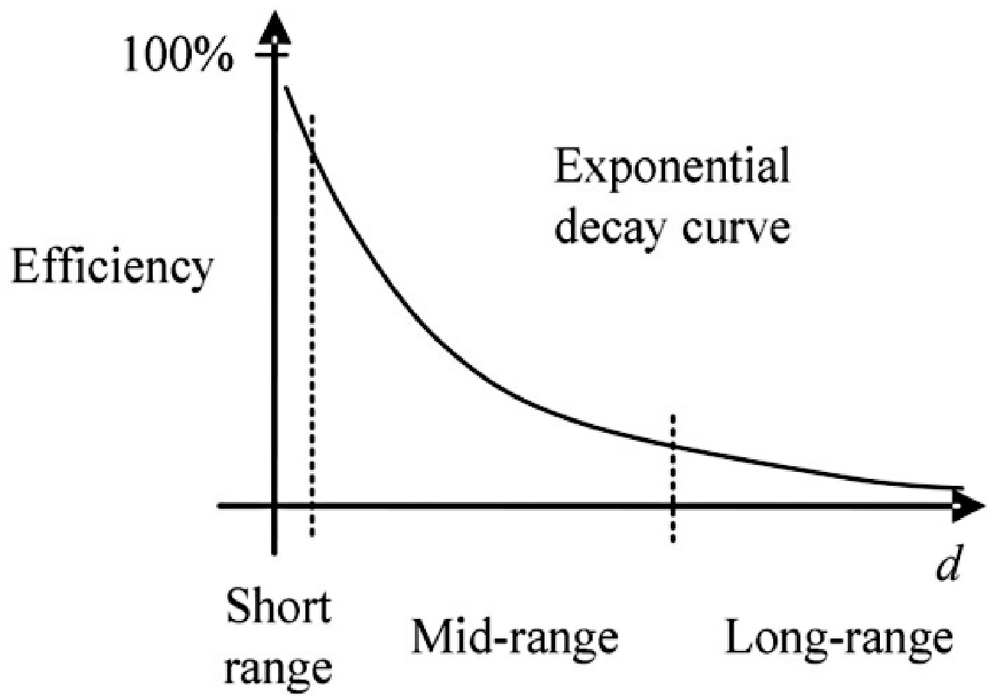
Figure 1.
Exponential decay curve of the efficiency as a function of transmission distance d for a two-stage IPT system[4].
To increase the power transfer distance, relay coils are employed in the IPT system. Relay coil-based IPT systems can be classified into three types: the four-coil IPT system[5−7], the three-coil IPT system[8−14], and the domino IPT system[15−17]. Among these types, in the domino IPT system, relay coils are typically placed in a fixed location, primarily applied to insulation. In contrast, the locations of relay coils for the three and four-coil IPT systems are relatively flexible. Relay coils have practical applications in WPT by enhancing transmission efficiency and range. They are used to extend charging distances in electric vehicle (EV) charging, enable simultaneous power supply to multiple devices in smart homes, improve charging efficiency for biomedical implants, and facilitating remote power delivery in harsh environments such as high-temperature industrial settings or underwater. Thus, relay coils are widely applicable in fields such as transportation, smart devices, industrial automation, and healthcare.
In 2007, an MIT team successfully transferred 60 W of power to the load over a 2 m transmission distance using a four-coil IPT system[5]. Subsequent studies revealed the pivotal role of the two additional coils in the four-coil WPT systems for impedance matching[6,7]. In the study by Chen et al.[6], a tuning method is implemented to transfer the required power with maximum efficiency. In the study by Cheon et al.[7], detailed explanations for the impedance matching of the four-coil IPT system to maximize power transfer are presented.
It is indicated in the research by Kiani et al.[8] that the three-coil WPT can achieve higher output power than the four-coil WPT system. And the three-coil WPT system is being implemented in implant devices[9−11]. Comparisons of the system efficiency between the two-coil and three-coil WPT systems are discussed in previous research[12−14].
Most existing research on relay coil systems has been conducted on conventional planar-type IPT systems, with insufficient investigations into spatial IPT systems. Relay coils show great potential for spatial IPT systems due to their beneficial power transfer characteristics. Spatial IPT systems exhibit excellent misalignment tolerance and allow for flexible placement of the receiver. The application of spatial IPT systems in containers has been widely studied[18−21]. In previous studies[18,19], the cavity transmitter adopts the form of an octagonal prism structure and cubic structure. These spatial IPT systems provide power to receivers located all around the container at a fixed angle. In the study by Mao et al.[20], a double-layer coil structure based on the octagonal prism structure has been proposed to uniform the magnetic field (B-field) distribution. In the study by Wang et al.[21], a folded coil design for the spatial IPT system based on the cubic and octagonal prism structure has been proposed.
However, wireless charging containers face the challenge of low power transfer capability due to the flexible locations of the receiver. Therefore, investigations into the use of relay coils in wireless charging containers are necessary. The wireless power transfer system with a wireless power modulator (WPM), as mentioned, has been widely applied to implant devices[10,11], and portable equipment. Additionally, cubic wireless charging containers have been used in small-scale applications, such as biomedical implants[11], and large-scale applications, such as wireless charging rooms[19]. One of the primary issues with wireless charging containers is that the received power is relatively low due to weak coupling and the small size of the receiver coil. Therefore, this paper proposes using a WPM in wireless charging containers to regulate power and improve the WPT system.
In this paper, a relay coil is implemented in a cubic wireless charging container which has a diameter of 1 m. The relay coil acts as a WPM capable of boosting or decreasing the output power. Two critical effects of the WPM, namely the resonant frequency of the WPM and the distance between the WPM and the transmitter and receiver, are analyzed. Different sets of experiments are conducted, and some interesting findings from the experiments are summarized.
-
In this section, the WPT system of the wireless power container configured with a WPM is theoretically analyzed. Firstly, the magnetic field inside the container is simulated and compared using Ansys Maxwell for the following scenarios: (1) Coil I working individually; (2) Coil II working individually; and (3) Both sets of coils working simultaneously. Then, the circuit of this WPT system is simplified and analyzed.
Analysis of magnetic field models inside the container
-
Following the folded coil design for the cubic wireless charging container proposed in previous research[21], the two coils (Coil I and Coil II) in the container are orthogonal in space and connected in series, as illustrated in Fig. 2. According to the study by Wang et al.[21], utilizing a 33% folding coil configuration within a cubic container results in a more uniform internal magnetic field with reduced deviation, making it a more suitable design for experimental purposes compared to other percentage configurations, so the folding ratio of each coil is set at 33%.
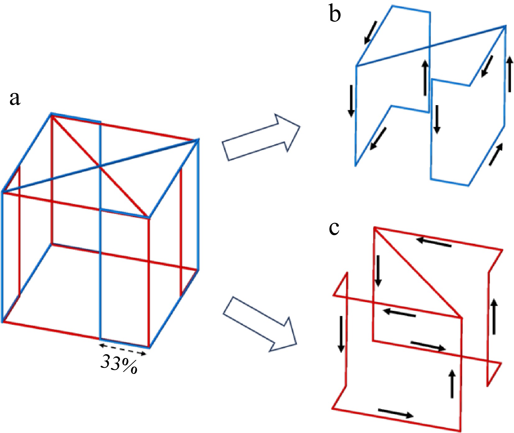
Figure 2.
Coil winding and current flow profile of the container. (a) WPT system for wireless charging incubator configured with a WPM, (b) Coil I in transmitter, (c) Coil II in transmitter.
The two orthogonal folding coils are capable of generating relatively uniform magnetic fields within the wireless charging container. Operation of a singular coil allows the receiver to harness significant energy in a specific direction (2π of solid angles), a phenomenon that will be substantiated through ensuing experimental validation. The concurrent operation of both coils, when connected in series, facilitates the synthesis of a magnetic field, thereby enabling the receiver to absorb significant energy from all directions (4π of solid angles). The distribution of the magnetic field inside the container, during the operation of one of the coils in the transmitter (Coil I & Coil II), is shown in Fig. 3.
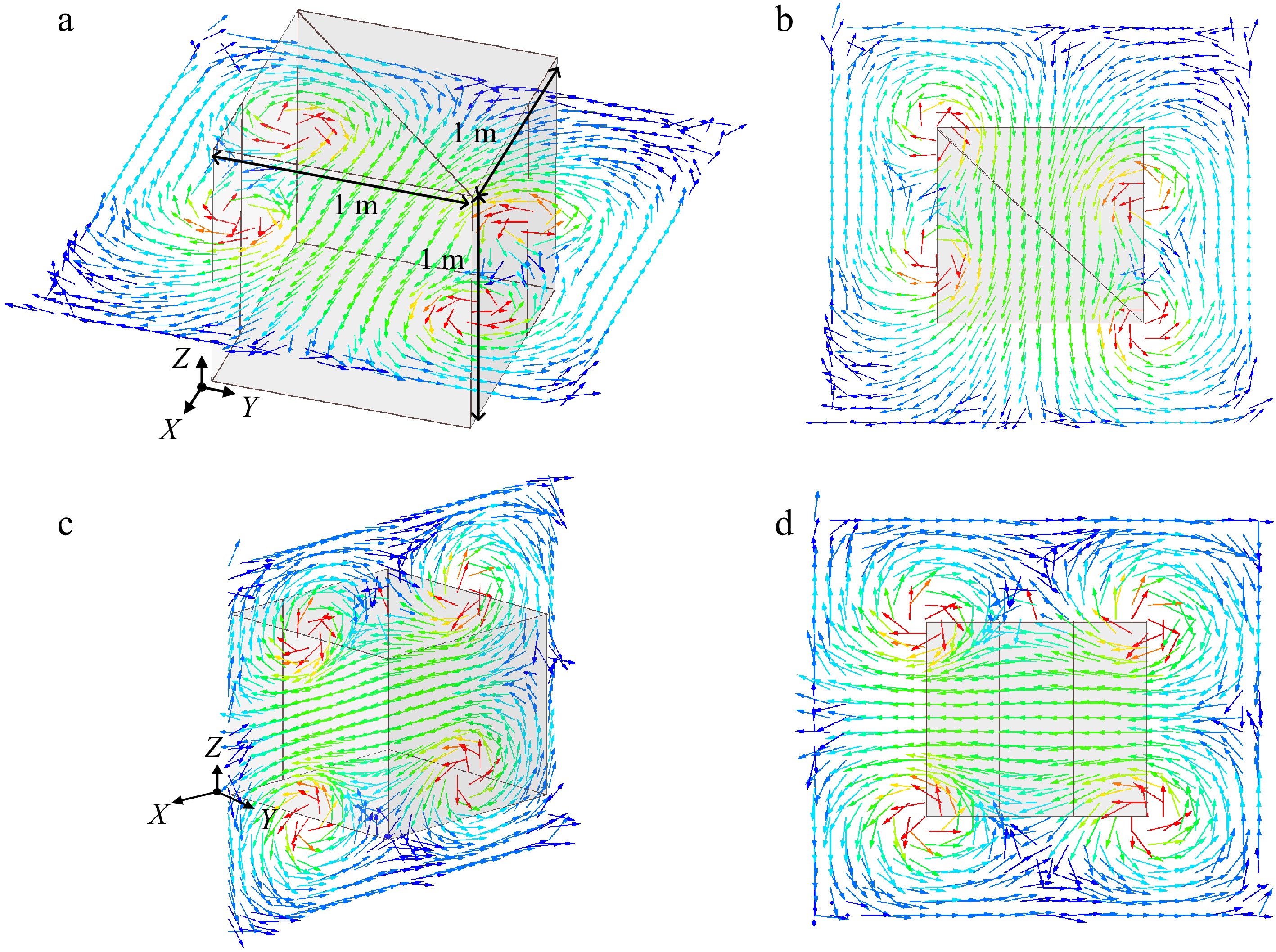
Figure 3.
Magnetic flux distribution inside the wireless charging container for one coil (Coil II for example) operation. (a) Horizontal plane, (b) top view of magnetic flux distribution, (c) vertical plane, (d) side view of magnetic flux distribution.
The transmitting coil utilized in this experiment consists of two orthogonal sets of coils. When an alternating current of identical frequency and phase is passed through these coils, it generates two orthogonal magnetic fields. These fields combine to form a single spatial magnetic field. As shown in Fig. 4, due to their perpendicular orientation, the magnetic fields do not interfere with each other but result in a 90° phase difference in the receiving coils. This configuration allows the receiver to capture the same amount of energy regardless of its orientation in perpendicular planes. To reduce the number of variables and simplify the experimental procedure, this study focuses on a single transmitting coil. In practical applications, the overall effect would be the superimposition of the two coils.
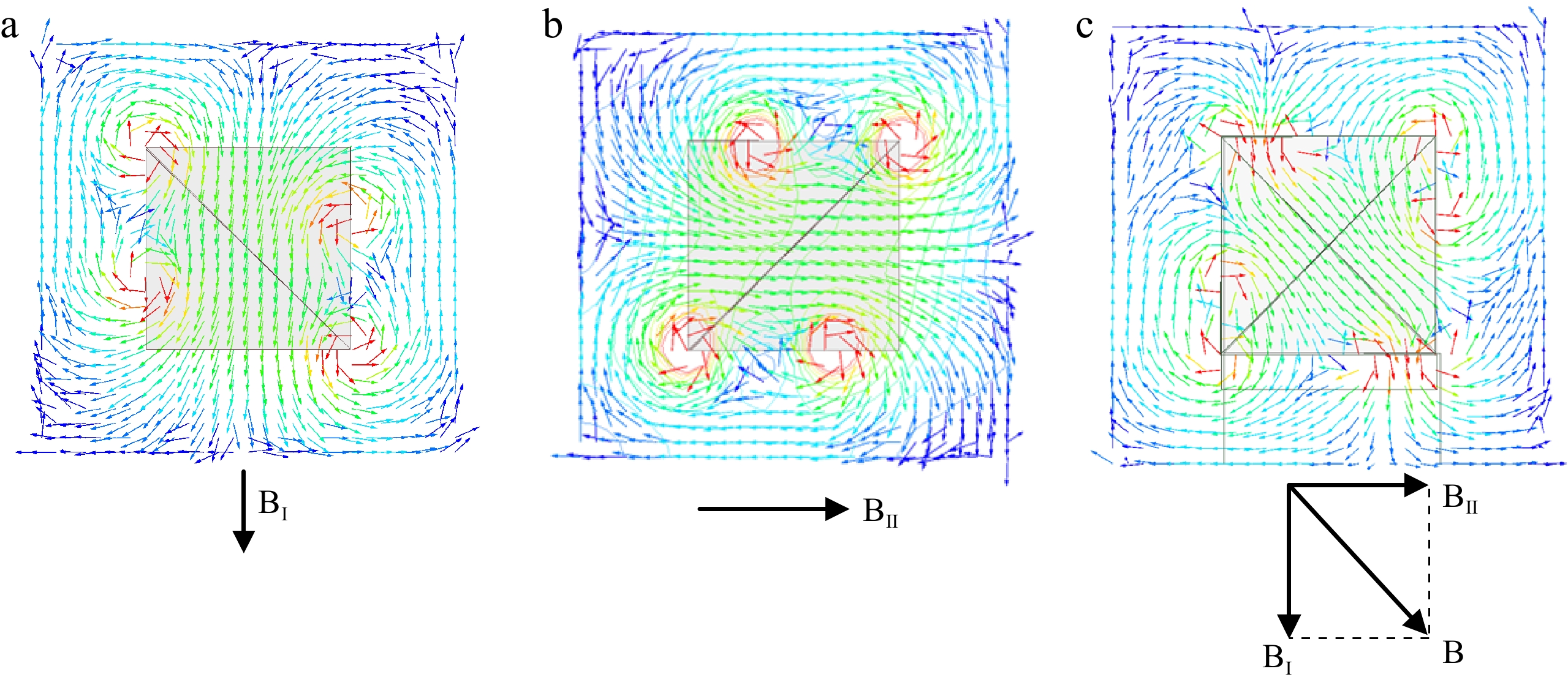
Figure 4.
Top view of magnetic flux distribution when different coils operating and their relationship. (a) Coil I operating, (b) Coil II operating, (c) Coil I and Coil II operating.
Analysis of circuit model for a wireless charging container configured with WPM
-
The equivalent circuit model of the WPT system with WPM can be simplified as a three-coil WPT system as shown in Fig. 5a, and the simplified equivalent circuit model is shown in Fig. 5b. The transmitter, WPM and receiver are adopted series compensated topology and the inductance for the transmitter, WPM, and receiver are denoted as L1, LM, and L2, respectively. C1, CM, and C2 are the compensated capacitors. M1M, M2M, and M12 represent the mutual inductance between L1 and LM, LM and L2, L1 and L2, respectively.
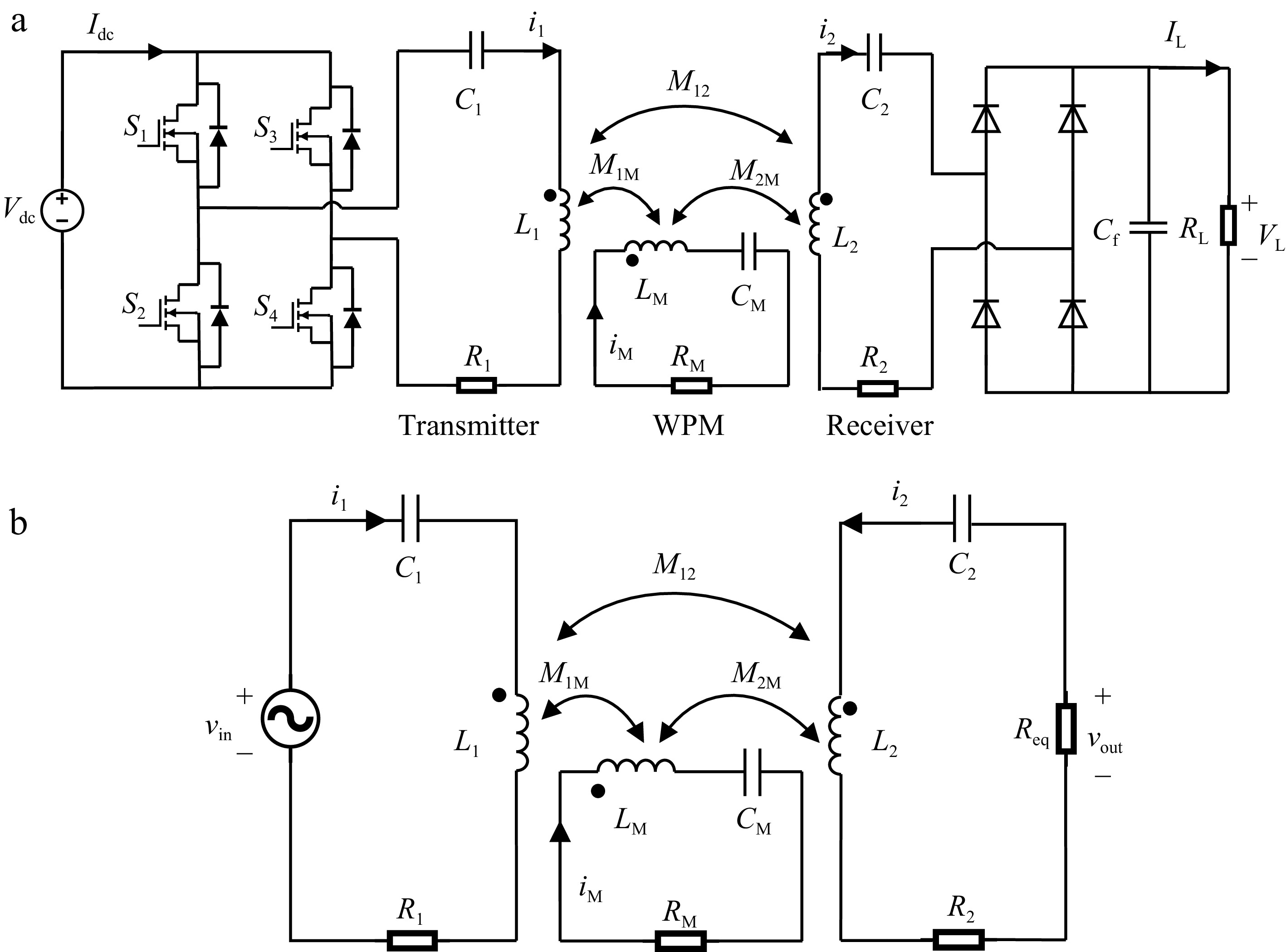
Figure 5.
(a) Equivalent circuit model for the proposed WPT system, and (b) the simplified circuit model.
This simplified model and the following equations already consider the possible ohmic losses caused by the power supply, the inverter and the rectifier. It also considers the cross-coupling between the receiver and transmitter coils. From the simplified circuit model in Fig. 5b, The impedance of the transmitter loop, the WPM loop and the receiver loop can be expressed respectively as:
$ {Z}_{1}={R}_{1}+j{\omega }_{0}{L}_{1}-\dfrac{j}{{{\omega }_{0}C}_{1}} $ (1) $ {Z}_{M}={R}_{M}+j{\omega }_{0}{L}_{M}-\dfrac{j}{{{\omega }_{0}C}_{M}} $ (2) $ {Z}_{2}={R}_{2}+{R}_{eq}+j{\omega }_{0}{L}_{2}-\dfrac{j}{{\omega }_{0}{C}_{2}}$ (3) where, Z1, ZM, and Z2 are the impedance of the transmitter loop, the WPM loop and the receiver loop respectively. According to Kirchhoff voltage law (KVL), the three loops in system can be expressed as:
$ \overrightarrow{{V}_{in}}={Z}_{1}\overrightarrow{{I}_{1}}+j{\omega }_{0}{M}_{1M}\overrightarrow{{I}_{M}}+j{\omega }_{0}{M}_{12}\overrightarrow{{I}_{2}} $ (4) $0=j{\omega }_{0}{M}_{1M}\overrightarrow{{I}_{1}}+{Z}_{M}\overrightarrow{{I}_{M}}+j{\omega }_{0}{M}_{2M}\overrightarrow{{I}_{2}} $ (5) $ 0=j{\omega }_{0}{M}_{12}\overrightarrow{{I}_{1}}+j{\omega }_{0}{M}_{2M}\overrightarrow{{I}_{M}}+{Z}_{2}\overrightarrow{{I}_{2}} $ (6) where,
$ \overrightarrow{{V}_{in}} $ $ {v}_{in} $ $ \overrightarrow{{I}_{1}} $ $ \overrightarrow{{I}_{M}} $ $ \overrightarrow{{I}_{2}} $ Then, the output current and power flow to the load P2 can be expressed as:
$ \overrightarrow{{I}_{2}}=-\dfrac{\left({k}_{1M}{k}_{2M}+j{k}_{12}{Q}_{M}\right)}{{[X}_{0}-2j\left({k}_{1M}{k}_{2M}{k}_{12}\right)]{\omega }_{0}{L}_{1}}\sqrt{\dfrac{{L}_{1}}{{L}_{2}}}\overrightarrow{{V}_{in}} $ (7) $ {P}_{2}={\left|\overrightarrow{{I}_{2}}\right|}^{2}{R}_{eq} $ (8) where,
$ {X}_{0}={k}_{1M}^{2}{Q}_{2}+{k}_{12}^{2}{Q}_{M}+{k}_{2M}^{2}{Q}_{1}+{Q}_{1}{Q}_{M}{Q}_{2} $ $ {k}_{1M}=\dfrac{{M}_{1M}}{\sqrt{{L}_{1}{L}_{M}}} $ $ {k}_{2M}=\dfrac{{M}_{2M}}{\sqrt{{L}_{2}{L}_{M}}} $ $ {k}_{12}=\dfrac{{M}_{12}}{\sqrt{{L}_{1}{L}_{2}}} $ $ {Q}_{1}=\dfrac{{Z}_{1}}{{\omega }_{0}{L}_{1}} $ $ {Q}_{M}=\dfrac{{Z}_{M}}{{\omega }_{0}{L}_{M}} $ $ {Q}_{2}=\dfrac{{Z}_{2}}{{\omega }_{0}{L}_{2}} $ The output power is dependent on the impedance of the transmitter, receiver, and the WPM, as well as the mutual inductance between the coils as can be seen from Eqns (7) & (8). For a given system with fixed coil parameters, the impedance can be regulated by adjusting the operating frequency. Here, to simplify the analysis and based on a practical IPT system, the resonant frequencies of the transmitter and receiver are set to be the same as the operating frequency. The resonant frequencies of the relay coil are set at different values. The mutual inductance of the coils is regulated by adjusting the placement of the WPM. The performance of the power flow regulation of the WPM is demonstrated in the experiment.
-
Two different types of experiments for the WPT system with WPM were conducted. In the first type of experiment (Experiment A), the resonant frequencies for the transmitter, WPM, and receiver are set the same. In the second type of experiment (Experiment B), the resonant frequency for the WPM is intentionally set differently from the resonant frequency of the transmitter and receiver. It has been proposed by Yang et al.[22] that biasing the frequencies of the WPM differently from the transmitter and receiver can regulate the output power capability. Hence, different resonant frequencies of the WPM are designed in this paper to explore their performance in the cubic wireless charging container.
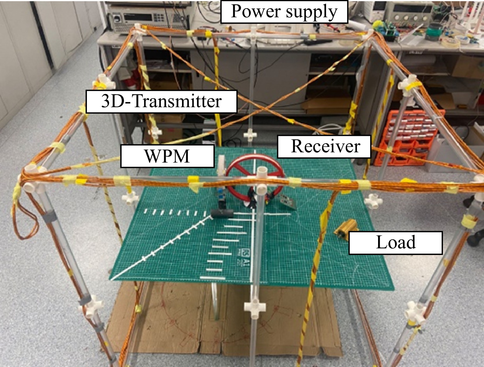
The photograph of the coil structure used in the experiment is shown in Fig. 6. Coil II was activated in this experiment. The transmitter coil, receiver coil, and WPM coil are tuned with capacitor series compensation. The receiver was fixed at the center. The main parameters of the system are listed in Table 1.
Table 1. Parameters for the WPT system in the experiment.
Parameters Value Operation frequency 100 kHz RMS value of the i1 3 A Size of the transmitter (length × width × high) 1 m × 1 m × 1 m Diameter of receiver 12.5 cm Turns of receiver 11 Diameter of WPM 10.5 cm Turns of WPM 11 Load 10 Ω Inductance of L1 156.6 μH Inductance of LM 47.4 μH Inductance of L2 64.5 μH ESR of L1 0.2 Ω ESR of LM 0.2 Ω ESR of L2 0.7 Ω The operating frequency of 100 kHz is commonly used in both academic and industry applications. This frequency typically does not interfere with other wireless communication devices (e.g., Wi-Fi, Bluetooth), which minimizes the impact on surrounding electronic equipment and offers an advantage in terms of electromagnetic compatibility. Additionally, on the one hand, the components, such as inverters and controllers for the 100 kHz systems are relatively inexpensive and readily available, making them suitable for the experiment. On the other hand, this frequency is followed by the Qi standard, which is widely used in real applications.
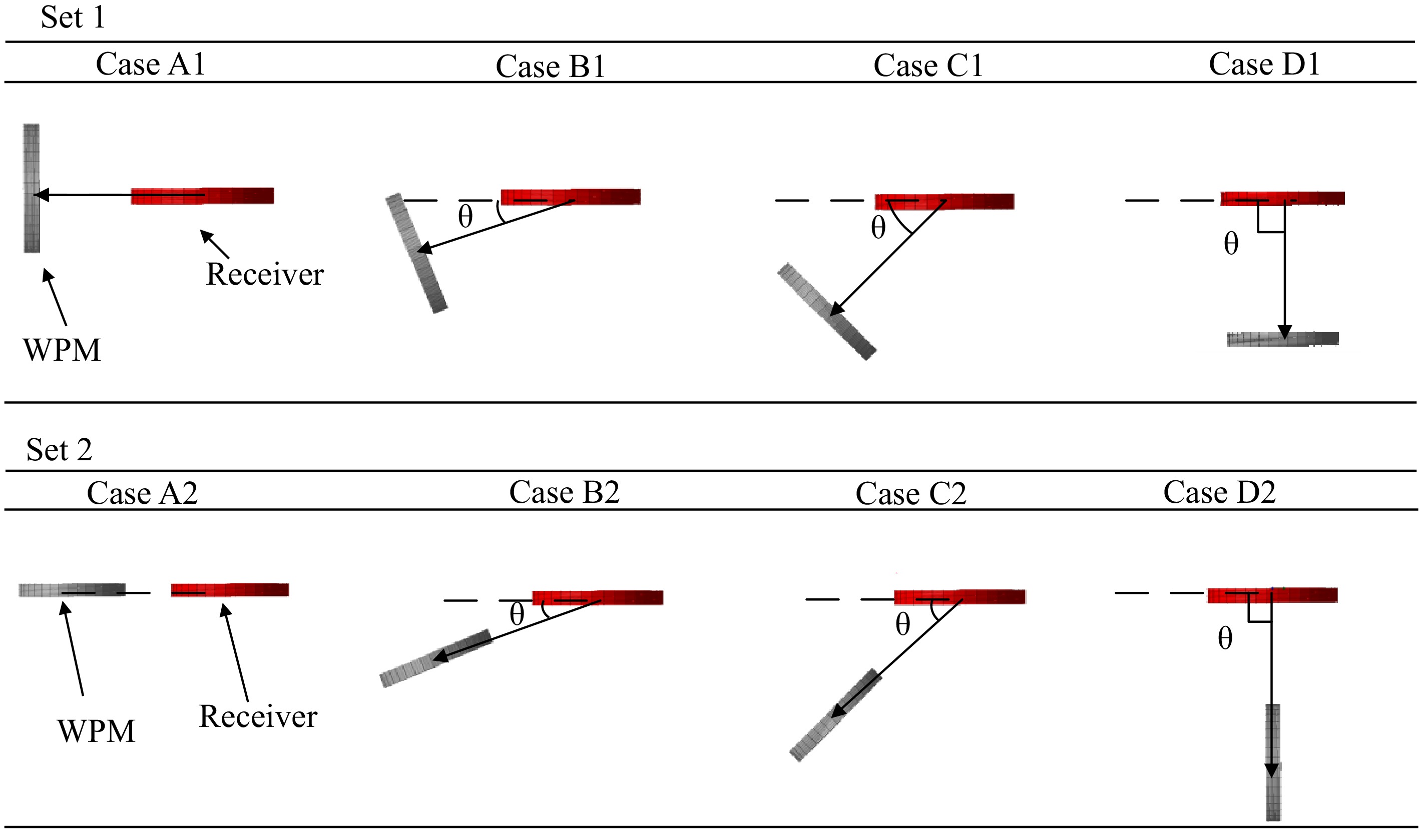
In the experiment, distance represents the length of the line connecting the center of the receiver and the center of the WPM. The diameter D of the receiver coil is used as the reference value for distance (per unit value*). The placement scheme of a WPM is designed in two sets, namely Set 1 and Set 2, as shown in Fig. 7. The main difference between the two sets is that the placement of the WPM of one set is orthogonal compared to the other set.
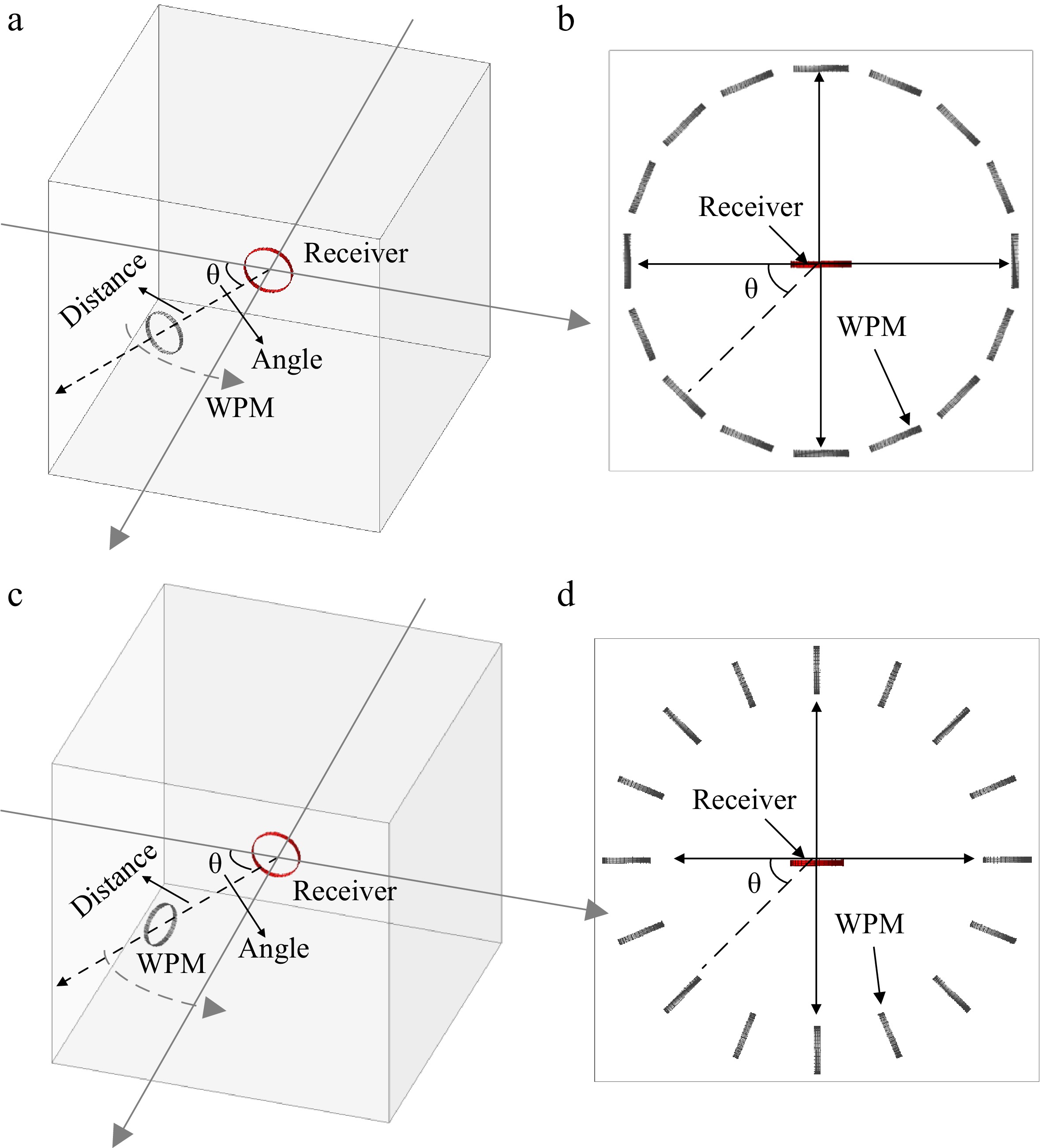
Figure 7.
Two different placement scheme designs for a WPM. (a) Set 1 (left) and its top view (right), (b) Set 2 (left) and its top view (right).
Since the magnetic flux inside the wireless charging container (as shown in Figs 3 & 4) is relatively weak at the center compared to the interior edges of the container, the receiver is fixed at that center to explore the effect of the WPM on the output power by different placement to improve the WPT system. The position of the WPM can be flexibly adjusted based on the practical location of the receiver. Additionally, the movement of the WPM provides a flexible way to regulate the output power.
The different placement angles of the WPM based on the angle between the receiver coil and the WPM are categorized into four cases. Due to the spatial symmetry of the magnetic field shown in Figs 3 & 4, four cases (i.e., Case A, Case B, Case C, and Case D) are executed in experiments A and B. The relative position between the WPM and receiver in these cases are illustrated in Fig. 8.
Results of Experiment A
-
In Experiment A, the resonant frequency for the transmitter, receiver, and WPM is set to the same as the operating frequency of 100 kHz. This section focuses on the effect of the placement of the WPM relative to the receiver in the container on output power. The power received by the receiver (power output to the load) when the WPM is not added to the wireless charging container is initially tested, and it is denoted as Pref = 2.35 W, which serves as a reference value in later experiments. As previously mentioned, the distance is represented by the nominal value (per unit*) of the diameter of the receiver coil (12.5 cm) as a base. The relationship between the power transferred to the load and the distance (*) is shown in Fig. 9 for each of the four different cases in Set 1 and Set 2.

Figure 9.
Variations of the output power to the distance for (a) cases of Set 1, and (b) cases of Set 2.
It can be observed from Fig. 9a that the placement design of WPM in Set 1 enhances the output power in most cases, surpassing the reference value. The findings for Fig. 9a can be summarized as follows:
(1) The results of the experiment show that when the two coils (receiver and WPM) are very close to each other and facing the same orientation, the output power is lower than the reference value (weakening effect).
(2) With the rotation angle increasing in Set 1, the output power increases. The maximum output is achieved in Case D (i.e., the WPM is coaxial with the receiver) with d* = 1.
It is worth emphasizing in particular that the optimal output power occurs when the two coils are at a distance of the receiver diameter (distance 1* in the figure) and the same orientation, not when they are close to each other and have the same orientation. As shown in Fig. 9b, the performance of Set 2 is opposite to Set 1, and the findings of Fig. 9b can be summarized as follows:
(1) In Set 2, the output power decreases as the angle and distance between the WPM and receiver vary. The most significant power drop occurs when the distance is equal to the receiver coil's diameter (d* = 1), as seen in cases B2 and C2.
(2) As the rotation angle increases in Set 2, the reduction in output power diminishes. Additionally, the placement of the WPM does not significantly affect the output power, as demonstrated in Case D of Set 2.
Results of Experiment B
-
In Experiment B, the self-resonant frequency (SRF) of the WPM is set differently from the operating frequency. The value of the SRF for the WPM is shown in Table 2.
Table 2. Setting of the self-resonance point of the WPM.
No. SRF of WPM (kHz) Deviation (kHz) 1 102.0 +2 kHz 2 101.2 +1.2 3 100.5 +0.5 4 100.0 0 (operation frequency) 5 99.5 −0.5 6 98.6 −1.4 7 97.9 −2.1 The output power can be regarded as a function of the distance (per unit) and SRF of the WPM. The relationship between the output power and the distance (per unit) under different SRFs is shown in Fig. 10.
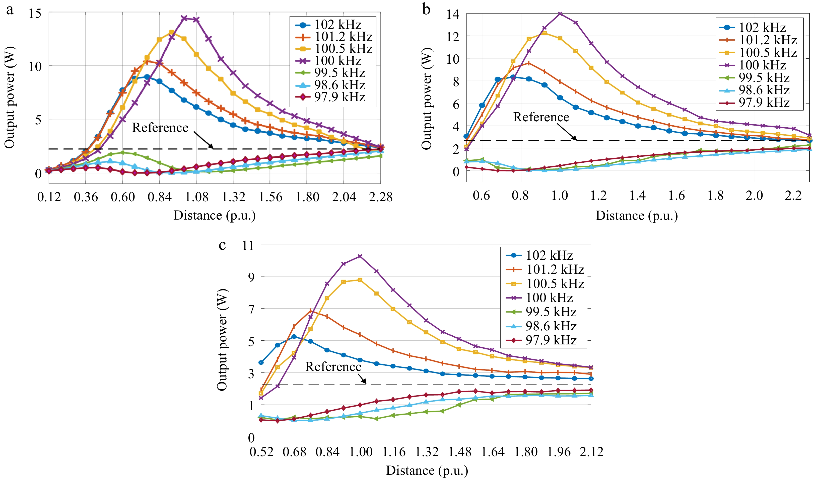
Figure 10.
Variations of output power with the distance (*) under the different SRFs for (a) Case D1, (b) Case C1, and (c) Case B1.
It can be seen from Fig. 10 that in Set 1, the WPM has a boosting effect on the output power when the SRF of the WPM is set in a nearby frequency range above the system's operating frequency (> 100 kHz). This power boost effect results in an optimal value at a certain distance, which is consistent with the conclusions of the previous section. It is also noted that this optimal power deviates from the nominal distance 1* (no longer the diameter of the receiver) because of the deviation in the SRF of the WPM.
Conversely, when the SRF of the WPM is set in a nearby frequency range below the system operating frequency (< 100 kHz), the WPM has a weakening effect on the output power. The optimal power weakening effect also does not occur at the distance 1*, which deviates with the SRF of the WPM.
The output power as a function of the distance (*) between the WPM and the receiver in different cases in Set 2 are shown in Fig. 11.
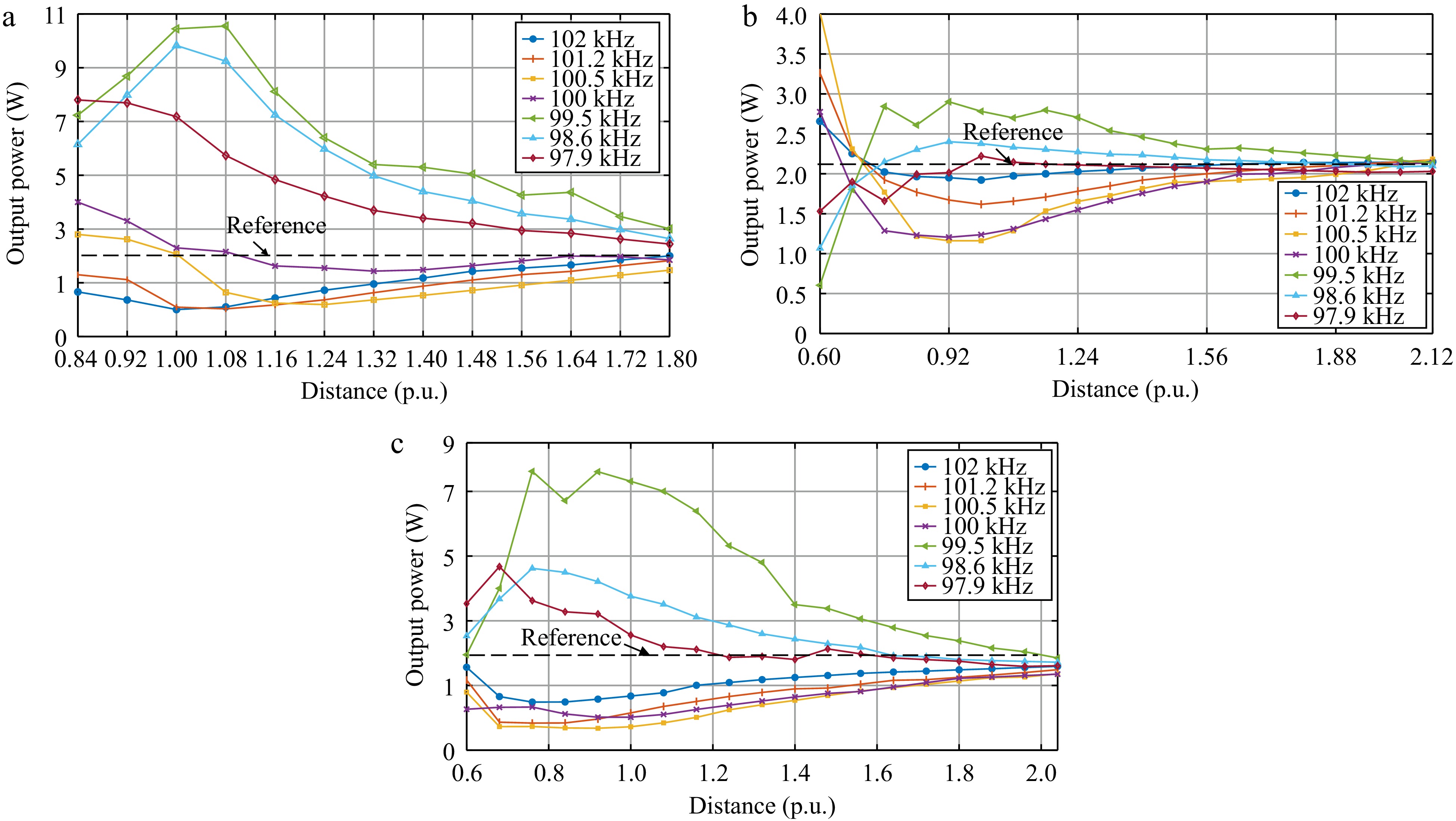
Figure 11.
Variations of output power with the distance (*) under the different SRFs for (a) Case A2, (b) Case B2, and (c) Case C2.
The results in Fig. 11 demonstrate that the designs in Set 2 and Set 1 has distinctly different effects on the output power. In Set 2, when the self-resonance point of the WPM is set at a frequency above the system operating frequency (> 100 kHz), the WPM functions as a power-boosting regulator. The optimal power boost effect shifts with changes in the WPM's self-resonance frequency.
Conversely, in Set 1, when the self-resonance point of the WPM is set below the system operating frequency (< 100 kHz), the WPM acts as a power-weakening regulator. The location of the optimal power-weakening effect shifts with deviations in the WPM's self-resonance frequency. The overall trend of the SRF of the WPM for the designs of Set 1 and Set 2 with respect to the output power is summarized in Fig. 12.

Figure 12.
Effects of the self-resonance points deviation of the WPM and output power (a) Set 1, and (b) Set 2.
Based on the experimental results and analysis, the output power of the receiver can be modulated using the WPM in this wireless charging container. When the frequency of the WPM is set slightly higher than the operating frequency and aligned with the placement orientation of Set 1, a power enhancement effect can be obtained. Conversely, when the frequency of the WPM is set slightly lower than the operating frequency and is placed at a distance equal to the receiver diameter as indicated by the placement orientation of Set 2, a power weakening effect can be achieved.
-
This paper presents a power modulation design for a cubic wireless charging container configured with a WPM. The management of the power flow can be realized in two ways, i.e., regulating the position and SRF of the WPM. Based on the two designs, two sets of WPM placement schemes are proposed. The results show that the WPM can have both enhancing and weakening effects on the output power of the receiver, which is a guiding significance for the application of WPM in practical power flow regulation.
The authors are thankful for the financial support from the Ministry of Education (MoE) Academic Research Fund (AcRF) Tier-1 RG134/23 and the A*Star MTC Young Individual Research Grant (YIRG) M23M7c0115.
-
The authors confirm contribution to the paper as follows: conceptualization: Yang Y, Yang J; data curation, formal analysis, methodology, visualization: Shang S, Tang K; funding acquisition: Yang Y; investigation: Shang S, Wang K, Tang K; project administration: Yang Y, Wang K, Liang R; resources: Yang Y, Liang R, Yang J; software, validation: Shang S, Wang K, Liang R, Tang K; writing - original draft: Shang S; supervision, writing - review & editing: Wang K, Yang Y. All authors reviewed the results and approved the final version of the manuscript.
-
The data that support the findings of this study are available from the corresponding author upon reasonable request.
-
The authors declare that they have no conflict of interest. Yun Yang is the Editorial Board member of Wireless Power Transfer who was blinded from reviewing or making decisions on the manuscript. The article was subject to the journal's standard procedures, with peer-review handled independently of this Editorial Board member and the research groups.
- Copyright: © 2024 by the author(s). Published by Maximum Academic Press, Fayetteville, GA. This article is an open access article distributed under Creative Commons Attribution License (CC BY 4.0), visit https://creativecommons.org/licenses/by/4.0/.
-
About this article
Cite this article
Shang S, Wang K, Liang R, Tang K, Yang J, et al. 2024. Investigations on the use of a wireless power modulator in a wireless charging container. Wireless Power Transfer 11: e010 doi: 10.48130/wpt-0024-0010
Investigations on the use of a wireless power modulator in a wireless charging container
- Received: 11 March 2024
- Revised: 21 May 2024
- Accepted: 06 September 2024
- Published online: 05 November 2024
Abstract: This paper analyzes the use of a wireless power modulator (WPM) in a cubic wireless charging container. The relay coil acts as a WPM capable of boosting or decreasing the output power. By designing the self-resonant frequency and the relative position of the WPM, different power flow regulations can be realized. The experiment is carried out on a cubic wireless charging container with a diameter of 1 m to verify the effects of the WPM.
-
Key words:
- Wireless power modulator /
- Wireless charging container /
- Relay coils


