-
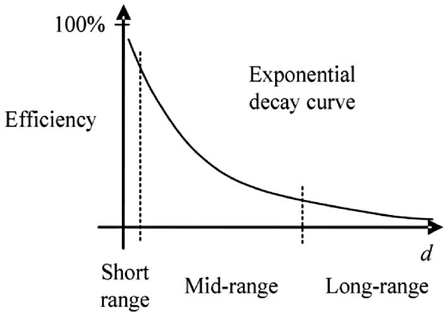
Figure 1.
Exponential decay curve of the efficiency as a function of transmission distance d for a two-stage IPT system[4].
-
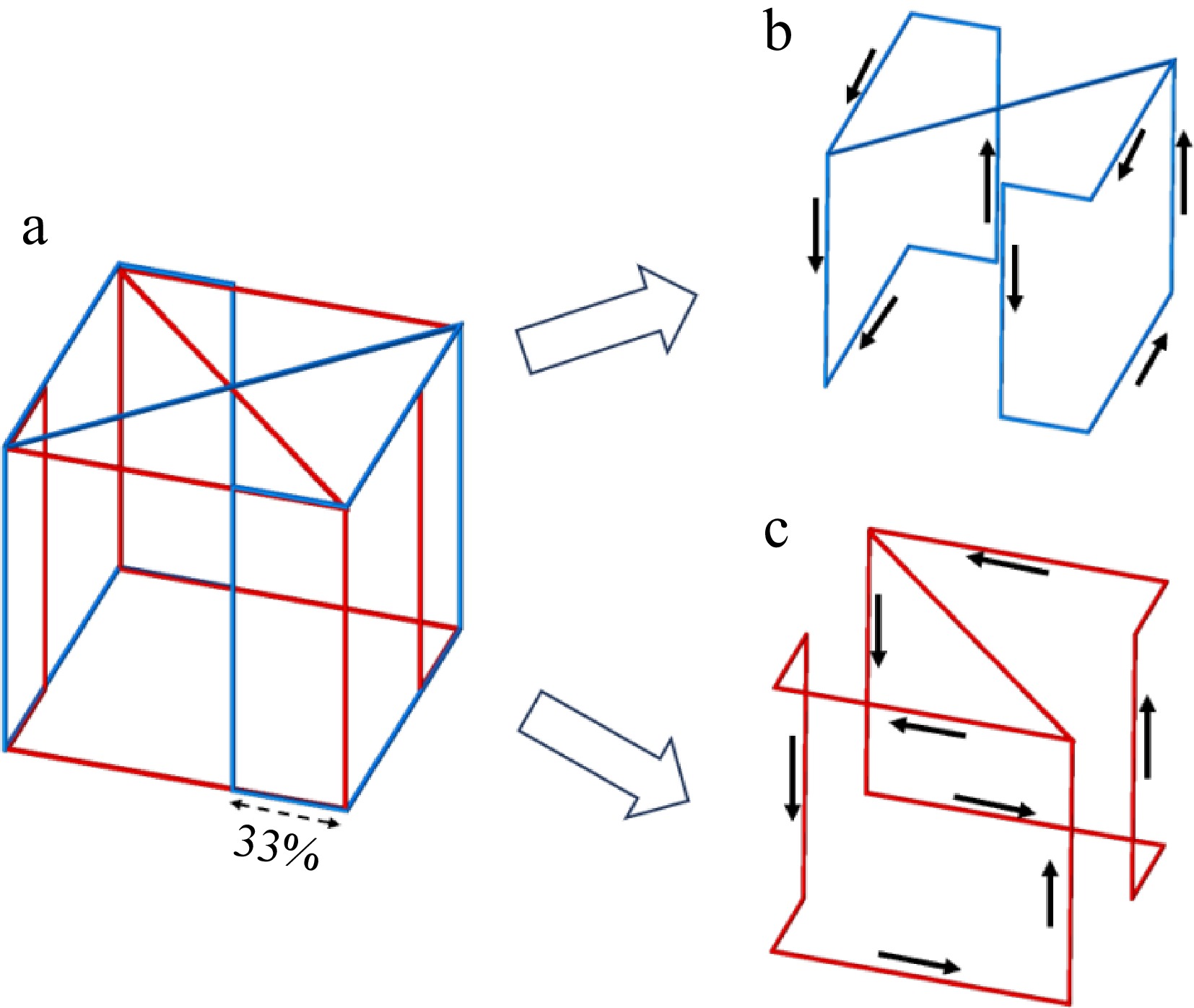
Figure 2.
Coil winding and current flow profile of the container. (a) WPT system for wireless charging incubator configured with a WPM, (b) Coil I in transmitter, (c) Coil II in transmitter.
-
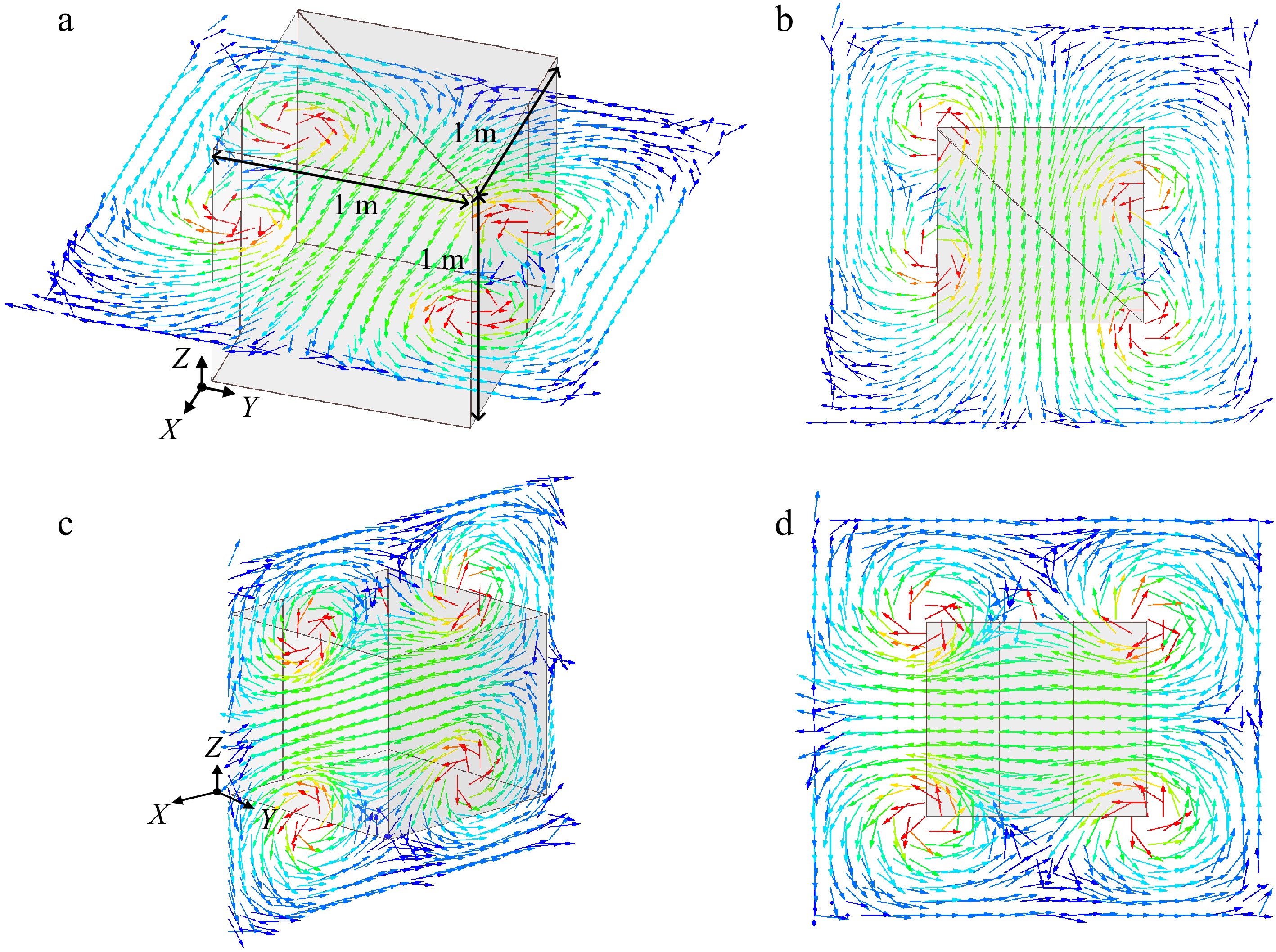
Figure 3.
Magnetic flux distribution inside the wireless charging container for one coil (Coil II for example) operation. (a) Horizontal plane, (b) top view of magnetic flux distribution, (c) vertical plane, (d) side view of magnetic flux distribution.
-
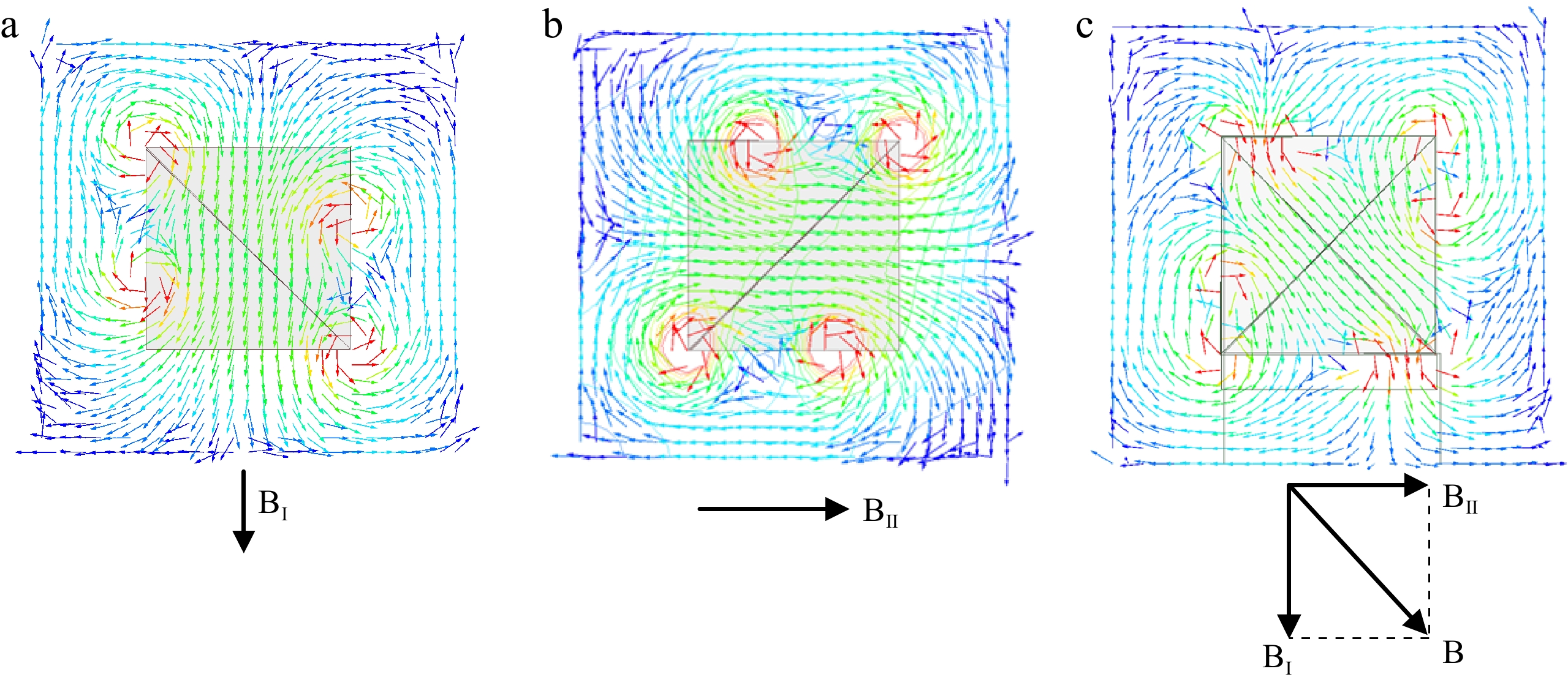
Figure 4.
Top view of magnetic flux distribution when different coils operating and their relationship. (a) Coil I operating, (b) Coil II operating, (c) Coil I and Coil II operating.
-
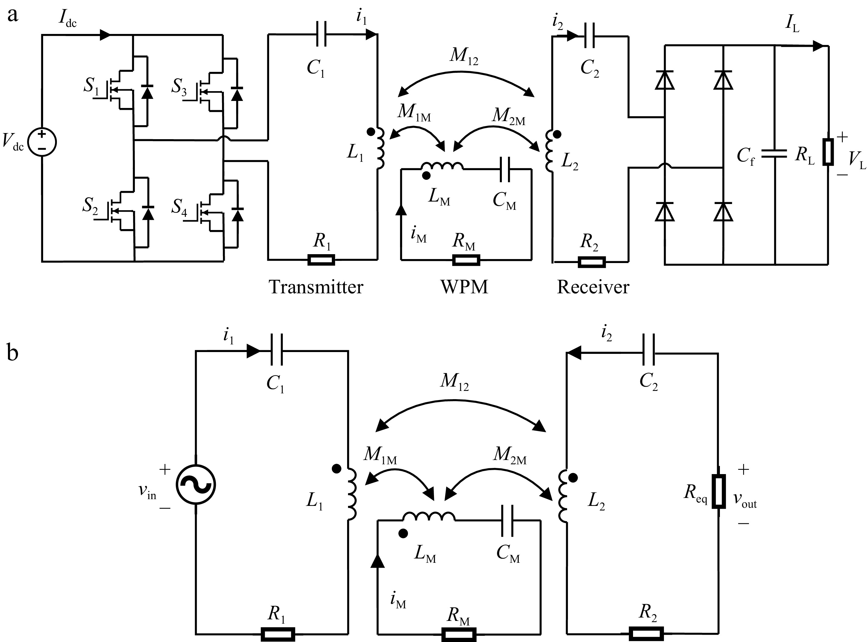
Figure 5.
(a) Equivalent circuit model for the proposed WPT system, and (b) the simplified circuit model.
-
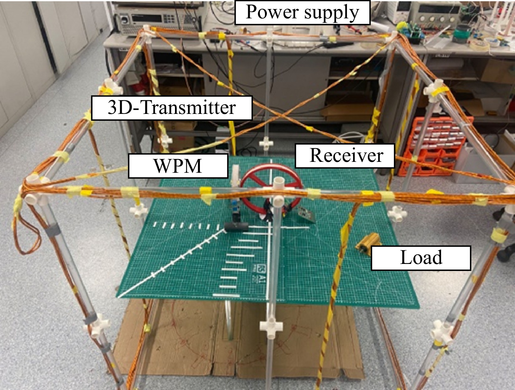
Figure 6.
Photograph of the experimental setup.
-
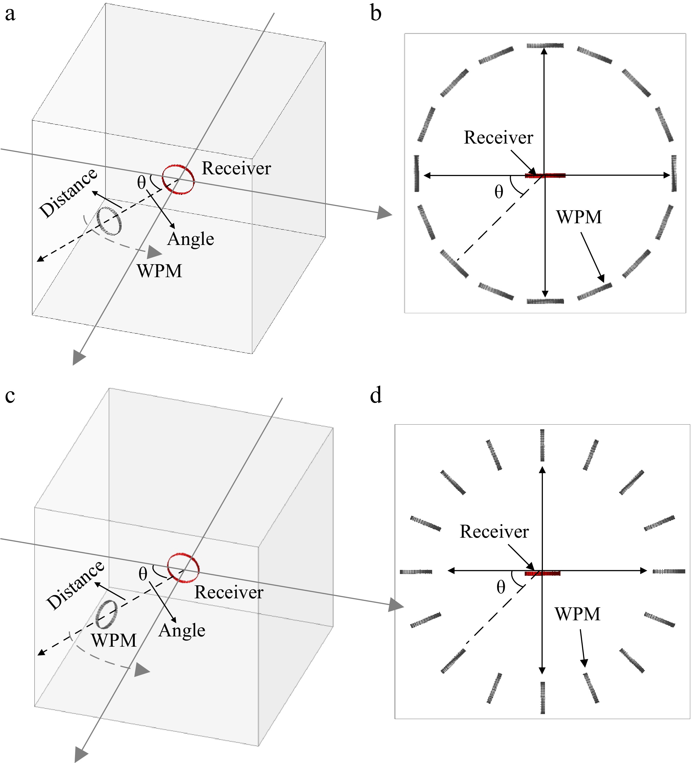
Figure 7.
Two different placement scheme designs for a WPM. (a) Set 1 (left) and its top view (right), (b) Set 2 (left) and its top view (right).
-

Figure 9.
Variations of the output power to the distance for (a) cases of Set 1, and (b) cases of Set 2.
-
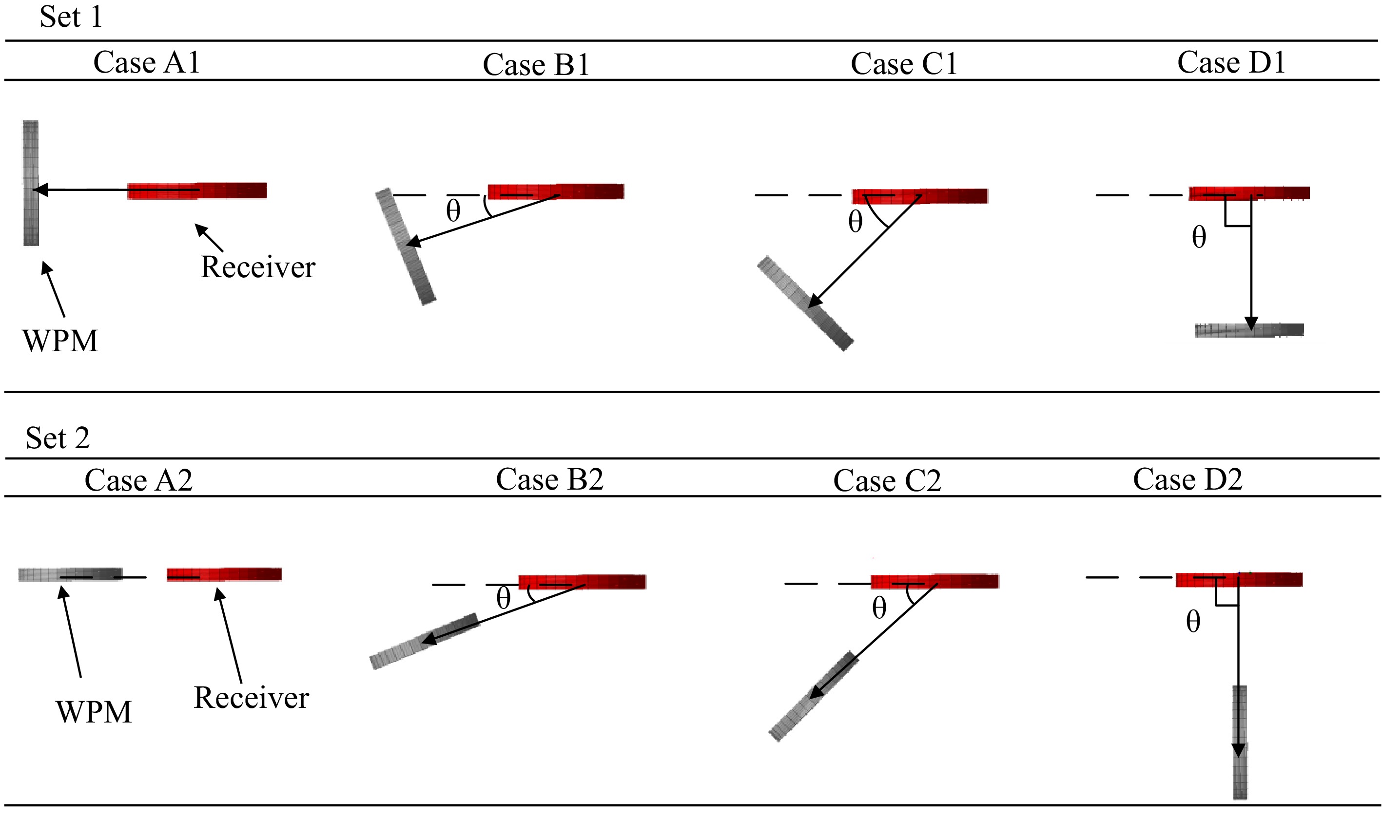
Figure 8.
Placement cases of WPM in Set 1 and Set 2.
-
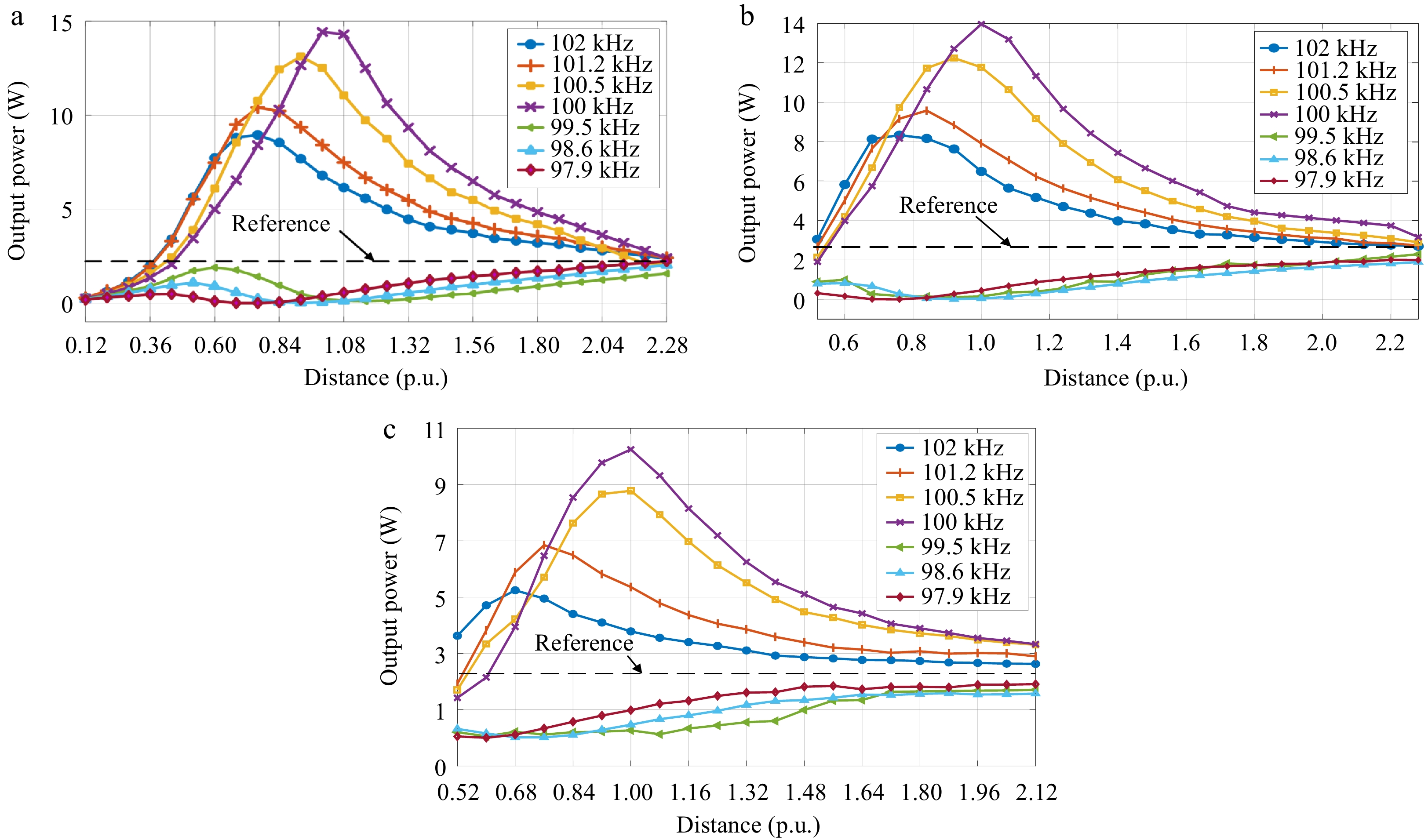
Figure 10.
Variations of output power with the distance (*) under the different SRFs for (a) Case D1, (b) Case C1, and (c) Case B1.
-
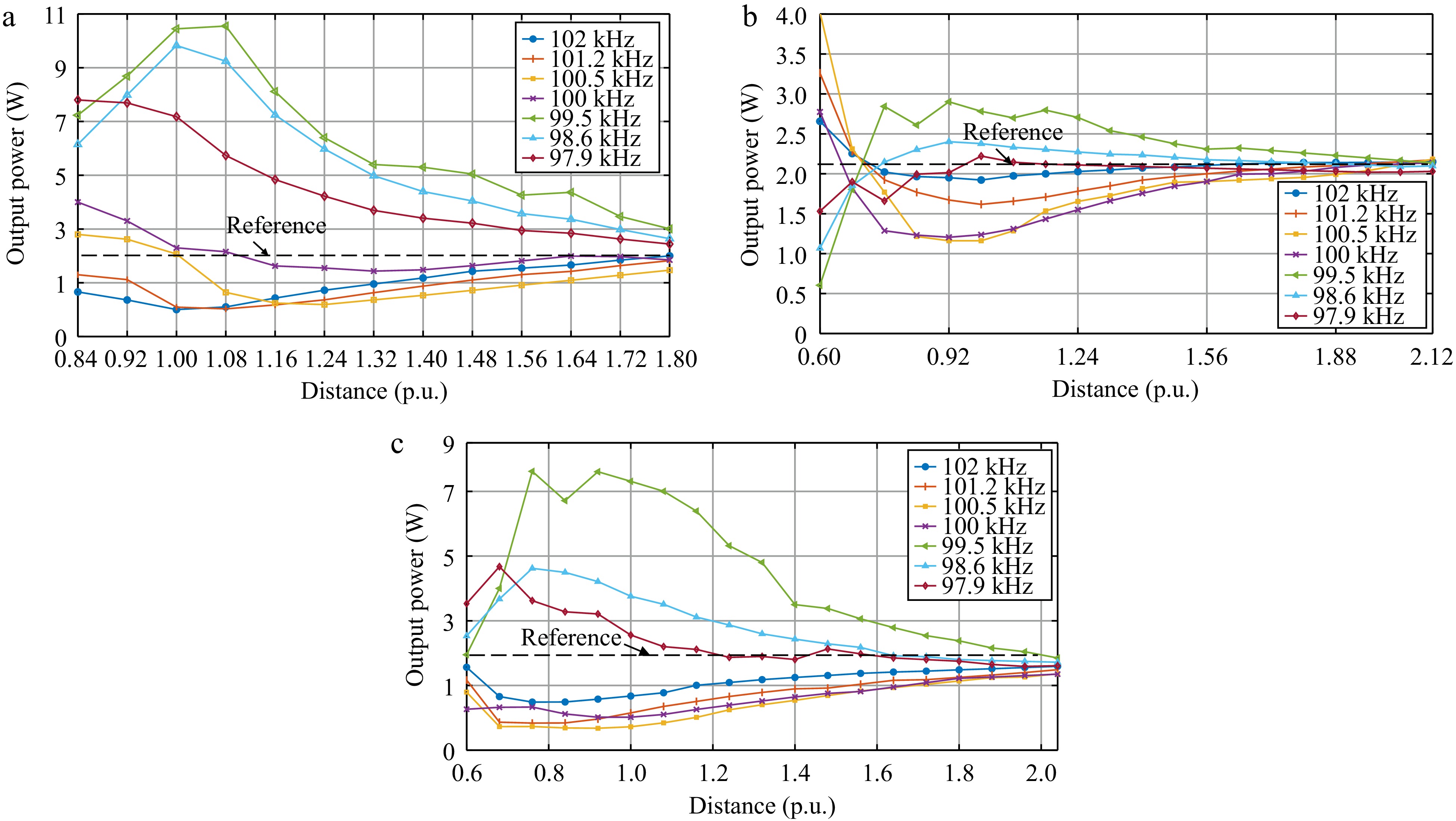
Figure 11.
Variations of output power with the distance (*) under the different SRFs for (a) Case A2, (b) Case B2, and (c) Case C2.
-

Figure 12.
Effects of the self-resonance points deviation of the WPM and output power (a) Set 1, and (b) Set 2.
-
Parameters Value Operation frequency 100 kHz RMS value of the i1 3 A Size of the transmitter (length × width × high) 1 m × 1 m × 1 m Diameter of receiver 12.5 cm Turns of receiver 11 Diameter of WPM 10.5 cm Turns of WPM 11 Load 10 Ω Inductance of L1 156.6 μH Inductance of LM 47.4 μH Inductance of L2 64.5 μH ESR of L1 0.2 Ω ESR of LM 0.2 Ω ESR of L2 0.7 Ω Table 1.
Parameters for the WPT system in the experiment.
-
No. SRF of WPM (kHz) Deviation (kHz) 1 102.0 +2 kHz 2 101.2 +1.2 3 100.5 +0.5 4 100.0 0 (operation frequency) 5 99.5 −0.5 6 98.6 −1.4 7 97.9 −2.1 Table 2.
Setting of the self-resonance point of the WPM.
Figures
(12)
Tables
(2)