ARTICLE   Open Access    

Investigations on the use of a wireless power modulator in a wireless charging container

More Information
  • This paper analyzes the use of a wireless power modulator (WPM) in a cubic wireless charging container. The relay coil acts as a WPM capable of boosting or decreasing the output power. By designing the self-resonant frequency and the relative position of the WPM, different power flow regulations can be realized. The experiment is carried out on a cubic wireless charging container with a diameter of 1 m to verify the effects of the WPM.
  • The tea plant (Camellia sinensis) was first discovered and utilized in China, where its tender leaves were processed into tea. Tea has become the second most popular beverage after water worldwide. Tea contains tea polyphenols, amino acids, vitamins, lipopolysaccharides and other nutrients, as well as potassium, calcium, magnesium, iron, fluorine and other trace elements, which have antioxidant, lipid-lowering, hypoglycaemic, anti-caries, enhance the body's immunity and other physiological regulatory functions[1]. Among them, fluorine is an element widely found in the earth's crust, mainly in the form of fluoride in the environment, is one of the essential trace elements for human beings, and is vital to the growth and development of human bones and teeth[2]. When the human body takes in an appropriate amount of fluorine, it can effectively prevent the formation of dental caries, enhance the absorption of calcium, phosphorus and other elements of the human body. Excessive intake of fluorine however will lead to chronic cumulative poisoning, damaged bone tissue, affect the function of various tissues and organs in the body, and cause harm to health[3]. Tea plants can absorb and accumulate fluoride from air, water and soil, mainly concentrated in the leaves, most of the fluoride in the leaves can be released into the tea soup and be absorbed by the human body, so the fluoride content in tea is closely related to human health[4]. Generally speaking, green tea, black tea, white tea, oolong tea and yellow tea are made from the young buds and shoots of the tea plant, and their fluorine content is low. Some dark tea made from leaves with lower maturity has lower fluorine content. However, the dark tea made from leaves with higher maturity has a high fluorine content, and therefore poses a risk of excessive fluorine[5]. Long-term drinking of dark tea with excessive fluorine content is a cause of tea-drinking fluorosis[6].

    Dark tea, with its smooth taste and digestive benefits, became an indispensable drink in the lives of the Chinese herders, who were mainly meat eaters[7]. Dark tea has also gained popularity in the wider population because of its important health-promoting effects, such as prevention of cardiovascular and cerebrovascular diseases, lowering blood pressure, and promoting weight loss and fat reduction[8]. Long-term consumption of dark tea is likely to cause fluorosis for two reasons: 1) Chinese border ethnic minorities generally use the boiling method to brew dark tea, which increases the leaching rate of fluoride[9] and leads to high fluoride levels in the human body; 2) most of the fresh tea leaves utilized to make dark tea are older and more mature leaves, which contain higher levels of fluoride than younger leaves[10]. The mature leaves of tea plants accumulate a large amount of fluoride, but can grow normally without fluoride poisoning, indicating that tea plants are able to accumulate and tolerate fluoride. Due to the problem of tea-drinking fluorosis, the excessive accumulation of fluoride in tea plants has attracted widespread attention[10]. It is important to investigate the mechanisms related to fluoride absorption, transportation, enrichment, and tolerance in tea plants to develop effective and practical management and control programs to reduce the fluoride content in tea and ensure its safety. Recent research on defluorination measures for tea has included preliminary screening of tea germplasm resources, management measures during tea plant cultivation, processing technologies, and tea brewing methods. In this review, we summarize the results of studies on how fluoride moves from the environment into tea plants and the factors affecting this process, how fluoride is transported in tea plants, the mechanisms of fluoride tolerance in tea plants, and current measures to reduce the fluoride content in tea.

    Tea plants are fluoride-accumulators with the ability to absorb and accumulate fluoride from the surrounding environment. The fluoride content in tea plants is significantly higher than that of other plants under similar growth conditions[11]. After fluoride is absorbed by the roots of tea plants, it is transferred to the above-ground parts, and is also transferred from the leaves downward (Fig. 1), but not from the above-ground parts to the below-ground parts (Fig. 2). External factors such as atmospheric, soil, and water conditions around the tea plant and internal factors can affect the fluoride content in different plant tissues.

    Figure 1.  Fluoride absorption by tea plants. Tea plants absorb fluoride from the atmosphere, soil, and water. Fluoride in the atmosphere is absorbed through the stomata or cuticle of the leaf epidermis. Fluoride ions and fluoride–aluminum complexes in soil and water are absorbed by the roots.
    Figure 2.  Fluoride transportation in tea plants. Fluoride absorbed by the leaves is transferred to the leaf tips and edges, chelates with metal ions, and the complexes are deposited in the leaves. Fluoride can be transferred from old leaves to new tips. Fluoride from soil and water can form complexes with organic acids and aluminum, which are stored in the leaves of tea plants. Fluoride from soil and water can also be individually absorbed and transported for storage in the leaves.

    Fluoride occurs in many forms in nature. Fluoride in the atmosphere mainly exists in the form of hydrogen fluoride, and that in the soil mainly exists in three forms: insoluble, exchangeable, and water-soluble fluoride. Atmospheric fluoride is mainly absorbed through the stomata of tea plant leaves or the cuticle of the epidermis, and its concentration is relatively low[12]. Insoluble fluoride and exchangeable fluoride in the soil cannot be absorbed by tea plants. Water-soluble fluoride is the main form absorbed by the root system of tea plants[13]. Several studies have detected a significant positive correlation between the fluoride content in tea and the water-soluble fluoride content in soil[14,15]. Water-soluble fluoride mainly refers to the fluoride ion (F) or fluoride complexes in soil and water solutions, including free F and fluoride complexed with ions. The water-soluble state has the strongest activity and the highest biological availability, so it is conducive to the migration of fluoride in the environment[16].

    The root system is the main organ responsible for fluoride absorption in tea plants. Water-soluble fluoride can enter the root system by passive or active absorption, depending on its concentration. Fluoride at lower concentrations in solution (0.1–10 mg/L) is mainly absorbed and enriched in the root system of tea plants via active absorption, with a kinetic curve following the Michalis–Menten kinetic model. At higher concentrations (50–100 mg/L), water-soluble fluoride is absorbed at a rate that increases with increasing concentration, and this is achieved via passive absorption[17]. Many studies have shown that the water-soluble fluoride content in soils in most tea-producing regions in China is below the threshold for passive absorption[1820], indicating that fluoride mainly enters tea plants via active absorption by the roots.

    The active uptake of fluoride by tea roots is mediated by ion pump carrier proteins and ABC transporter proteins. Ion pump carrier proteins can transport the substrate across the cell membrane against the electrochemical gradient, and use the energy of ATP hydrolysis to participate in the process of active transport of substances, mainly including proton pump H+-ATPase and calcium ion pump Ca2+-ATPase. ABC transporter proteins can transport ions or heavy metals to vesicles as chelated peptide complexes, thereby reducing toxicity to the cell and improving plant resistance to abiotic stress. Passive fluoride absorption by the root system of tea plants involves water channels and ion channels. Studies on the effects of applying external anion channel inhibitors, cation channel inhibitors, and water channel inhibitors showed that inhibition of external anion channels significantly reduced the absorption of fluoride by roots. This indicated that anion channels are an important pathway for the uptake and trans-membrane transport of fluoride in the root system of tea plants[17,21,22]. The homeostatic flow of ions through channels diffusing along a trans-membrane concentration gradient or potential gradient involves ion channel proteins[23]. Two phylogenetically independent ion channel proteins have recently been identified in tea plants: CLCF-type F/H+ reverse transporter proteins and the FEX (Fluoride export gene) family of small membrane proteins[24]. CLC proteins are involved in the transport of a variety of anions such as chlorine (Cl) and F into and out of the cell. The FEX proteins in tea plants are involved in fluoride absorption via thermodynamic passive electro-diffusion through transmembrane channels[25,26].

    After fluoride is absorbed, it is transported within the tea plant by several different pathways. These include transport after leaf absorption, transport after root absorption, and transfer inside tea plant cells. The fluoride absorbed by leaves can be transferred along the conduit to the leaf tips and edges, accumulating in the top and ipsilateral leaves, but not in the roots. Fluoride in the soil and water environment is taken up by the root system and transported to the xylem via intracellular and intercellular transport. It is then transported upwards via transpiration and eventually accumulates in the leaves[27,28]. Two transport mechanisms have been proposed for the translocation of fluoride via the xylem. One proposed mechanism is that it is translocated in the form of fluoride-aluminum complexes[29]. The other proposed mechanism is that aluminum and fluoride are transported separately and accumulate after reaching the leaves[30].

    The roots are the main organ responsible for fluoride absorption in tea plants. Therefore, most studies have focused on the transport process in roots, especially the transport of fluoride by fluoride-related transporters. It has been found that under acidic conditions, F preferentially forms complexes with Al3+ and these complexes are then absorbed by roots and transported upward in the same state[29,31]. Studies have shown that, compared with F, aluminum-fluoride complexes are more easily absorbed and transported to the new shoots by the root system. This may be related to the elimination of the separate toxic effects of F and Al3+ [29]. Fluoride can also be transported in tea plants by binding to aluminum-organic acid complexes, and then accumulate in the leaves[29]. Both tea plant fluoride transporter proteins, CsFEX1 and CsFEX2, are involved in fluoride transport, but their encoding genes can be differentially expressed among different varieties and depending on the concentration of fluoride. In one study, the expression level of CsFEX1 was consistent among different varieties, while the expression of CsFEX2 was induced under fluoride stress to increase fluoride efflux from tea plants, thereby reducing its accumulation in low-fluoride varieties[32]. In addition, the A–G subfamily of ABC transporters plays a carrier role in the transmembrane transport of F- and Cl- in tea plants[33]. It was found that the expression of the ABC transporter protein CsCL667 was up-regulated in response to fluoride treatment, and its ability to transport fluoride was enhanced, suggesting that CsCL667 functions in fluoride efflux[34]. Another study demonstrated that CsABCB9 localizes in chloroplasts and functions as a fluoride efflux transporter to reduce fluoride-induced damage in leaves and enhance chloroplast activity[35].

    Several factors affect the absorption and transport of fluoride in tea plants, including the absorbable fluoride concentration, soil pH, the presence of other ions, and the activity of ion channels[3638]. Fluoride in nature is present in the atmosphere and soil, and its concentration is the main factor affecting the fluoride content in tea plants. Under normal conditions, tea plants generally absorb fluoride from the soil through the roots, but when the hydrogen fluoride content in the atmosphere is high, tea plants can absorb it through the leaves. The fluoride content in tea plants growing in the same geographical area is similar, mainly because of the soil properties in that area. Tea plants grow in acidic environments, and fluoride in acidic soils is more easily absorbed. During the growth of tea plants, the roots secrete organic acids such as oxalic acid, citric acid, and malic acid, which promote the absorption of fluoride by the roots and its transport to above-ground parts[39]. Other ions such as Ca2+ and Mg2+ combine with F to form precipitates, resulting in lower concentrations of water-soluble fluoride in the soil, which also affects its absorption by tea plant roots[40]. Exogenously applied calcium at low concentrations can change the cell wall structure and membrane permeability in tea plant roots, ultimately leading to reduced fluoride content in tea leaves[36,41,42]. Meanwhile, Al3+ treatment can trigger Ca2+ signaling in tea plant roots, which in turn activates calmodulin and promotes fluoride absorption[43]. The H+ gradient generated by the plasma membrane H+-ATPase can also promote Ca2+ signaling in plants to regulate the transmembrane transport of ions, which affects fluoride absorption[43]. The abundance and activity of H+-ATPase in the plasma membrane of tea plant roots have been found to increase significantly under fluoride stress, and these increases result in improved absorption of fluoride, although this is also affected by the fluoride concentration and temperature[33]. Sodium fluoride was found to induce the expression of genes encoding ABC transporter proteins, resulting in the transmembrane absorption of large amounts of fluoride ions into cells[34]. ABC transporters also transport ions alone or in the form of chelated peptide complexes directly out of the cellular membrane, which improves cellular tolerance to these ions[44]. Some anions with the same valence state also affect the F content in tea plants. For example, the ion channel protein encoded by CLCF is more sensitive to F, more selective for F than for Cl, and functions to export F from the cytoplasm to protect against fluorosis[4547].

    It can be seen that reducing the absorption of fluorine by tea plants and changing the mechanism of fluorine transportation in tea plants can reduce the content of fluorine in different parts of the tea plants. From the mechanism of fluorine absorption, the most effective way is to directly change the form of soil fluorine to reduce the absorption of water-soluble fluorine by roots. On this basis, it is possible to further change the active absorption process of fluorine mediated by ion pump carrier protein and ABC transporter protein in tea roots by molecular techniques. From the perspective of fluorine transport mechanism, the toxic effect of fluorine on tea plants can be reduced mainly by promoting the function of transporter proteins to exclude fluorine from the cell or transport it to the vesicle. The comprehensive application of the above methods to limit fluorine absorption and promote fluorine transport in tea plants can limit the accumulation of fluorine in tea plants.

    The fluoride enrichment characteristics of tea plants are related to various factors, including the tea variety, the organ, and the season. Among different varieties of tea, differences in leaf structure and other physiological characteristics can lead to variations in fluoride absorption and enrichment[48]. Some studies have concluded that the variety is one of the main determinants of the fluoride content in tea leaves[10], and the differences in fluoride content among most varieties reached highly significant levels (Table 1), which can be divided into low-enriched, medium-enriched, and high-enriched germplasm[49]. Various organs of tea plants also show differences in fluoride accumulation. The fluoride content is much higher in leaves than in roots and stems, and significantly higher in old leaves than in new shoots[10,50,51]. The fluoride content can differ widely among tea plants at different developmental stages. In spring, the new leaves begin to accumulate fluoride from the environment, and the fluoride content increases as the leaves age. When the growth rate of tea leaves is slower, they absorb and accumulate more fluoride from the soil and air. When the temperature in summer and autumn is high, the growth rate of tea leaves is fast and the growth period is short, so less fluoride is absorbed and accumulated from the soil and air. This explains why the fluoride content in fresh tea leaves was higher in spring and relatively lower in summer and autumn[4]. Another study found that, in China, the fluoride content in tea leaves was higher in summer than in spring. This may have been related to the maturity level of the tea leaves at harvest and different patterns of fluoride transport[4].

    Table 1.  Fluoride content difference of different tea cultivars.
    Cultivars Province Parts Treatment Years Content (mg/kg) Ref.
    Liannandaye Sichuan Old leaves Drying at 80 °C and boiling water extraction 2006−2007 1,150.79 ± 4.86 [107]
    Mature leaves Drying at 70 °C and hydrochloric acid extraction 2006 1,296.66 ± 12.84 [110]
    Yuenandaye Old leaves Drying at 80 °C and boiling water extraction 2006−2007 1,352.89 ± 12.69 [107]
    Mature leaves Drying at 70 °C and hydrochloric acid extraction 2006 1,560.36 ± 27.10 [110]
    Chenxi NO.4 Old leaves Drying at 80 °C and boiling water extraction 2006−2007 1,865.61 ± 7.46 [107]
    Mature leaves Drying at 70 °C and hydrochloric acid extraction 2006 1,954.93 ± 10.96 [110]
    Meizhan Old leaves Drying at 80 °C and boiling water extraction 2006−2007 2,180.13 ± 14.42 [107]
    Mature leaves Drying at 70 °C and hydrochloric acid extraction 2006 1,732.2 ± 41.2 [110]
    Zhejiang Mature leaves Drying at 80 °C and nitric acid extraction 2002 2,015.48 ± 29.99 [106]
    Fudingdabai Sichuan Old leaves Drying at 80 °C and boiling water extraction 2006−2007 249.64 ± 24.3 [107]
    Guizhou One bud and
    five leaves
    Drying at 80 °C and hydrochloric acid extraction 2010 1,612.3 ± 43.1 [109]
    Fudingdabai Zhejiang Mature leaves Drying at 80 °C and nitric acid extraction 2002 137.1 ± 2.1 [106]
    Fujian Old leaves Drying at 80 °C and hydrochloric acid extraction 2010 282.1 [111]
    Hunan One bud and
    five leaves
    Steaming and boiling water extraction 2011 2,232.05 ± 85.52 [51]
    Zhuyeqi Ya'an and
    surroundings
    Old leaves Drying at 80 °C and boiling water extraction 2006−2007 2,750.16 ± 11.37 [107]
    Ya'an Mature leaves Drying at 70 °C and hydrochloric acid extraction 2006 125.4 [110]
    Hunan One bud and
    five leaves
    Steaming and boiling water extraction 2011 2,330.74 ± 31.39 [51]
    Fujianshuixian Ya'an and
    surroundings
    Old leaves Drying at 80 °C and boiling water extraction 2006−2007 2,548.18 ± 40.97 [107]
    Ya'an Mature leaves Drying at 70 °C and hydrochloric acid extraction 2006 103.7 ± 1.5 [110]
    Fujian Old leaves Drying at 80 °C and hydrochloric acid extraction 2010 1,150.79 ± 4.86 [111]
    Huangyeshuixian Ya'an and
    surroundings
    Old leaves Drying at 80 °C and boiling water extraction 2006−2007 2,424.70 ± 18.85 [107]
    Ya'an Mature leaves Drying at 70 °C and hydrochloric acid extraction 2006 2,950.80 ± 27.73 [110]
    Qianmei 701 Ya'an and
    surroundings
    Old leaves Drying at 80 °C and boiling water extraction 2006−2007 2,522.01 ± 45.33 [107]
    Ya'an Mature leaves Drying at 70 °C and hydrochloric acid extraction 2006 3,693.09 ± 35.12 [110]
    Guizhou One bud and
    five leaves
    Drying at 80 °C and hydrochloric acid extraction 2010 389.95 ± 32.18 [109]
    Guizhou Old leaves Dry samples and hydrochloric acid extraction 2011 2,142.26 ± 16.30 [113]
    Mingshan 130 Ya'an and
    surroundings
    Old leaves Drying at 80 °C and boiling water extraction 2006−2007 2,564.78 ± 51.22 [107]
    Ya'an Mature leaves Drying at 70 °C and hydrochloric acid extraction 2006 3,036.13 ± 31.25 [110]
    Mengshan 9 Ya'an and
    surroundings
    Old leaves Drying at 80 °C and boiling water extraction 2006−2007 2,647.31 ± 70.89 [107]
    Ya'an Mature leaves Drying at 70 °C and hydrochloric acid extraction 2006 3,436.55 ± 20.21 [110]
    Yinghong NO. 2 Ya'an and
    surroundings
    Old leaves Drying at 80 °C and boiling water extraction 2006−2007 2,669.02 ± 799.95 [107]
    Ya'an Mature leaves Drying at 70 °C and hydrochloric acid extraction 2006 3,364.53 ± 51.72 [110]
    Mengshan 11 Ya'an and
    surroundings
    Old leaves Drying at 80 °C and boiling water extraction 2006−2007 2,695.21 ± 59.89 [107]
    Ya'an Mature leaves Drying at 70 °C and hydrochloric acid extraction 2006 3,582.83 ± 9.73 [110]
    Mingshan 311 Ya'an and
    surroundings
    Old leaves Drying at 80 °C and boiling water extraction 2006−2007 2,716.22 ± 42.21 [107]
    Donghuzao 2,731.20 ± 20.78
    Ya'an Mature leaves Drying at 70 °C and hydrochloric acid extraction 2006 3,107.27 ± 54.91 [110]
    Hainandaye Ya'an and
    surroundings
    Old leaves Drying at 80 °C and boiling water extraction 2006−2007 2,746.82 ± 39.71 [107]
    Ya'an Mature leaves Drying at 70 °C and hydrochloric acid extraction 2006 2,961.53 ± 29.94 [110]
    Qianmei 502 Ya'an and
    surroundings
    Old leaves Drying at 80 °C and boiling water extraction 2006−2007 2,878.23 ± 76.94 [107]
    Ya'an Mature leaves Drying at 70 °C and hydrochloric acid extraction 2006 3,881.51 ± 16.48 [110]
    Guizhou One bud and
    five leaves
    Drying at 80 °C and hydrochloric acid extraction 2010 389.95 ± 30.2 [109]
    Old leaves Dry samples and hydrochloric acid extraction 2011 3,260.48 ± 32.12 [113]
    Zisun Ya'an and
    surroundings
    Drying at 80 °C and boiling water extraction 2006−2007 2,904.13 ± 35.40 [107]
    Ya'an Mature leaves Drying at 70 °C and hydrochloric acid extraction 2006 3,140.80 ± 42.86 [110]
    Zhejiang Drying at 80 °C and nitric acid extraction 2002 1,742.7 ± 43.2 [106]
    Qianmei 303 Ya'an and
    surroundings
    Old leaves Drying at 80 °C and boiling water extraction 2006−2007 2,918.13 ± 46.79 [107]
    Ya'an Mature leaves Drying at 70 °C and hydrochloric acid extraction 2006 4,029.11 ± 81.86 [110]
    Guizhou One bud and
    five leaves
    Drying at 80 °C and hydrochloric acid extraction 2010 199.74 ± 16.6 [109]
    Old leaves Dry samples and hydrochloric acid extraction 2011 2,972.79 ± 169.82 [113]
    Anxishuixian Ya'an and
    surroundings
    Old leaves Drying at 80 °C and boiling water extraction 2006−2007 2,924.33 ± 41.39 [107]
    Ya'an Mature leaves Drying at 70 °C and hydrochloric acid extraction 2006 3,454.68 ± 26.29 [110]
    Longjing 43 Ya'an and
    surroundings
    Old leaves Drying at 80 °C and boiling water extraction 2006−2007 3,152.73 ± 27.70 [107]
    Ya'an Mature leaves Drying at 70 °C and hydrochloric acid extraction 2006 4,437.79 ± 26.14 [110]
    Zhejiang Drying at 80 °C and nitric acid extraction 2002 1,377.1 ± 37.0 [106]
    Fujian Old leaves Drying at 80 °C and hydrochloric acid extraction 2010 116.2 ± 0.9 [111]
    Shuyong 307 Ya'an and
    surroundings
    Drying at 80 °C and boiling water extraction 2006−2007 3,223.55 ± 151.43 [107]
    Ya'an Mature leaves Drying at 70 °C and hydrochloric acid extraction 2006 4,296.52 ± 54.98 [110]
    Zhenghedabaicha Ya'an and
    surroundings
    Old leaves Drying at 80 °C and boiling water extraction 2006−2007 3,295.74 ± 27.55 [107]
    Ya'an Mature leaves Drying at 70 °C and hydrochloric acid extraction 2006 3,876.58 ± 21.09 [110]
    Zhejiang Drying at 80 °C and nitric acid extraction 2002 1,373.0 ± 41.9 [106]
    Taiwandaye Ya'an and
    surroundings
    Old leaves Drying at 80 °C and boiling water extraction 2006−2007 3,363.59 ± 456.39 [107]
    Ya'an Mature leaves Drying at 70 °C and hydrochloric acid extraction 2006 4,739.89 ± 58.59 [110]
    Qianmei 419 Ya'an and
    surroundings
    Old leaves Drying at 80 °C and boiling water extraction 2006−2007 3,518.15 ± 76.19 [107]
    Ya'an Mature leaves Drying at 70 °C and hydrochloric acid extraction 2006 4,541.43 ± 28.91 [110]
    Guizhou One bud and
    five leaves
    Drying at 80 °C and hydrochloric acid extraction 2010 133.70 ± 11.2 [109]
    Old leaves Dry samples and hydrochloric acid extraction 2011 2,370.47 ± 11.43 [113]
    Mengshan23 Ya'an and
    surroundings
    Drying at 80 °C and boiling water extraction 2006−2007 3,625.11 ± 86.07 [107]
    Ya'an Mature leaves Drying at 70 °C and hydrochloric acid extraction 2006 4,469.25 ± 40.85 [110]
    Sichuan group species 2,782.59 ± 146.46
    Meitantaicha Guizhou One bud and
    five leaves
    Drying at 80 °C and hydrochloric acid extraction 2010 272.93 ± 27.3 [109]
    Qianmei 101 Drying at 80 °C and hydrochloric acid extraction 2010 175.07 ± 13.5
    Dry samples and hydrochloric acid extraction 2011 3,218.33 ± 57.91 [113]
    Qianmei 601 Drying at 80 °C and hydrochloric acid extraction 2010 267.11 ± 26.31 [109]
    Dry samples and hydrochloric acid extraction 2011 2,823.02 ± 73.36 [113]
    Qianmei 809 Drying at 80 °C and hydrochloric acid extraction 2010 521.48 ± 50.32 [109]
    Dry samples and hydrochloric acid extraction 2011 2,327.91 ± 83.17 [113]
    Qianmei 308 Drying at 80 °C and hydrochloric acid extraction 2010 326.88 ± 29.3 [109]
    Dry samples and hydrochloric acid extraction 2011 3,432.86 ± 159.4 [113]
    Qianmei 415 Drying at 80 °C and hydrochloric acid extraction 2010 186.95 ± 14.2 [109]
    Dry samples and hydrochloric acid extraction 2011 5,090.83 ± 69.56 [113]
    Qiancha NO. 7 Drying at 80 °C and hydrochloric acid extraction 2010 218.81 ± 18.7 [109]
    Qianfu NO. 4 136.82 ± 11.6
    Dry samples and hydrochloric acid extraction 2011 3,066.49 ± 86.35 [113]
    Guiyucha NO. 8 Drying at 80 °C and hydrochloric acid extraction 2010 191.03 ± 18.6 [109]
    Dry samples and hydrochloric acid extraction 2011 2,882.94 ± 195.73 [113]
    Pingyangtezao Drying at 80 °C and hydrochloric acid extraction 2010 125.02 ± 12.1 [109]
    Yuanxiaolv 244.32 ± 20.5
    Nongkangzao 133.70 ± 12.3
    Mingshan 213 106.98 ± 6.74
    Mingke NO. 4 195.29 ± 16.8
    Maolv 174.73 ± 15.8
    Qianmei 412 Old leaves Dry samples and hydrochloric acid extraction 2011 3,396.92 ± 31.61 [113]
    Meitantaicha 2011 3,085.83 ± 101.9
    Zhenong 138 Zhejiang Mature leaves Drying at 80 °C and nitric acid extraction 2002 805.7 ± 6.0 [106]
    Zhenong 12 1,041.2 ± 23.3
    Shuigu 1,123.2 ± 33.5
    Hanlv 1,152.4 ± 2.4
    Zhuzhichun 1,248.2 ± 2.3
    Lvyafoshou 1,298.1 ± 2.0
    Zhenong 139 1,322.4 ± 40.7
    Shuixian 1,323.5 ± 36.1
    Biyun 1,400.9 ± 0.6
    Soubei 1,487.6 ± 29.7
    Maoxie 1,487.7 ± 31.0
    Anhui NO. 9 1,489.7 ± 40.0
    Zhenong 113 1,492.7 ± 43.5
    Yingshuang 1,509.9 ± 7.2
    Zhenong 25 1,521.2 ± 3.2
    Ribenzhong 1,543.8 ± 33.9
    Yunqi 1,549.3 ± 46.9
    Zhenong 23 1,576.7 ± 11.3
    Huangyezao 1,606.7 ± 40.5
    Jinshi 1,662.4 ± 42.4
    Pingyun 1,676.6 ± 44.6
    Zhenong 21 1,678.8 ± 49.6
    Jinfeng 1,705.2 ± 10.3
    Jiukeng 1,779.2 ± 5.0
    Juhuachun 1,993.4 ± 14.5
    Wuniuzao 2,163.2 ± 15.8
    Fujian Old leaves Drying at 80 °C and hydrochloric acid extraction 2010 98.0 ± 1.3 [111]
    Jinguanyin All leaves Drying at 80 °C and nitric acid extraction 2014−2015 536.49 ± 10.41 [112]
    Dangui 2,598.87 ± 24.12
    Old leaves Drying at 80 °C and hydrochloric acid extraction 2010 145.3 ± 0.2 [111]
    Jinmudan All leaves Drying at 80 °C and nitric acid extraction 2014−2015 1,030.21 ± 36.52 [112]
    Ruixiang Drying at 80 °C and nitric acid extraction 1,315.64 ± 21.56
    Xiapu yuanxiao Old leaves Drying at 80 °C and hydrochloric acid extraction 2010 124.6 ± 3.0 [111]
    Jinxuan 103.7 ± 3.5
    Fuandabai 103.0 ± 1.0
    Fuyun NO. 7 104.0 ± 1.1
    Fuyun NO. 6 131.6 ± 1.8
    Fudingdahao 118.0 ± 2.4
    Zaochunhao 107.7 ± 2.8
    Xiapu chunbolv 99.2 ± 1.2
    BaijiguanF1 102.1 ± 1.1
    Huanguanyin Old leaves Drying at 80 °C and hydrochloric acid extraction 99.2 ± 1.3
    Foxiang NO. 1 Yunnan One bud and
    four leaves
    Drying at 60 °C and hydrochloric acid extraction 2011 155.00 ± 6.94 [108]
    Foxiang NO. 2 214.30 ± 5. 94
    Foxiang NO. 4 219. 50 ± 7. 32
    Foxiang NO. 5 190.70 ± 4.09
    Yunkang NO. 10 121. 30 ± 5. 81
    Yunkang NO. 14 198.50 ± 8.49
    Yuncha NO. 1 135.10 ± 4.74
    Baihaozao Hunan One bud and
    five leaves
    Steaming and boiling water extraction 2011 113.2 [51]
    Bixiangzao 121.4
    Taoyuandaye 177.7
    Yulv 165.9
    Jianbohuang NO.13 168.5
    Gaoyaqi 162.8
     | Show Table
    DownLoad: CSV

    In conclusion, selecting low-fluoride tea varieties and reducing the maturity of dark tea raw materials can be used as effective measures to reduce the fluoride content of dark tea.

    Plants can increase their resistance to fluoride through exocytosis and internal tolerance mechanisms. A series of reactions occurs in tea plants to reduce the toxic effects of fluoride and improve tolerance. The results of recent studies indicate that both external and internal factors are involved in fluoride resistance in tea plants. The external factors include the availability of cations that readily chelate fluoride, and the internal factors include the abundance and activity of certain transporters and the capacity of transporter and antioxidant systems (Fig. 3).

    Figure 3.  Mechanisms of fluoride tolerance in tea plants. (A) Metabolites in tea plants reduce the toxic effect of fluoride. Cell wall macromolecular components such as pectin, lignin, cellulose, hemicellulose, polysaccharide, and proteins chelate fluoride. The contents of some metabolites increase during adaptation of tea plants to fluoride. (B) Complexation of cations (Al3+, Ca2+, and Mg2+) with fluoride in tea plants. (C) Roles of the antioxidant system of tea plant in fluoride tolerance. Increases in the activity/abundance of antioxidant enzymes and in the ASA-GSH cycle reduce intracellular levels of reactive oxygen species, leading to increased fluoride tolerance. (D) Roles of transporters in fluoride tolerance. Transporter proteins transport fluoride into the vacuole, and this compartmentalization reduces damage to enzymes and organelles. The CsFEX, CsCLC, and CsABC transporters efflux fluoride from cells, thereby reducing its toxic effects. POD: Peroxidase, CAT: Catalase, SOD: Superoxide dismutase, APX: Ascorbate peroxidase, GR: Glutathione reductase, DHAR: Dehydroascorbate reductase, ABA: Abscisic acid, GA: Gibberellic acid, GHs: Glycoside hydrolases, ASA-GSH: Antioxidant system and the ascorbate-glutathione, ROS: Reactive oxygen species.

    Fluoride ions have a strong ability to form complexes with metal ions. Free F can form complexes with cations such as Al3+, Fe3+, and Ca2+, thereby altering ionic homeostasis and reducing its toxicity to tea plants[52]. Fluoride and aluminum ions form complexes and are enriched in leaves and other organs with a certain proportion. This reduces the toxicity of both Fl- and Al3+, and may be an important physiological mechanism of fluoride enrichment in tea plants[31,53]. Fluoride can also form complexes with Ca2+, so exogenous application of Ca2+ can effectively reduce the fluoride content and enhance the fluoride resistance of tea plants[42]. Fluoride combines with Mg2+, Al3+, and Ca2+ on the surface of tea leaves, and is present on the abaxial and adaxial leaf surfaces in the form of MgF2 and AlF3. The application of a small amount of MgF2 or CaF2 may be a means to reduce the toxicity of fluoride to tea seedlings[40]. Treatment with selenium was shown to reduce the fluoride content in tea, increase the accumulation of fluoride in roots, and reduce the proportion of water-soluble fluoride in tea beverages[54].

    The cell wall is widely involved in plant growth and development and in various stress responses. Fluoride ions can be chelated by the aldehyde, carboxyl, amino, and phosphate groups in polysaccharides, pectin, lignin, proteins, and other components as well as some metal ions adsorbed in the cell wall, which is usually called cell wall fixation[55,56]. Recent studies have shown that fluoride stress activates pathways related to cell wall metabolism, the stress response, signal transduction, and protein degradation, and all of these pathways may contribute to the accumulation/detoxification of fluoride in tea leaves[57,58]. After the application of exogenous fluoride, there are increase in the activities of key enzymes involved in the pectin biosynthetic pathway, in the transcript levels of their encoding genes, and in the pectin polysaccharide content, indicating that treatment with exogenous fluoride promotes pectin biosynthesis. In turn, it promotes the combination of absorbed fluoride with pectin[59]. Lignin is the main component of the plant cell wall, and its amount and the activity of its biosynthetic pathway increase in response to fluoride stress. The lignin content showed the same trend as the fluoride content in leaves, consistent with its important role in alleviating fluoride toxicity in tea plants[15]. Tea polysaccharides can also adsorb and bind fluoride. Compared with polysaccharides in other plants, tea polysaccharides have the highest fluoride content and the strongest fluoride complexation ability. The majority (80%) of fluoride in tea is bound with tea polysaccharides, and the formation of these complexes is one of the factors that enhances tea plants’ fluoride resistance[60]. Studies have found that with increasing fluoride concentration, the F content in the cell wall and its components, the metal ion content in the cell wall, and the contents in total cell wall materials, cellulose, and pectin increased with highly significant positive correlations[59,61].

    To maintain normal plant growth under adverse conditions, a series of metabolic reactions occur to activate defense responses. The formation and transformation of secondary metabolites under fluoride stress may be one way in which tea plants resist fluoride. One study found that as the fluoride concentration increased, catechin was catabolized to produce lignin, the polyphenol content decreased, and the lignin content increased. Thus, leaf lignification promotes stress resistance in tea plants[62]. Organic acids, carbohydrates, and amino acids also play important roles in the fluoride tolerance of tea plants[63]. The contents of free proline and citric acid were found to increase under fluoride stress, and the oxalic acid content in leaves first increased and then decreased as the fluoride concentration increased. These patterns of accumulation suggested that these metabolites were involved in a protective response against fluoride stress in tea plants[64,65]. Another study detected up-regulation of glycoside hydrolases (GHs), primary amine oxidase, and citrate synthetase under fluoride stress, indicating that these enzymes may be involved in the defense response[66]. Plant growth regulators such as abscisic acid and gibberellin play important roles in the response to fluoride stress and in signal transduction[67,68]. However, further studies are required to explore the roles of these and other plant growth regulators in the responses to fluoride stress and in fluoride enrichment in tea plants.

    Subcellular distribution analyses in tea plants have shown that F is concentrated in vacuoles in the cells of tea leaves, indicating that vacuoles are the main site of fluoride accumulation. Fluoride transporters are involved in the vacuole sequestration of fluoride[52]. The fluoride transporter gene FEX in tea plants is expressed in a tissue-specific manner and its product can enhance tolerance to fluoride by reducing the fluoride content in tissues[26]. Studies have shown that fluoride treatment activates the expression of genes encoding receptor-like kinases and MYB and MADS-box transcription factors, thereby regulating fluoride accumulation and fluoride tolerance in tea plants[6971]. Exploring the regulatory mechanism of fluoride transporters is the key to understanding the fluoride enrichment characteristics of tea plants, and is a new direction for molecular research.

    Under fluoride stress, tea plants can eliminate excess reactive oxygen species (ROS) within a certain concentration threshold by regulating their metabolism, thereby protecting themselves against oxidative damage. Under low-level or short-term fluoride treatments, the antioxidant system and the ascorbate-glutathione (ASA-GSH) cycle respond to fluoride stress, and there are increase in the activities of glutathione reductase, ascorbate peroxidase, dehydroascorbate reductase, peroxidase, catalase, and superoxide dismutase. Together, these enzymes remove ROS to reduce the toxicity of fluoride to tea plants. Tea plants that accumulate high levels of fluoride show a stronger ability to remove ROS[72]. Selenium treatment can also modulate fluoride-induced oxidative damage by increasing the activities of superoxide dismutase, peroxidase, and catalase, resulting in reduced malondialdehyde levels[54]. However, as the fluoride concentration increases beyond the detoxification capacity of protective enzymes and non-enzymatic antioxidants in both systems, ROS accumulate to excess levels and cause damage to tea plants[73].

    In conclusion, there are different forms of resistance to fluoride stress in the tea plants, so the adaptability of tea plants to fluorine stress can be improved by enhancing these resistance mechanisms. Appropriate agronomic measures in the tea gardens can enhance the expression level of stress resistance genes in the tea plants, and then increase the content of downstream metabolites to enhance stress resistance. At the same time, the necessary molecular technology can be used as an auxiliary means to carry out a certain aspect of the targeted improvement, and comprehensively enhance the fluorine tolerance of tea plants.

    Fluoride has dual effects on tea plant growth and metabolites related to tea quality. At low concentrations, fluoride has no obvious effect on growth and can promote the normal physiological metabolism of tea plants. High concentrations of fluoride adversely affect tea plants, inhibit growth, and exert toxic effects to reduce the yield. In addition to yield, metabolites related to tea quality are affected by fluoride. At high concentrations, fluoride reduces the synthesis of key secondary metabolites, free amino acids, polyphenols, and caffeine in tea plants, thereby reducing tea quality. In addition, leaf materials with a high fluoride content result in tea beverages with a high fluoride content (Fig. 4). In this way, excessive fluoride seriously affects the quality and safety of tea. Long-term drinking of tea with a high fluoride content can cause skeletal fluorosis, which endangers the health of consumers.

    Figure 4.  Effects of fluoride stress on tea plant growth and tea quality. Fluoride at low concentrations increases the chlorophyll content, photosynthetic rate, and quality-related metabolites in tea plants; and increases the activity of the antioxidant system and the ASA-GSH cycle to remove reactive oxygen species (ROS). Fluoride at high concentrations that exceed the tolerance limit of tea plants decreases the scavenging capacity of the antioxidant system and the ASA-GSH cycle, resulting in ROS accumulation. In addition, damage to chloroplast thylakoid membranes and decreases in chlorophyll content lead to decreases in the photosynthetic rate, stomatal conductance, and carbon assimilation capacity, resulting in decreased biomass and decreased content of quality-related metabolites, as well as leaf yellowing, leaf abscission, and even plant death. POD: Peroxidase, CAT: Catalase, SOD: Superoxide dismutase, APX: Ascorbate peroxidase, GR: Glutathione reductase, DHAR: Dehydroascorbate reductase, ASA-GSH: Antioxidant system and the ascorbate-glutathione, ROS: Reactive oxygen species.

    The growth responses of tea plants to fluoride depend on its concentration. When tea plants were treated with a low concentration of fluoride, the chlorophyll content and photosynthetic rate increased slightly, the initial respiration mode shifted from the glycolysis pathway to the pentose phosphate pathway, and respiration was enhanced. When tea plants were treated with a high concentration of fluoride, the toxic effect was mainly manifested as inhibition of metabolism and damage to cell structure. Excessive fluoride can damage the chloroplasts and cell membrane system of plants. Fluoride can also combine with Mg2+ in chlorophyll, resulting in damage to the chloroplast thylakoid membranes and significant decreases in the leaf photosynthetic rate, chlorophyll content, net photosynthetic rate, and stomatal conductance[7375]. Fluoride can also inhibit the carbon assimilation process by inhibiting the activity of rubisco, and inhibit the activity of ATP synthase on the thylakoid membrane of chloroplasts, thus hindering photophosphorylation[76]. Fluoride significantly inhibits the activities of enzymes involved in respiration, and causes the mitochondria of tea leaves to become vacuolated and degraded. In severe cases, it causes irreversible damage to mitochondria, which in turn leads to a smaller surface area for enzymes to attach to, resulting in weakened cellular respiration. Blocking of sugar metabolism in tea plants reduces respiration, and so ROS accumulate to excess levels[77,78]. Therefore, fluoride at high concentrations can lead to dwarfism, reduced growth, and leaf chlorosis[79,80]. However, few studies have explored the mechanism of fluoride’s effect on tea plant photosynthesis and respiration, and further research is needed.

    Metabolites that contribute to tea quality include polyphenols, amino acids, alkaloids, and aroma substances. The main class of polyphenols is catechins, followed by flavonoids and anthocyanins. Tea polyphenols confer astringency, an important taste quality character. In addition, the oxidation products of tea polyphenols such as theaflavins and thearubigins contribute to the infusion color of fermented teas such as black tea. Most of the flavonols of tea polyphenols are combined with a glycoside to form flavonoid glycosides, which are important contributors to the infusion color of non-fermented teas such as green tea[81]. Tea polyphenols are important antioxidants, and have tumor-inhibiting, anti-inflammatory, and antibacterial activities. Amino acids contribute to the freshness of tea infusions and are an important tea quality parameter. Amino acids can be divided into protein-source amino acids and non-protein-source amino acids. Theanine, a non-protein-source amino acid, is the main amino acid in tea. Theanine contributes to the freshness of tea infusions and offsets the astringency and bitterness of catechin and caffeine. It also has the effect of calming the nerves and promoting sleep in humans[82,83]. The main alkaloid in tea plants is caffeine, which is mainly synthesized and stored in the leaves, and is often stored in the vacuole as a complex with chlorogenic acid. Caffeine affects the quality of tea infusions, and contributes to the bitter taste. It also forms complexes with theaflavins and other substances with a refreshing taste. The quality of tea products is generally positively correlated with the caffeine content[84]. Caffeine has a stimulating effect and promotes blood circulation. Aroma substances in tea confer its unique scent and are important tea quality characters. The aroma of tea is not only an important and pleasant sensory character, but also an important factor in promoting human health.

    Previous studies have shown that fluoride treatments lead to changes in the types and abundance of metabolites such as minor polypeptides, carbohydrates, and amino acids in tea. However, depending on its concentration, fluoride can have dual effects on the physiological metabolism of tea plants. The contents of tea polyphenols, amino acids, caffeine, and water extracts were found to be enhanced by low concentrations of fluoride, but inhibited by fluoride at high concentrations[85]. Similarly, a low-concentration of fluoride was found to increase the contents of the main aroma components in tea and improve tea quality[86,87]. A high fluoride concentration can lead to significant decreases in the amounts of some tea polyphenols, total catechins, protein, theanine, and caffeine, resulting in decreased tea quality[8789]. Aroma is an important quality character of tea, and studies have shown that the amounts of aroma compounds in tea decrease as the fluoride concentration increases. Most aroma compounds show a trend of increasing and then decreasing as the fluoride concentration increases, and only alcohols show the opposite trend. Thus, a high concentration of fluoride adversely affects tea aroma and flavor quality[86,88]. In general, a high fluoride concentration decreases the abundance of important quality metabolites such as tea polyphenols, amino acids, caffeine, and aroma substances, resulting in weakened taste intensity, freshness, and aroma quality. The quality formation of tea is extremely unfavorable under high-fluoride conditions.

    In summary, fluorine stress affects the growth and metabolite content of tea plants, and then affect the safety and quality of tea products. It is necessary to find suitable measures to reduce fluorine in tea garden production, which can increase the content of tea quality metabolites while ensuring or promoting the growth and development of tea plants. On this basis, it is worth studying to further enhance the content of fluoride-tolerant metabolites of tea plants and is a worthwhile research direction.

    Although tea plants have characteristics of polyfluoride and fluoride resistance, excessive fluoride accumulation can still impair their growth and affect tea yield and quality. The long-term consumption of dark tea made from thick, mature leaves can cause tea-drinking fluorosis, and so dark tea has become an important target of tea safety risk research. On the whole, screening for low-fluoride tea varieties, improving soil management measures in tea plantations, and improving tea processing technologies will contribute to reducing the fluoride content in tea and ensuring its quality and safety (Fig. 5).

    Figure 5.  Defluoridation measures for tea plants. (A) Breeding low-fluoride varieties of tea plants. (B) Improving management measures during tea plant cultivation. (C) Improving tea processing technologies. (D) Appropriate brewing methods to prepare tea infusions.

    The fluoride accumulation characteristics vary among tea varieties and are mainly controlled by genotype. Different tea varieties have different fluoride accumulation capabilities. Selecting appropriate low-fluoride varieties is the primary measure to reduce the fluoride content in tea[10]. The differences in fluoride content among varieties are related to differences in leaf structure. Large and thin leaves with well-developed spongy tissue and large intercellular spaces are conducive to absorbing fluoride from the atmosphere, and accumulate a higher fluoride content[86]. Tea plants mainly absorb fluoride through their roots, and there is a significant correlation between root activity and fluoride content in tea plant roots. Therefore, differences in root activity among varieties may explain differences in fluoride uptake. Studies have also shown that fluoride accumulation in tea plants may be affected by the branching angle, a character that is under moderate to strong genetic control[65]. The fluoride content varies widely among different varieties of tea. Breeding and cultivating tea varieties with low fluoride content is an effective way to produce tea beverages with low fluoride concentrations.

    Tea plants can absorb fluoride from the environment. The origin of tea plants and environmental factors directly affect the accumulation of fluoride[90]. Areas where there is a low fluoride content in the soil should be selected for the cultivation of tea plants. The irrigation water should be low-fluoride water, and there should be no fluoride pollution in the air. At the same time, improving soil management measures can effectively reduce the fluoride content in tea leaves. The use of phosphorus fertilizers should be reduced during the planting process, and chemical or organic fertilizers with low fluoride contents should be used to prevent soil pollution. The application of nitrogen fertilizers at appropriate levels combined with root fertilization and foliar spraying can also affect fluoride enrichment in tea plants[91]. Calcium in different forms and concentrations can form CaF2 with fluoride or change the surface charge of soil particles, ion exchange capacity, and the stability of complexes. These changes can alter the soil pH and affect the soil exchangeable fluoride content[37,92]. Competitive adsorption and material chelation reactions in the soil can reduce the absorbable fluoride content. The addition of charcoal from bamboo and other materials can significantly reduce the water-soluble and available fluoride content in tea garden soil, as well as increasing the contents of organically bound fluoride and Fe/Mn-bound fluoride. This method can reduce the absorption and accumulation of fluoride in tea plants without adversely affecting the contents of major secondary metabolites[93,94]. Humic acid aluminum (HAA) adsorbents and low-molecular-weight organic acids can significantly reduce the fluoride content in the soil solution by chelating soluble fluoride, ultimately reducing its absorption by tea plants[95]. Soil defluoridation agents in tea gardens can decrease the soil fluoride content[96], although they do not necessarily decrease the fluoride content in fresh tea leaves.

    The fluoride content in tea mainly depends on the fluoride content in fresh tea leaves, which is affected by the tea genotype and the soil environment. The processing method has a smaller effect on the fluoride content in tea beverages. Compared to green tea, white tea, black tea, yellow tea and oolong tea, the processing of dark tea uses more mature leaves and old leaves, which affects the fluorine content of the finished tea, and there is a risk of excessive fluorine content, so it is necessary to improve dark tea processing technologies to reduce its fluoride content. One study found that appropriate blending of tea raw materials is an effective processing method to reduce the fluoride content in tea leaves. In this method, the fluoride content is measured when selecting raw materials, and fresh tea leaves with different fluoride contents are screened. Blending raw materials with high fluoride content, medium fluoride content, and low fluoride content can effectively control the final fluoride content[39]. During processing, the fluoride content in the tea leaves can be effectively reduced by washing the rolled tea leaves with room-temperature water for 1–2 min, a process that retains the effective components to the greatest extent[97]. Before the dark tea fermentation process, spraying microbial agents while stirring can effectively reduce the fluoride content and improve the quality, aroma, and taste of dark tea. In the processes of tea manufacturing and deep processing, adding different defluorination agents can effectively reduce the fluoride content in tea products without affecting the quality[94,98,99]. Studies have found that Eurotium cristatum is able to phagocytose fluoride. The fluoride content in black tea was effectively reduced using a E. cristatum strain mutagenized by ultraviolet radiation[100].

    Tea beverages are generally prepared by brewing or boiling. The leaching rate of fluoride from tea is affected by factors such as the extraction time, extraction method, and brewing time. Therefore, the brewing method can affect fluoride intake. The fluoride content in matcha depends, in part, on the brewing conditions[9]. The fluoride leaching rate of dark tea was found to be significantly correlated with the brewing method, and was significantly higher in tea prepared using the boiling method than in tea prepared using the ordinary brewing method. The rate of fluoride leaching from tea prepared using the boiling method was also higher with tap water than with pure water. A higher ratio of tea to water, increased water temperatures, and prolonged brewing time also increase the leaching rate of fluoride from tea[101-103]. Therefore, to significantly reduce the intake of fluoride by consumers and prevent fluorosis, it is recommended that tea should be prepared using pure water for brewing, an appropriate tea-water ratio and water temperature, and a shorter brewing time. Adding food-grade nutritional supplements to tea infusions can also reduce the fluoride content below the standard, and does not significantly affect the other bioactive components and quality factors[98].

    The issue of tea safety is an important concern in society. Research on the mechanisms of fluoride enrichment in tea plants and related research on fluoride control and defluorination technologies is of great significance to tea quality and safety, as well as tea genetics and breeding. Recently, some progress has been made in research on the fluoride enrichment and tolerance mechanisms of tea plants, and this has provided a theoretical basis for further research on methods to reduce the fluoride content in tea.

    (1) Although there has been some progress in research on how tea plants adsorb and transport fluoride, the specific mechanisms are still unclear. Further studies should focus on the molecular mechanisms of fluoride ion transport channel proteins (CLC, FEX, and ABC transporters), their interacting proteins, and how they are regulated to control fluoride enrichment. Studies have shown that the deposition of aluminum-fluoride complexes on the cell wall and compartmentalization in the vacuoles are important mechanisms for the detoxification of these ions in tea plants. However, it is still unclear which proteins regulate the absorption, efflux, transport, and storage of these complexes.

    (2) Tea is rich in secondary metabolites such as polyphenols, polysaccharides, and organic acid. Tea polysaccharides can combine with F to form complexes, thereby reducing the toxic effects of F ions[60]. Tea polyphenols contain multiple phenolic hydroxyl groups, have a strong acid-base buffering capacity, and can form complexes with various metal ions to generate ring-shaped chelates. The flavonol content of polyphenols was found to be significantly positively correlated with Al3+ accumulation, and their binding capacity was found to be higher than that of epigallocatechin gallate and proanthocyanidins in the root[104]. Whether polyphenols can further react with F after complexing with Al3+ is worthy of further study. It will be interesting to explore the roles and mechanisms of secondary metabolites in fluoride enrichment and tolerance in tea plants.

    (3) The degree of fluoride stress affects the growth and quality of tea[105]. How to maintain the balance between fluoride content and quality is a problem that needs to be solved in the industry. The reason why dark tea selects leaves with higher maturity is mainly because, in the same amount of leaves, the leaves with higher maturity contain more effective ingredients such as tea polyphenols, amino acids, trace elements and fiber required by the human body, and the finished dark tea with higher leaf maturity has a lower price and is more acceptable to consumers. If the fluorine content of dark tea is reduced by reducing the maturity of the raw materials, the taste will be inappropriate and difficult to be accepted by consumers. Therefore, it is necessary to reduce the fluorine content while maintaining the quality of dark tea, which needs further research .

    (4) There is still a lack of practical and effective fluoride reduction measures in the tea industry, and the development of such measures will be a key breakthrough. In terms of reducing fluoride levels in tea, the first step is to compare fluoride contents among different tea varieties and select varieties with relatively low fluoride content. The next steps are to improve the management of soil in tea plantations, improve tea processing technologies, and recommend appropriate brewing methods. However, there are still no systematic, efficient, and fully effective management measures for reducing the fluoride content in tea. Breeding new low-fluoride varieties of tea plants using traditional breeding methods is long and difficult, and has not yet been achieved using modern molecular breeding technologies. The use of a single defluoridation measure has certain limitations, so it is advisable to combine several strategies to reduce the fluoride content in tea leaves.

    The authors confirm contribution to the paper as follows: study conception and design: Zeng L; data collection: Yang J, Liu C; analysis and interpretation of results: Yang J, Liu C, Zeng L; draft manuscript preparation: Yang J, Liu C, Li J, Zhang Y, Zhu C, Gu D, Zeng L. All authors reviewed and approved the final version of the manuscript.

    The datasets generated during and/or analyzed during the current study are not publicly available due to management requests, but are available from the corresponding author on reasonable request.

    Part of the research aspects carried out by the authors are supported by the financial support from the Key-Area Research and Development Program of Guangdong Province (2023B0202120001), the Guangdong Natural Science Foundation for Distinguished Young Scholar (2023B1515020107), Tea garden standardized production and processing project of Yigong tea farm in Nyingchi City, the South China Botanical Garden, Chinese Academy of Sciences (QNXM-202302), the fund for China Agriculture Research System (CARS-19), Chinese Academy of Sciences Specific Research Assistant Funding Program (2021000064, 2023000030), the Science and Technology Project of Guangzhou (202206010185), the Guangdong Provincial Special Fund for Modern Agriculture Industry Technology Innovation Teams (2023KJ120), and the Science and Technology plan Project of Qingyuan (220804107510735).

  • The authors declare that they have no conflict of interest.

  • [1]

    Hui SYR, Yang Y, Zhang C. 2023. Wireless power transfer: a paradigm shift for the next generation. IEEE Journal of Emerging and Selected Topics in Power Electronics 11:2412−27

    doi: 10.1109/JESTPE.2023.3237792

    CrossRef   Google Scholar

    [2]

    Yang Y. 2023. Precise modeling of nonlinear rectifier loads in wireless power transfer systems. IEEE Journal of Emerging and Selected Topics in Power Electronics 11:3574−85

    doi: 10.1109/JESTPE.2023.3253068

    CrossRef   Google Scholar

    [3]

    Yang Y. 2023. A passive augmented circuit for EMI reductions of full-bridge inverters with conventional phase shift control in wireless power transfer systems. IEEE Transactions on Power Electronics 38:13286−97

    doi: 10.1109/TPEL.2023.3300915

    CrossRef   Google Scholar

    [4]

    Lee CK, Zhong WX, Hui SYR. 2012. Effects of magnetic coupling of nonadjacent resonators on wireless power domino-resonator systems. IEEE Transactions on Power Electronics 27:1905−16

    doi: 10.1109/TPEL.2011.2169460

    CrossRef   Google Scholar

    [5]

    Kurs A, Karalis A, Moffatt R, Joannopoulos JD, Fisher P, et al. 2007. Wireless power transfer via strongly coupled magnetic resonances. Science 317:83−86

    doi: 10.1126/science.1143254

    CrossRef   Google Scholar

    [6]

    Chen CJ, Chu TH, Lin CL, Jou ZC. 2010. A study of loosely coupled coils for wireless power transfer. Transactions on Circuits and Systems II: Express Briefs 57:536−40

    doi: 10.1109/TCSII.2010.2048403

    CrossRef   Google Scholar

    [7]

    Cheon S, Kim YH, Kang SY, Lee ML, Lee JM, et al. 2011. Circuit-model-based analysis of a wireless energy-transfer system via coupled magnetic resonances. IEEE Transactions on Industrial Electronic 58:2906−14

    doi: 10.1109/TIE.2010.2072893

    CrossRef   Google Scholar

    [8]

    Kiani M, Jow UM, Ghovanloo M. 2011. Design and optimization of a 3-coil inductive link for efficient wireless power transmission. IEEE Transactions on Biomedical Circuits and Systems 5:579−91

    doi: 10.1109/TBCAS.2011.2158431

    CrossRef   Google Scholar

    [9]

    Kang SH, Choi JH, Harackiewicz FJ, Jung CW. 2016. Magnetic resonant three-coil WPT system between off/in-body for remote energy harvest. IEEE Microwave and Wireless Components Letters 26:741−43

    doi: 10.1109/LMWC.2016.2597194

    CrossRef   Google Scholar

    [10]

    Abatti PJ, de Miranda CM, da Silva MAP, Pichorim SF. 2018. Analysis and optimisation of three-coil wireless power transfer systems. IET Power Electronics 11:68−72

    doi: 10.1049/iet-pel.2016.0492

    CrossRef   Google Scholar

    [11]

    RamRakhyani AK, Lazzi G. 2013. On the design of efficient multi-coil telemetry system for biomedical implants. IEEE Transactions on Biomedical Circuits and Systems 7:11−23

    doi: 10.1109/TBCAS.2012.2192115

    CrossRef   Google Scholar

    [12]

    Zhong WX, Zhang C, Liu X, Hui SYR. 2015. A methodology for making a three-coil wireless power transfer system more energy efficient than a two-coil counterpart for extended transfer distance. Transactions on Power Electronics 30:933−42

    doi: 10.1109/TPEL.2014.2312020

    CrossRef   Google Scholar

    [13]

    Seo DW. 2019. Comparative analysis of two- and three-coil WPT systems based on transmission efficiency. IEEE Access 7:151962−70

    doi: 10.1109/ACCESS.2019.2947093

    CrossRef   Google Scholar

    [14]

    Zhang J, Yuan X, Wang C, He Y. 2017. Comparative analysis of two-coil and three-coil structures for wireless power transfer. IEEE Transactions on Power Electronics 32:341−52

    doi: 10.1109/TPEL.2016.2526780

    CrossRef   Google Scholar

    [15]

    Wang K, Zeng J, Yang Y, Hui SYR. 2024. A general maximum energy efficiency tracking scheme for domino wireless power transfer systems with quasi-load-independent outputs. IEEE Transactions on Power Electronics 39:1840−52

    doi: 10.1109/TPEL.2023.3325307

    CrossRef   Google Scholar

    [16]

    Wang K, Yang Y. 2022. Advanced self-oscillating control for domino wireless power transfer systems with quasi-load-independent outputs. IEEE Energy Conversion Congress and Exposition (ECCE), Detroit, MI, USA, 9−13 October 2022. USA: IEEE. pp. 1−7. doi: 10.1109/ECCE50734.2022.9947387

    [17]

    Qu J, He L, Tang N, Lee CK. 2020. Wireless power transfer using domino-resonator for 110-kV power grid online monitoring equipment. IEEE Transactions on Power Electronics 35:11380−90

    doi: 10.1109/TPEL.2020.2989757

    CrossRef   Google Scholar

    [18]

    Chabalko MJ, Shahmohammadi M, Sample AP. 2017. Quasistatic cavity resonance for ubiquitous wireless power transfer. PLoS ONE 12:e0169045

    doi: 10.1371/journal.pone.0169045

    CrossRef   Google Scholar

    [19]

    Sasatani T, Sample AP, Kawahara Y. 2021. Room-scale magnetoquasistatic wireless power transfer using a cavity-based multimode resonator. Nature Electronics 4:689−97

    doi: 10.1038/s41928-021-00636-3

    CrossRef   Google Scholar

    [20]

    Mao Y, Wang K, Yang Y. 2022. Double-layer coil designs and combined current flow regulation schemes for octangle wireless charging containers. Wireless Power Week (WPW), Bordeaux, France, 5-8 July 2022. USA: IEEE. pp. 433−37. doi: 10.1109/WPW54272.2022.9853885

    [21]

    Wang K, Liang R, Gao J, Wu J, Tang Y, et al. 2024. Optimized folded coil designs for wireless charging chambers with even distribution of magnetic flux density. IEEE Applied Power Electronics Conference and Exposition (APEC). Long Beach, CA, USA, 25−29 February 2024. USA: IEEE. pp. 2859−63. doi: 10.1109/APEC48139.2024.10509338

    [22]

    Yang Y, Liang HWR, Tan SC, Hui SYR. 2021. Design of a wireless power modulator for wireless power transfer systems. IEEE 12th Energy Conversion Congress & Exposition - Asia (ECCE-Asia), Singapore, Singapore, 24–27 May 2021. USA: IEEE. pp. 816–20. doi: 10.1109/ECCE-Asia49820.2021.9479411

  • Cite this article

    Shang S, Wang K, Liang R, Tang K, Yang J, et al. 2024. Investigations on the use of a wireless power modulator in a wireless charging container. Wireless Power Transfer 11: e010 doi: 10.48130/wpt-0024-0010
    Shang S, Wang K, Liang R, Tang K, Yang J, et al. 2024. Investigations on the use of a wireless power modulator in a wireless charging container. Wireless Power Transfer 11: e010 doi: 10.48130/wpt-0024-0010

Figures(12)  /  Tables(2)

Article Metrics

Article views(1357) PDF downloads(236)

ARTICLE   Open Access    

Investigations on the use of a wireless power modulator in a wireless charging container

Wireless Power Transfer  11 Article number: e010  (2024)  |  Cite this article

Abstract: This paper analyzes the use of a wireless power modulator (WPM) in a cubic wireless charging container. The relay coil acts as a WPM capable of boosting or decreasing the output power. By designing the self-resonant frequency and the relative position of the WPM, different power flow regulations can be realized. The experiment is carried out on a cubic wireless charging container with a diameter of 1 m to verify the effects of the WPM.

    • Inductive Power Transfer (IPT) is revolutionizing the convenience of energy conversion and the product value of a myriad of next-generation electrical and electronic consumer devices and applications[13]. Output power is a critical consideration for the practical implementation of IPT systems. High-power transfer ability provides the possibility to extend the power transfer distance. However, due to the loosely coupled transformer characteristics of IPT systems, the power transfer capability generally drops rapidly with transmission distance. The typical exponential decay curve of efficiency concerning the transfer distance (i.e., d) in a two-stage IPT system is shown in Fig. 1[4].
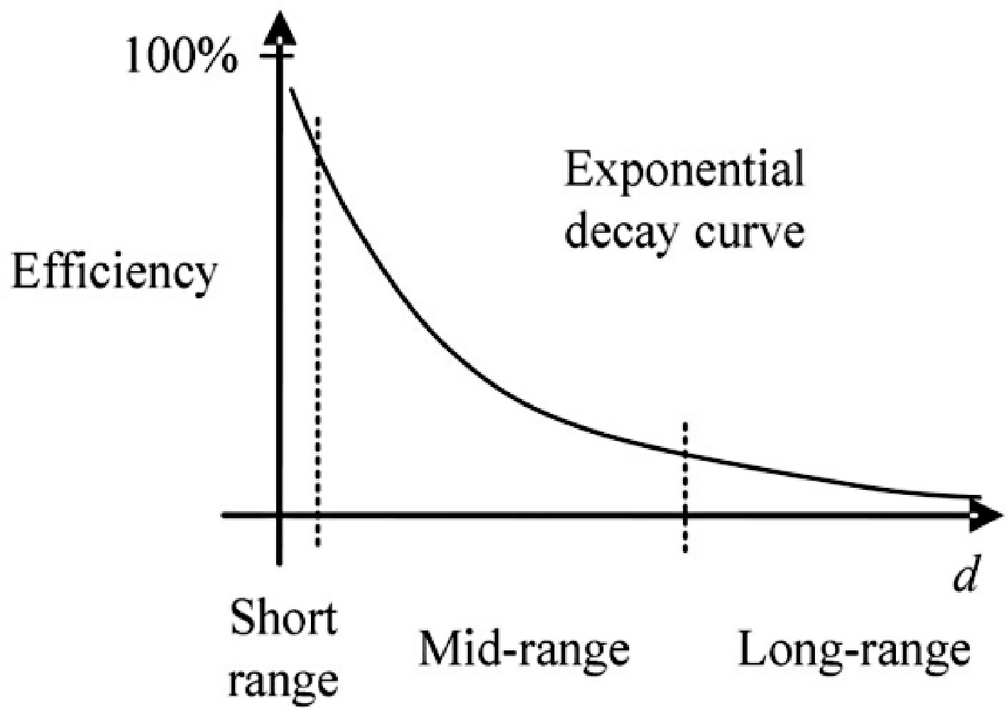
      Figure 1. 

      Exponential decay curve of the efficiency as a function of transmission distance d for a two-stage IPT system[4].

      To increase the power transfer distance, relay coils are employed in the IPT system. Relay coil-based IPT systems can be classified into three types: the four-coil IPT system[57], the three-coil IPT system[814], and the domino IPT system[1517]. Among these types, in the domino IPT system, relay coils are typically placed in a fixed location, primarily applied to insulation. In contrast, the locations of relay coils for the three and four-coil IPT systems are relatively flexible. Relay coils have practical applications in WPT by enhancing transmission efficiency and range. They are used to extend charging distances in electric vehicle (EV) charging, enable simultaneous power supply to multiple devices in smart homes, improve charging efficiency for biomedical implants, and facilitating remote power delivery in harsh environments such as high-temperature industrial settings or underwater. Thus, relay coils are widely applicable in fields such as transportation, smart devices, industrial automation, and healthcare.

      In 2007, an MIT team successfully transferred 60 W of power to the load over a 2 m transmission distance using a four-coil IPT system[5]. Subsequent studies revealed the pivotal role of the two additional coils in the four-coil WPT systems for impedance matching[6,7]. In the study by Chen et al.[6], a tuning method is implemented to transfer the required power with maximum efficiency. In the study by Cheon et al.[7], detailed explanations for the impedance matching of the four-coil IPT system to maximize power transfer are presented.

      It is indicated in the research by Kiani et al.[8] that the three-coil WPT can achieve higher output power than the four-coil WPT system. And the three-coil WPT system is being implemented in implant devices[911]. Comparisons of the system efficiency between the two-coil and three-coil WPT systems are discussed in previous research[1214].

      Most existing research on relay coil systems has been conducted on conventional planar-type IPT systems, with insufficient investigations into spatial IPT systems. Relay coils show great potential for spatial IPT systems due to their beneficial power transfer characteristics. Spatial IPT systems exhibit excellent misalignment tolerance and allow for flexible placement of the receiver. The application of spatial IPT systems in containers has been widely studied[1821]. In previous studies[18,19], the cavity transmitter adopts the form of an octagonal prism structure and cubic structure. These spatial IPT systems provide power to receivers located all around the container at a fixed angle. In the study by Mao et al.[20], a double-layer coil structure based on the octagonal prism structure has been proposed to uniform the magnetic field (B-field) distribution. In the study by Wang et al.[21], a folded coil design for the spatial IPT system based on the cubic and octagonal prism structure has been proposed.

      However, wireless charging containers face the challenge of low power transfer capability due to the flexible locations of the receiver. Therefore, investigations into the use of relay coils in wireless charging containers are necessary. The wireless power transfer system with a wireless power modulator (WPM), as mentioned, has been widely applied to implant devices[10,11], and portable equipment. Additionally, cubic wireless charging containers have been used in small-scale applications, such as biomedical implants[11], and large-scale applications, such as wireless charging rooms[19]. One of the primary issues with wireless charging containers is that the received power is relatively low due to weak coupling and the small size of the receiver coil. Therefore, this paper proposes using a WPM in wireless charging containers to regulate power and improve the WPT system.

      In this paper, a relay coil is implemented in a cubic wireless charging container which has a diameter of 1 m. The relay coil acts as a WPM capable of boosting or decreasing the output power. Two critical effects of the WPM, namely the resonant frequency of the WPM and the distance between the WPM and the transmitter and receiver, are analyzed. Different sets of experiments are conducted, and some interesting findings from the experiments are summarized.

    • In this section, the WPT system of the wireless power container configured with a WPM is theoretically analyzed. Firstly, the magnetic field inside the container is simulated and compared using Ansys Maxwell for the following scenarios: (1) Coil I working individually; (2) Coil II working individually; and (3) Both sets of coils working simultaneously. Then, the circuit of this WPT system is simplified and analyzed.

    • Following the folded coil design for the cubic wireless charging container proposed in previous research[21], the two coils (Coil I and Coil II) in the container are orthogonal in space and connected in series, as illustrated in Fig. 2. According to the study by Wang et al.[21], utilizing a 33% folding coil configuration within a cubic container results in a more uniform internal magnetic field with reduced deviation, making it a more suitable design for experimental purposes compared to other percentage configurations, so the folding ratio of each coil is set at 33%.
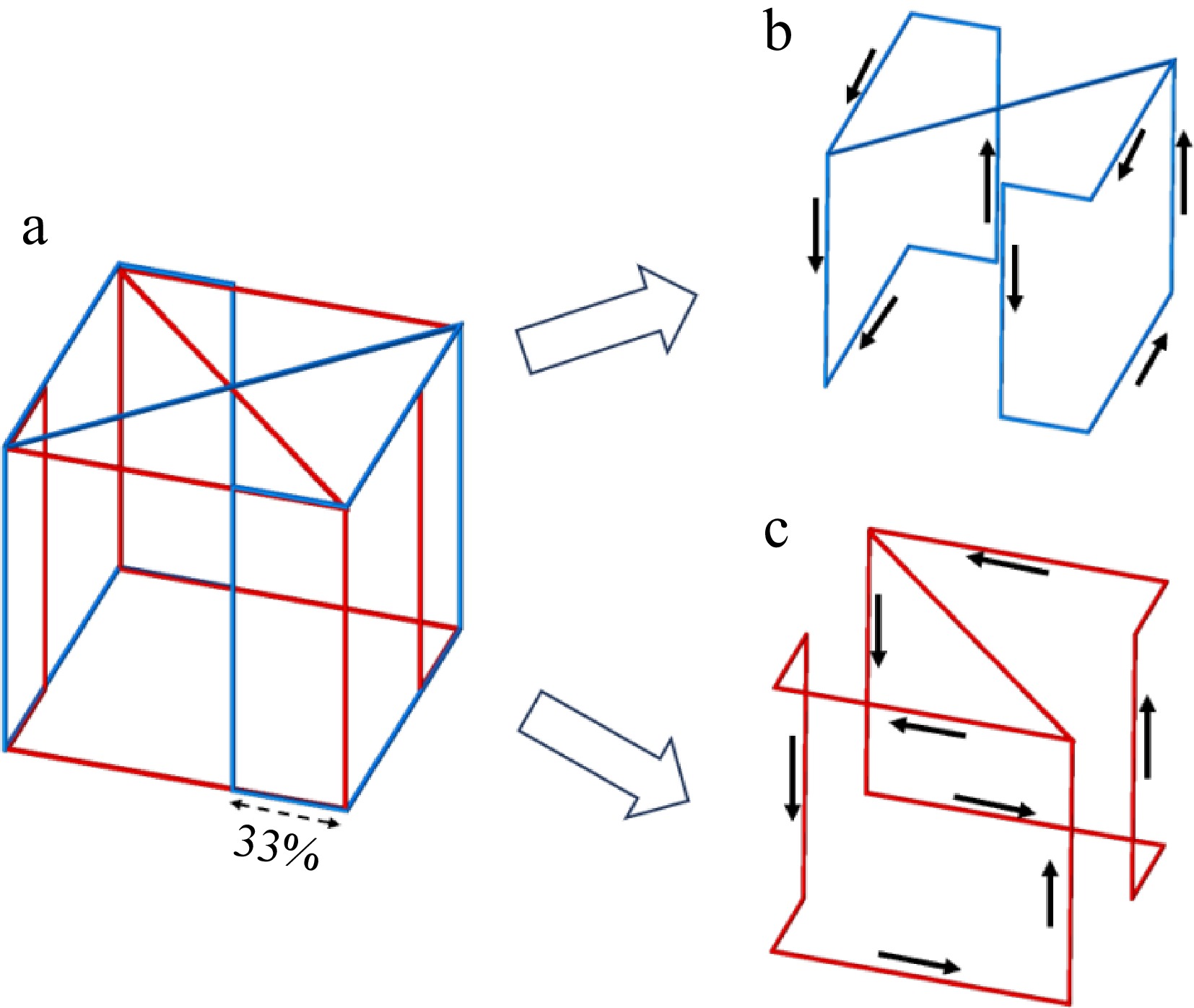
      Figure 2. 

      Coil winding and current flow profile of the container. (a) WPT system for wireless charging incubator configured with a WPM, (b) Coil I in transmitter, (c) Coil II in transmitter.

      The two orthogonal folding coils are capable of generating relatively uniform magnetic fields within the wireless charging container. Operation of a singular coil allows the receiver to harness significant energy in a specific direction (2π of solid angles), a phenomenon that will be substantiated through ensuing experimental validation. The concurrent operation of both coils, when connected in series, facilitates the synthesis of a magnetic field, thereby enabling the receiver to absorb significant energy from all directions (4π of solid angles). The distribution of the magnetic field inside the container, during the operation of one of the coils in the transmitter (Coil I & Coil II), is shown in Fig. 3.
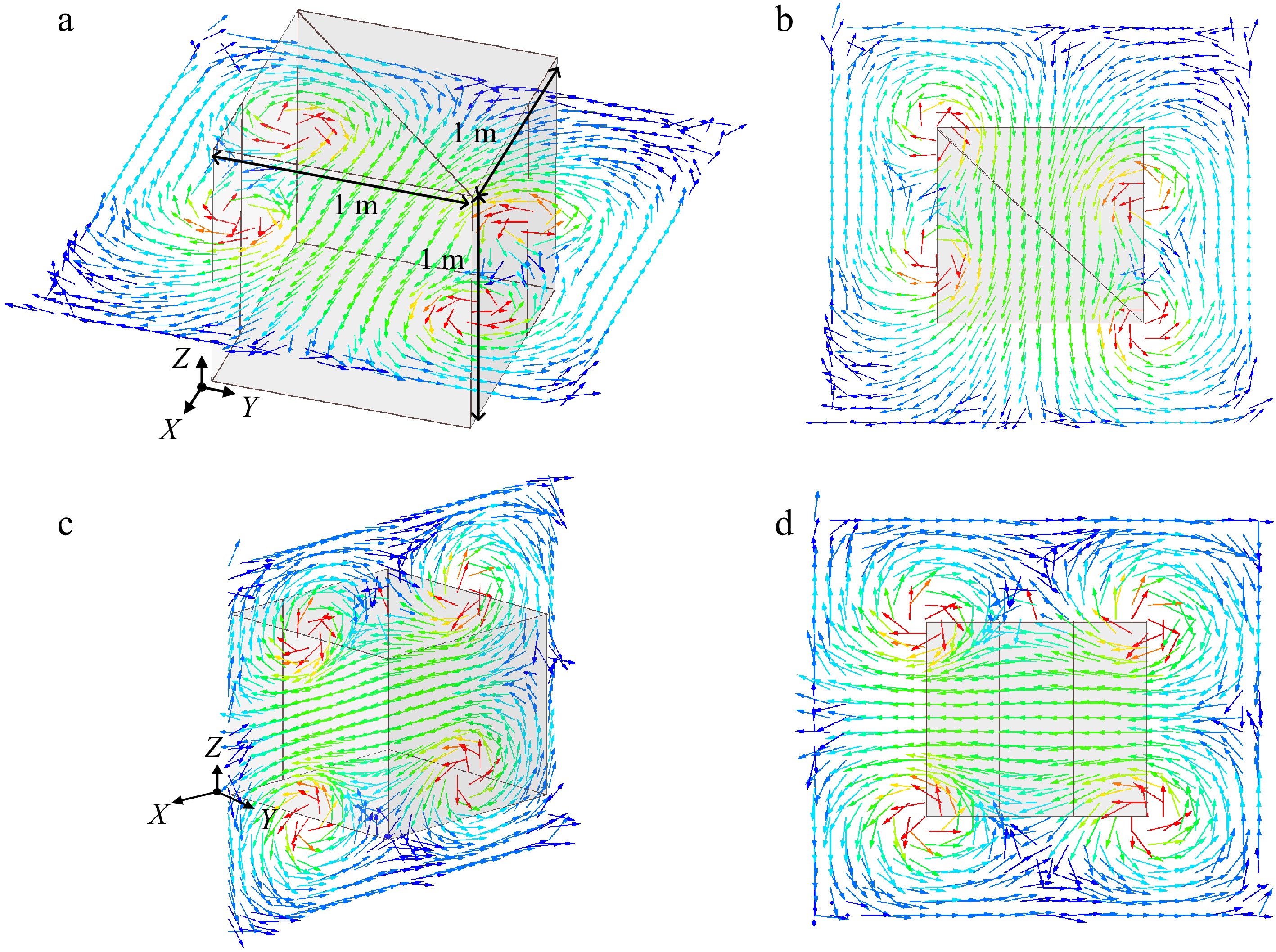
      Figure 3. 

      Magnetic flux distribution inside the wireless charging container for one coil (Coil II for example) operation. (a) Horizontal plane, (b) top view of magnetic flux distribution, (c) vertical plane, (d) side view of magnetic flux distribution.

      The transmitting coil utilized in this experiment consists of two orthogonal sets of coils. When an alternating current of identical frequency and phase is passed through these coils, it generates two orthogonal magnetic fields. These fields combine to form a single spatial magnetic field. As shown in Fig. 4, due to their perpendicular orientation, the magnetic fields do not interfere with each other but result in a 90° phase difference in the receiving coils. This configuration allows the receiver to capture the same amount of energy regardless of its orientation in perpendicular planes. To reduce the number of variables and simplify the experimental procedure, this study focuses on a single transmitting coil. In practical applications, the overall effect would be the superimposition of the two coils.
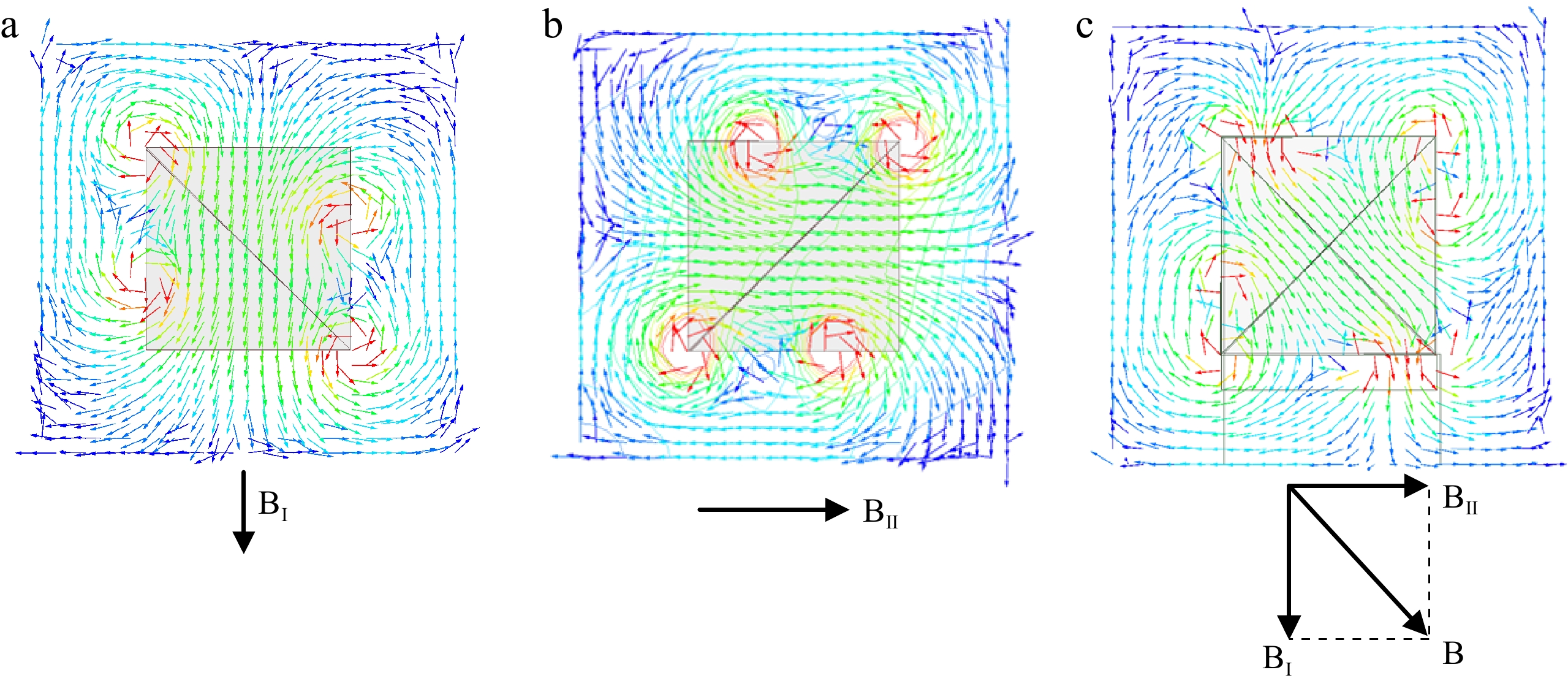
      Figure 4. 

      Top view of magnetic flux distribution when different coils operating and their relationship. (a) Coil I operating, (b) Coil II operating, (c) Coil I and Coil II operating.

    • The equivalent circuit model of the WPT system with WPM can be simplified as a three-coil WPT system as shown in Fig. 5a, and the simplified equivalent circuit model is shown in Fig. 5b. The transmitter, WPM and receiver are adopted series compensated topology and the inductance for the transmitter, WPM, and receiver are denoted as L1, LM, and L2, respectively. C1, CM, and C2 are the compensated capacitors. M1M, M2M, and M12 represent the mutual inductance between L1 and LM, LM and L2, L1 and L2, respectively.
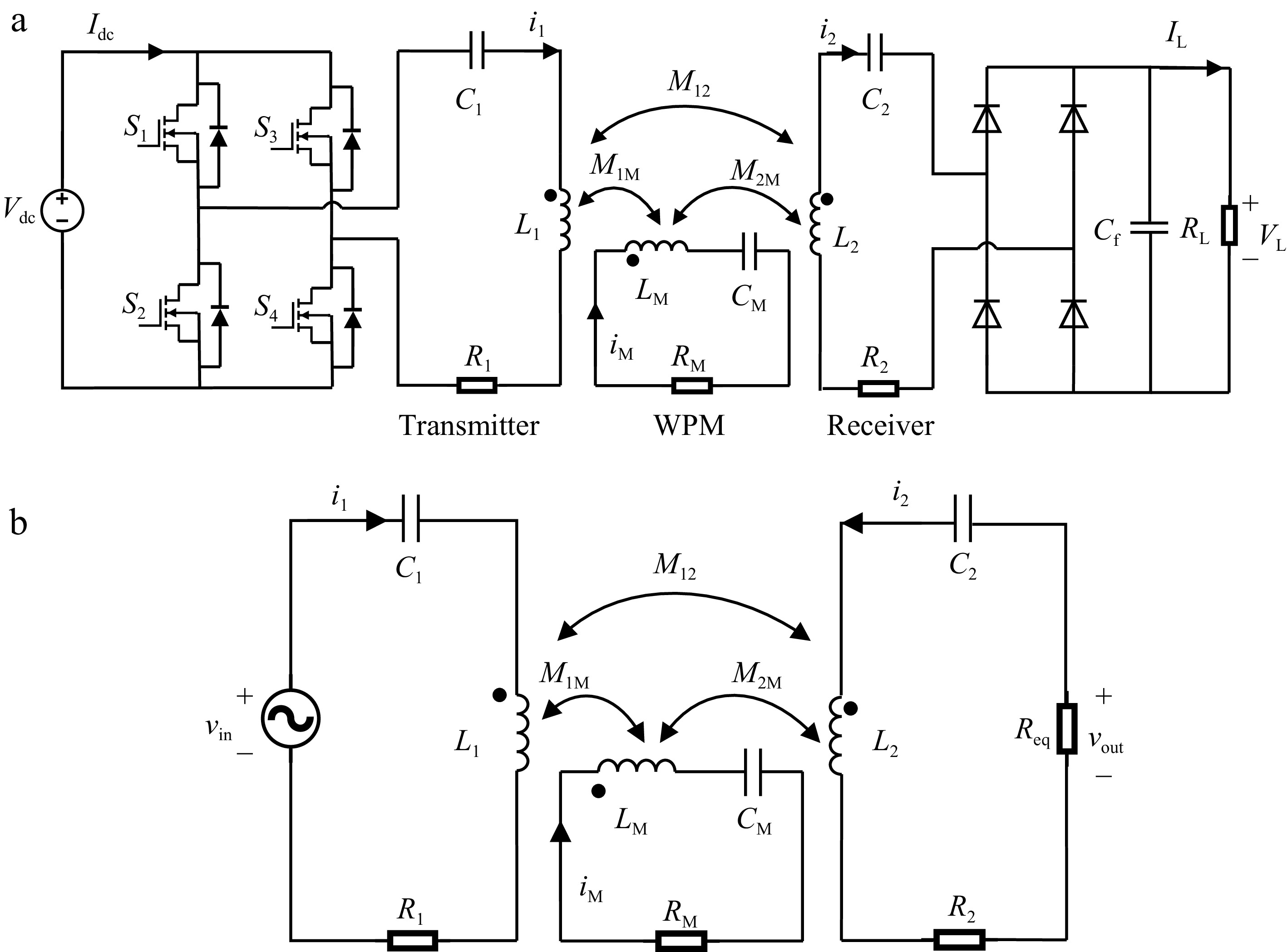
      Figure 5. 

      (a) Equivalent circuit model for the proposed WPT system, and (b) the simplified circuit model.

      This simplified model and the following equations already consider the possible ohmic losses caused by the power supply, the inverter and the rectifier. It also considers the cross-coupling between the receiver and transmitter coils. From the simplified circuit model in Fig. 5b, The impedance of the transmitter loop, the WPM loop and the receiver loop can be expressed respectively as:

      Z1=R1+jω0L1jω0C1 (1)
      ZM=RM+jω0LMjω0CM (2)
      Z2=R2+Req+jω0L2jω0C2 (3)

      where, Z1, ZM, and Z2 are the impedance of the transmitter loop, the WPM loop and the receiver loop respectively. According to Kirchhoff voltage law (KVL), the three loops in system can be expressed as:

      Vin=Z1I1+jω0M1MIM+jω0M12I2 (4)
      0=jω0M1MI1+ZMIM+jω0M2MI2 (5)
      0=jω0M12I1+jω0M2MIM+Z2I2 (6)

      where, Vin is the voltage vector of the equivalent simplified AC input power supply vin, I1, IM, and I2 are the current vectors of the i1, iM, and i2.

      Then, the output current and power flow to the load P2 can be expressed as:

      I2=(k1Mk2M+jk12QM)[X02j(k1Mk2Mk12)]ω0L1L1L2Vin (7)
      P2=|I2|2Req (8)

      where, X0=k21MQ2+k212QM+k22MQ1+Q1QMQ2. k1M=M1ML1LM, k2M=M2ML2LM, k12=M12L1L2 are the coupling coefficients, and Q1=Z1ω0L1, QM=ZMω0LM, Q2=Z2ω0L2 are the quality factors.

      The output power is dependent on the impedance of the transmitter, receiver, and the WPM, as well as the mutual inductance between the coils as can be seen from Eqns (7) & (8). For a given system with fixed coil parameters, the impedance can be regulated by adjusting the operating frequency. Here, to simplify the analysis and based on a practical IPT system, the resonant frequencies of the transmitter and receiver are set to be the same as the operating frequency. The resonant frequencies of the relay coil are set at different values. The mutual inductance of the coils is regulated by adjusting the placement of the WPM. The performance of the power flow regulation of the WPM is demonstrated in the experiment.

    • Two different types of experiments for the WPT system with WPM were conducted. In the first type of experiment (Experiment A), the resonant frequencies for the transmitter, WPM, and receiver are set the same. In the second type of experiment (Experiment B), the resonant frequency for the WPM is intentionally set differently from the resonant frequency of the transmitter and receiver. It has been proposed by Yang et al.[22] that biasing the frequencies of the WPM differently from the transmitter and receiver can regulate the output power capability. Hence, different resonant frequencies of the WPM are designed in this paper to explore their performance in the cubic wireless charging container.

      The photograph of the coil structure used in the experiment is shown in Fig. 6. Coil II was activated in this experiment. The transmitter coil, receiver coil, and WPM coil are tuned with capacitor series compensation. The receiver was fixed at the center. The main parameters of the system are listed in Table 1.
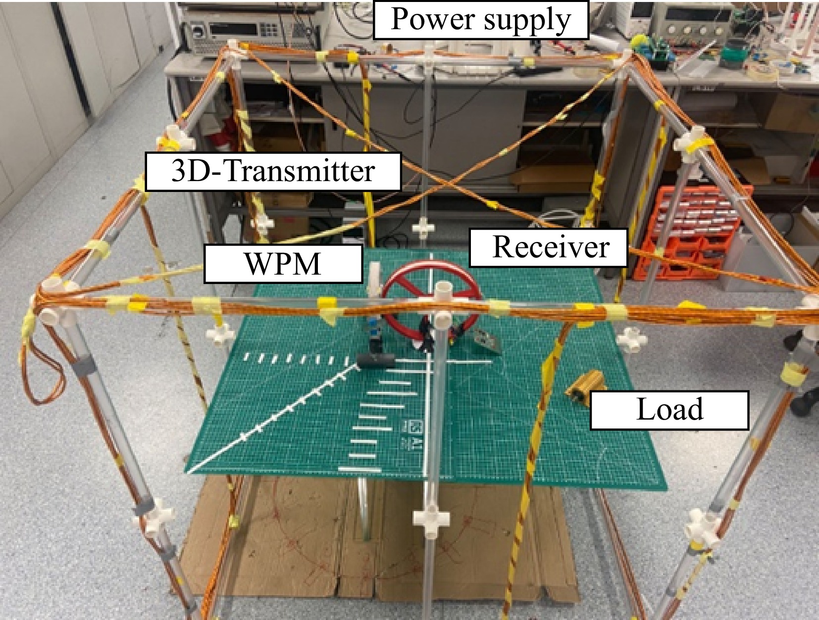
      Figure 6. 

      Photograph of the experimental setup.

      Table 1.  Parameters for the WPT system in the experiment.

      Parameters Value
      Operation frequency 100 kHz
      RMS value of the i1 3 A
      Size of the transmitter (length × width × high) 1 m × 1 m × 1 m
      Diameter of receiver 12.5 cm
      Turns of receiver 11
      Diameter of WPM 10.5 cm
      Turns of WPM 11
      Load 10 Ω
      Inductance of L1 156.6 μH
      Inductance of LM 47.4 μH
      Inductance of L2 64.5 μH
      ESR of L1 0.2 Ω
      ESR of LM 0.2 Ω
      ESR of L2 0.7 Ω

      The operating frequency of 100 kHz is commonly used in both academic and industry applications. This frequency typically does not interfere with other wireless communication devices (e.g., Wi-Fi, Bluetooth), which minimizes the impact on surrounding electronic equipment and offers an advantage in terms of electromagnetic compatibility. Additionally, on the one hand, the components, such as inverters and controllers for the 100 kHz systems are relatively inexpensive and readily available, making them suitable for the experiment. On the other hand, this frequency is followed by the Qi standard, which is widely used in real applications.

      In the experiment, distance represents the length of the line connecting the center of the receiver and the center of the WPM. The diameter D of the receiver coil is used as the reference value for distance (per unit value*). The placement scheme of a WPM is designed in two sets, namely Set 1 and Set 2, as shown in Fig. 7. The main difference between the two sets is that the placement of the WPM of one set is orthogonal compared to the other set.
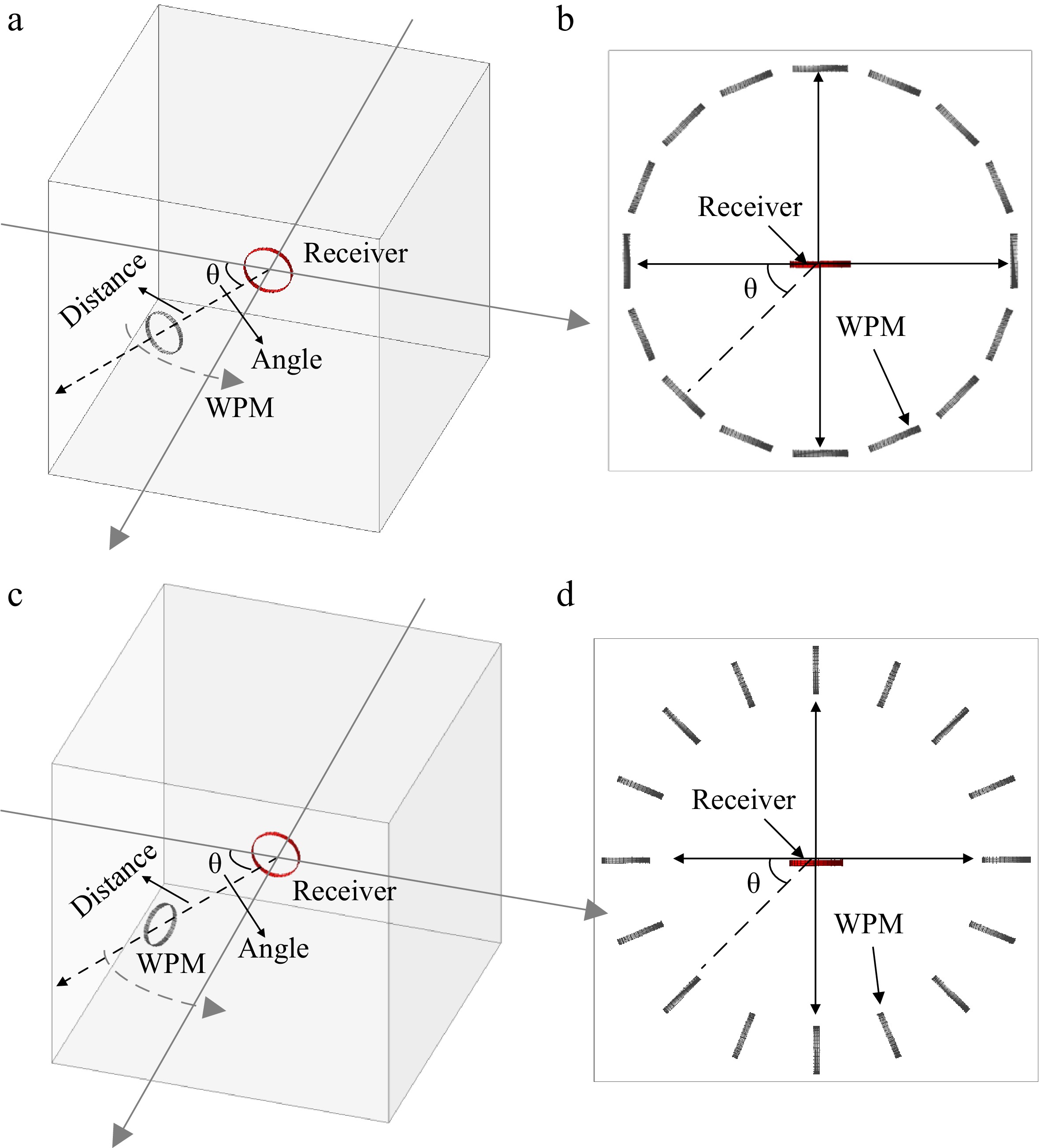
      Figure 7. 

      Two different placement scheme designs for a WPM. (a) Set 1 (left) and its top view (right), (b) Set 2 (left) and its top view (right).

      Since the magnetic flux inside the wireless charging container (as shown in Figs 3 & 4) is relatively weak at the center compared to the interior edges of the container, the receiver is fixed at that center to explore the effect of the WPM on the output power by different placement to improve the WPT system. The position of the WPM can be flexibly adjusted based on the practical location of the receiver. Additionally, the movement of the WPM provides a flexible way to regulate the output power.

      The different placement angles of the WPM based on the angle between the receiver coil and the WPM are categorized into four cases. Due to the spatial symmetry of the magnetic field shown in Figs 3 & 4, four cases (i.e., Case A, Case B, Case C, and Case D) are executed in experiments A and B. The relative position between the WPM and receiver in these cases are illustrated in Fig. 8.

    • In Experiment A, the resonant frequency for the transmitter, receiver, and WPM is set to the same as the operating frequency of 100 kHz. This section focuses on the effect of the placement of the WPM relative to the receiver in the container on output power. The power received by the receiver (power output to the load) when the WPM is not added to the wireless charging container is initially tested, and it is denoted as Pref = 2.35 W, which serves as a reference value in later experiments. As previously mentioned, the distance is represented by the nominal value (per unit*) of the diameter of the receiver coil (12.5 cm) as a base. The relationship between the power transferred to the load and the distance (*) is shown in Fig. 9 for each of the four different cases in Set 1 and Set 2.
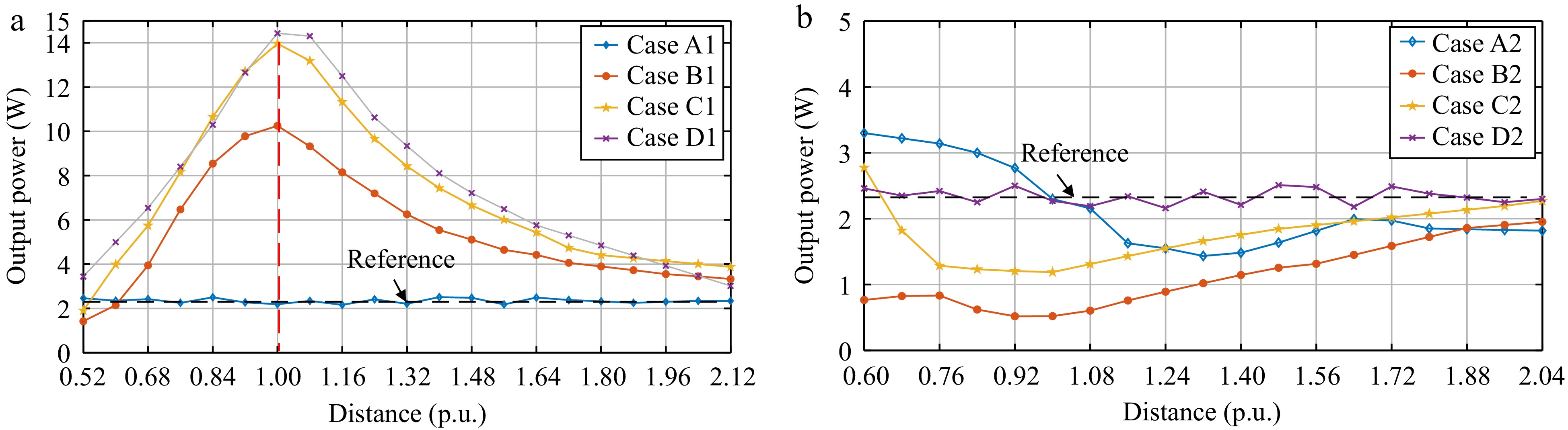
      Figure 9. 

      Variations of the output power to the distance for (a) cases of Set 1, and (b) cases of Set 2.

      It can be observed from Fig. 9a that the placement design of WPM in Set 1 enhances the output power in most cases, surpassing the reference value. The findings for Fig. 9a can be summarized as follows:

      (1) The results of the experiment show that when the two coils (receiver and WPM) are very close to each other and facing the same orientation, the output power is lower than the reference value (weakening effect).

      (2) With the rotation angle increasing in Set 1, the output power increases. The maximum output is achieved in Case D (i.e., the WPM is coaxial with the receiver) with d* = 1.

      It is worth emphasizing in particular that the optimal output power occurs when the two coils are at a distance of the receiver diameter (distance 1* in the figure) and the same orientation, not when they are close to each other and have the same orientation. As shown in Fig. 9b, the performance of Set 2 is opposite to Set 1, and the findings of Fig. 9b can be summarized as follows:
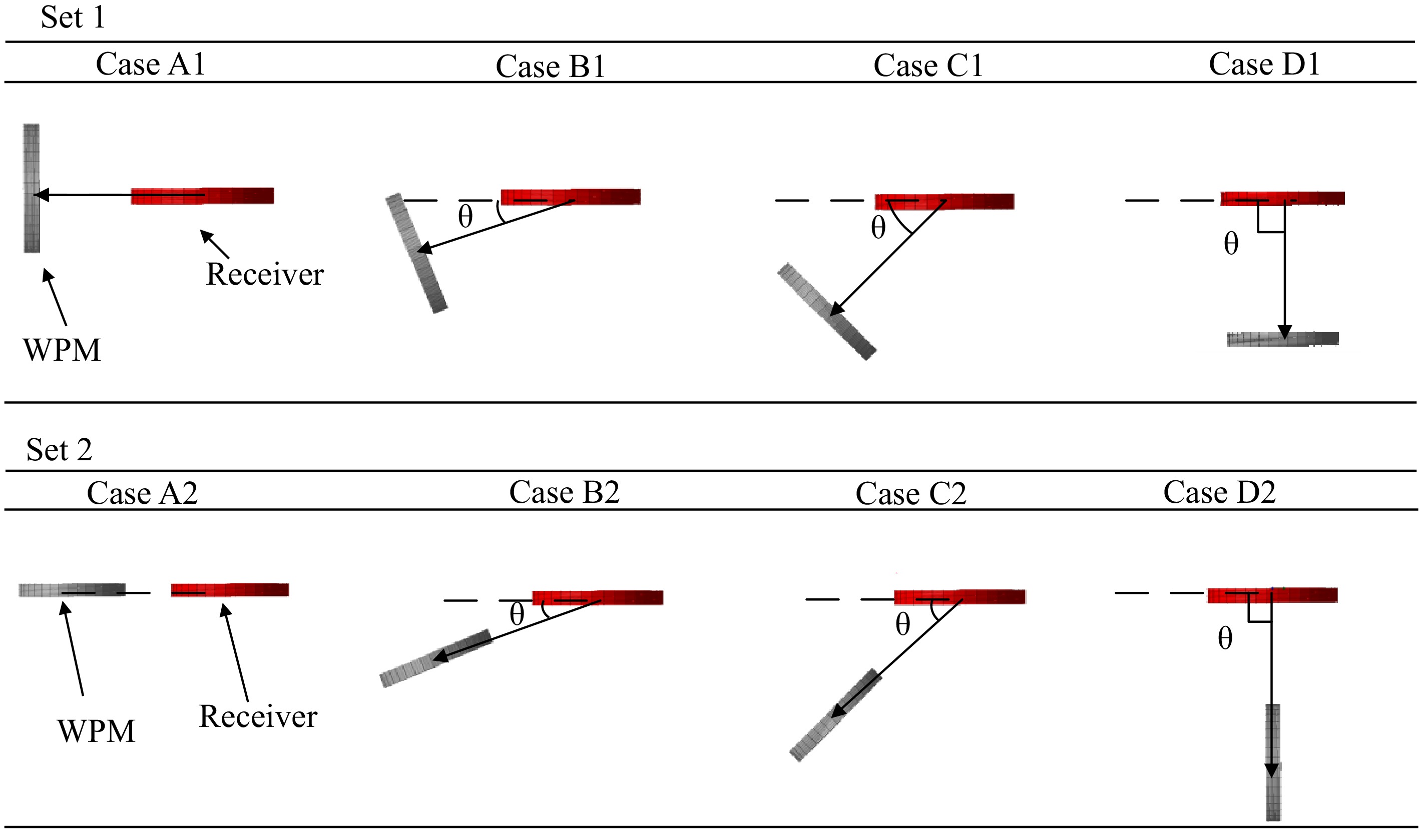
      Figure 8. 

      Placement cases of WPM in Set 1 and Set 2.

      (1) In Set 2, the output power decreases as the angle and distance between the WPM and receiver vary. The most significant power drop occurs when the distance is equal to the receiver coil's diameter (d* = 1), as seen in cases B2 and C2.

      (2) As the rotation angle increases in Set 2, the reduction in output power diminishes. Additionally, the placement of the WPM does not significantly affect the output power, as demonstrated in Case D of Set 2.

    • In Experiment B, the self-resonant frequency (SRF) of the WPM is set differently from the operating frequency. The value of the SRF for the WPM is shown in Table 2.

      Table 2.  Setting of the self-resonance point of the WPM.

      No. SRF of WPM (kHz) Deviation (kHz)
      1 102.0 +2 kHz
      2 101.2 +1.2
      3 100.5 +0.5
      4 100.0 0 (operation frequency)
      5 99.5 −0.5
      6 98.6 −1.4
      7 97.9 −2.1

      The output power can be regarded as a function of the distance (per unit) and SRF of the WPM. The relationship between the output power and the distance (per unit) under different SRFs is shown in Fig. 10.
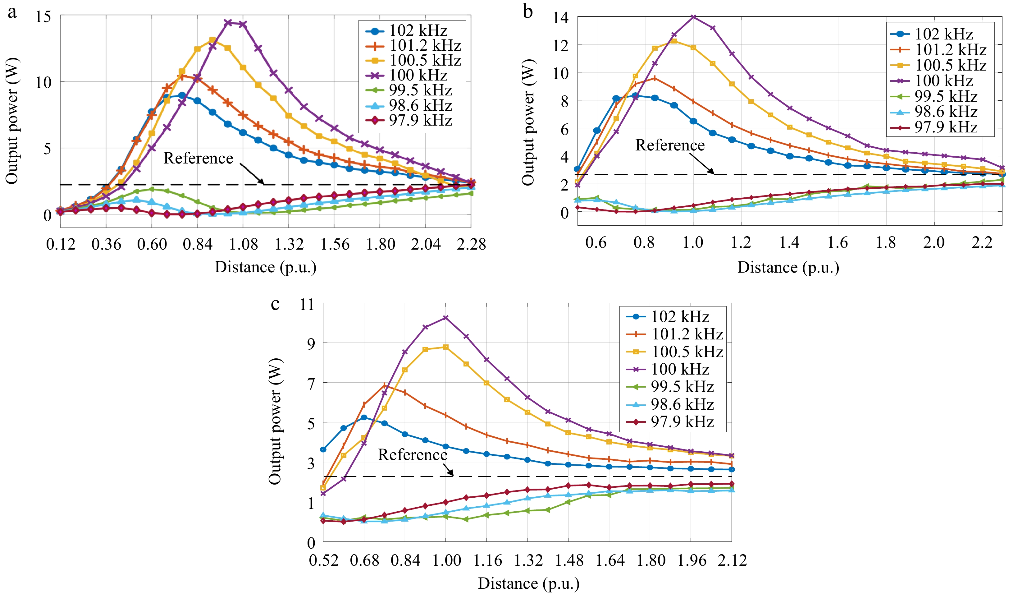
      Figure 10. 

      Variations of output power with the distance (*) under the different SRFs for (a) Case D1, (b) Case C1, and (c) Case B1.

      It can be seen from Fig. 10 that in Set 1, the WPM has a boosting effect on the output power when the SRF of the WPM is set in a nearby frequency range above the system's operating frequency (> 100 kHz). This power boost effect results in an optimal value at a certain distance, which is consistent with the conclusions of the previous section. It is also noted that this optimal power deviates from the nominal distance 1* (no longer the diameter of the receiver) because of the deviation in the SRF of the WPM.

      Conversely, when the SRF of the WPM is set in a nearby frequency range below the system operating frequency (< 100 kHz), the WPM has a weakening effect on the output power. The optimal power weakening effect also does not occur at the distance 1*, which deviates with the SRF of the WPM.

      The output power as a function of the distance (*) between the WPM and the receiver in different cases in Set 2 are shown in Fig. 11.
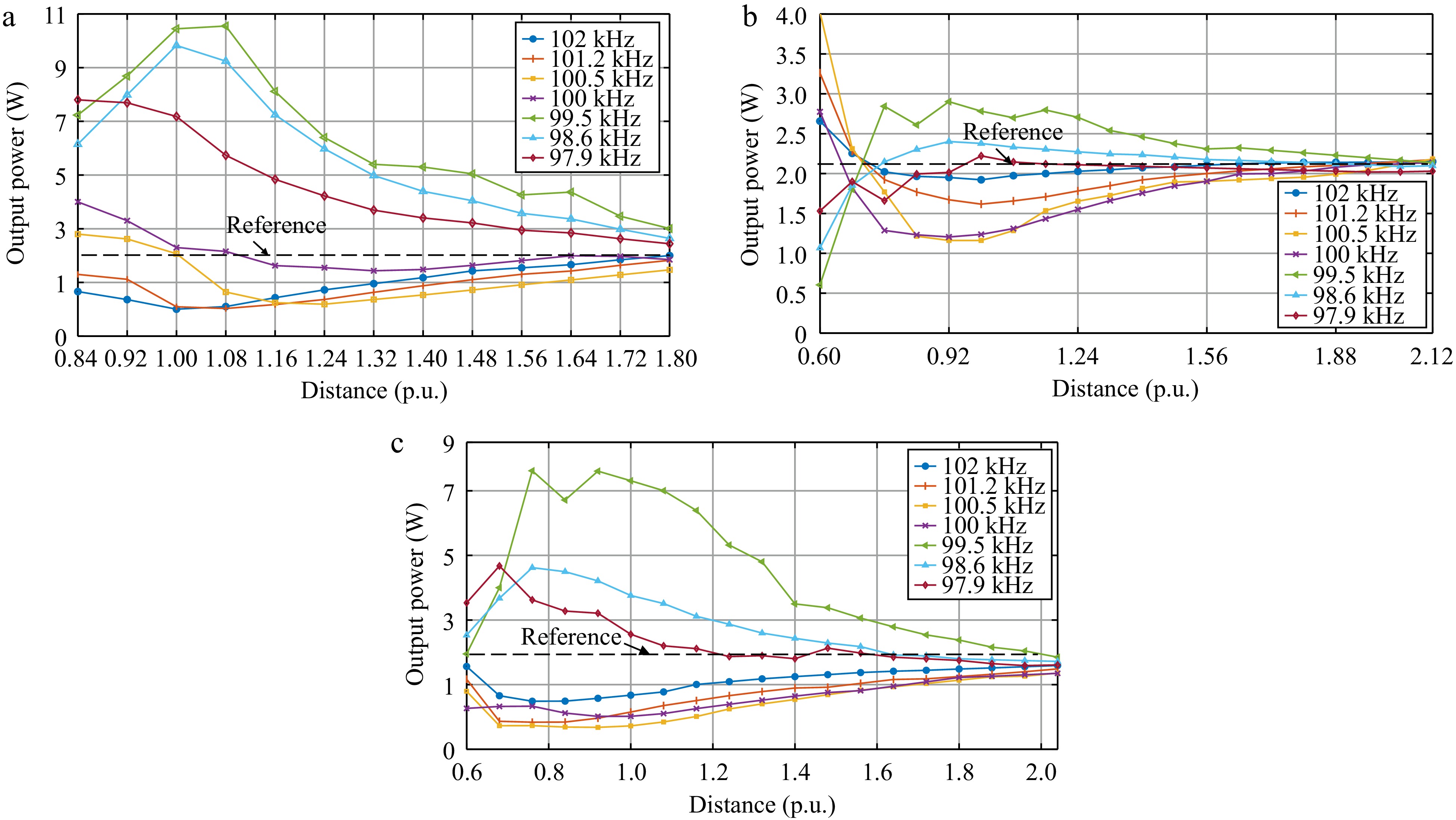
      Figure 11. 

      Variations of output power with the distance (*) under the different SRFs for (a) Case A2, (b) Case B2, and (c) Case C2.

      The results in Fig. 11 demonstrate that the designs in Set 2 and Set 1 has distinctly different effects on the output power. In Set 2, when the self-resonance point of the WPM is set at a frequency above the system operating frequency (> 100 kHz), the WPM functions as a power-boosting regulator. The optimal power boost effect shifts with changes in the WPM's self-resonance frequency.

      Conversely, in Set 1, when the self-resonance point of the WPM is set below the system operating frequency (< 100 kHz), the WPM acts as a power-weakening regulator. The location of the optimal power-weakening effect shifts with deviations in the WPM's self-resonance frequency. The overall trend of the SRF of the WPM for the designs of Set 1 and Set 2 with respect to the output power is summarized in Fig. 12.
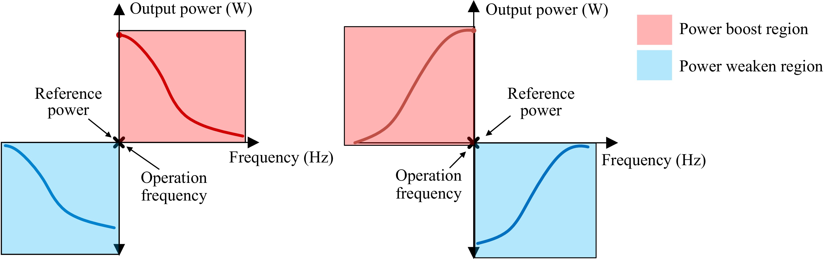
      Figure 12. 

      Effects of the self-resonance points deviation of the WPM and output power (a) Set 1, and (b) Set 2.

      Based on the experimental results and analysis, the output power of the receiver can be modulated using the WPM in this wireless charging container. When the frequency of the WPM is set slightly higher than the operating frequency and aligned with the placement orientation of Set 1, a power enhancement effect can be obtained. Conversely, when the frequency of the WPM is set slightly lower than the operating frequency and is placed at a distance equal to the receiver diameter as indicated by the placement orientation of Set 2, a power weakening effect can be achieved.

    • This paper presents a power modulation design for a cubic wireless charging container configured with a WPM. The management of the power flow can be realized in two ways, i.e., regulating the position and SRF of the WPM. Based on the two designs, two sets of WPM placement schemes are proposed. The results show that the WPM can have both enhancing and weakening effects on the output power of the receiver, which is a guiding significance for the application of WPM in practical power flow regulation.

      • The authors are thankful for the financial support from the Ministry of Education (MoE) Academic Research Fund (AcRF) Tier-1 RG134/23 and the A*Star MTC Young Individual Research Grant (YIRG) M23M7c0115.

      • The authors confirm contribution to the paper as follows: conceptualization: Yang Y, Yang J; data curation, formal analysis, methodology, visualization: Shang S, Tang K; funding acquisition: Yang Y; investigation: Shang S, Wang K, Tang K; project administration: Yang Y, Wang K, Liang R; resources: Yang Y, Liang R, Yang J; software, validation: Shang S, Wang K, Liang R, Tang K; writing - original draft: Shang S; supervision, writing - review & editing: Wang K, Yang Y. All authors reviewed the results and approved the final version of the manuscript.

      • The data that support the findings of this study are available from the corresponding author upon reasonable request.

      • The authors declare that they have no conflict of interest. Yun Yang is the Editorial Board member of Wireless Power Transfer who was blinded from reviewing or making decisions on the manuscript. The article was subject to the journal's standard procedures, with peer-review handled independently of this Editorial Board member and the research groups.

      • Copyright: © 2024 by the author(s). Published by Maximum Academic Press, Fayetteville, GA. This article is an open access article distributed under Creative Commons Attribution License (CC BY 4.0), visit https://creativecommons.org/licenses/by/4.0/.
    Figure (12)  Table (2) References (22)
  • About this article
    Cite this article
    Shang S, Wang K, Liang R, Tang K, Yang J, et al. 2024. Investigations on the use of a wireless power modulator in a wireless charging container. Wireless Power Transfer 11: e010 doi: 10.48130/wpt-0024-0010
    Shang S, Wang K, Liang R, Tang K, Yang J, et al. 2024. Investigations on the use of a wireless power modulator in a wireless charging container. Wireless Power Transfer 11: e010 doi: 10.48130/wpt-0024-0010

Catalog

  • About this article

/

DownLoad:  Full-Size Img  PowerPoint
Return
Return