


-
The expansion of the global economy has led to increased reliance on non-renewable energy sources, particularly oil and coal[1,2]. Consequently, this has resulted in the emission of significant quantities of pollutants, contributing to environmental degradation[3,4]. Electric vehicles (EVs) are considered a more environmentally friendly mode of transportation compared with traditional fuel-powered vehicles, widely recognized as a viable solution for reducing carbon emissions and mitigating global warming[5,6].
Existing EV charging systems are mainly wired. Wired charging can provide wider voltage gain and higher transmission efficiency, which is suitable for different models of EVs[7]. However, it requires wires to connect the EV to a power source, which is not convenient in certain scenarios, such as bad weather[8]. In contrast, wireless power transfer (WPT) technology utilizes electromagnetic induction to transmit energy without physical wires, which significantly improves the safety and convenience of charging[9,10]. But wireless charging is limited by relative position and coil type[11,12]. With the development of EVs, the demand for charging methods is increasingly diverse. The integration of the two charging methods is the future trend, which is more conducive to the promotion of EVs.
With the increasing popularity of EVs, one EV can serve as an energy supplier to charge another EV, especially in emergencies without charging stations around[13]. A wired charging method is proposed to directly connect the batteries of two EVs via on-board charger input ports and switches[14]. A novel vehicle-to-vehicle (V2V) charging technology was proposed, which is capable of grid-to-vehicle and V2V charging using a single-phase Cuk-derived DC-DC converter[15]. A new V2V interface was proposed, which was realized by directly connecting the motor winding neutral point of two EVs and the negative electrode rail of the drive system[16]. This approach facilitates the formation of an integrated bidirectional DC-DC converter to control the direction of the power flow. A strongly coupled V2V wireless charging system was proposed by Xie et al.[17]. Two power relay coils without compensating capacitors are introduced right beneath the transmitting (TX) and receiving (RX) coils and connected via twisted wires. This scheme requires two additional relay coils, which should align with the TX and RX coils. To solve the angular misalignment problem between the TX and RX coils, a novel magnetic coupler was proposed[18]. The simulation results show that the new structure can generate a stronger magnetic field than the traditional one. A prediction model of V2V charging is proposed, including driver model, motor model, battery model, EV model, and WPT model[19]. Through simulation, the results show that EVs using V2V charging can reach the destination earlier than EVs charging at traditional charging stations.
Both wired and wireless charging systems share similar power conversion stages, including coupled coils/transformers, resonant networks, inverters, and rectifiers[20,21]. Integrating similar components can achieve cost-effectiveness and enable operation in both wired and wireless charging modes. A hybrid wired/wireless charging system was proposed, which multiplexes the DC power module and switches the charging mode using two bidirectional switches[22]. A novel multifunctional converter for EV charging was proposed, which employs a set of power switches to output either a DC voltage for wired charging or a high-frequency AC voltage for wireless charging[23]. A DC-DC topology was proposed to include an additional receiver coil that multiplexes the rectifier on the EV side, enabling wireless charging[24]. However, there is currently no integrated wired and wireless charging solution for V2V charging[25,26].
This paper proposes a simple integrated solution of a reconfigurable wired and wireless V2V charging system, as depicted in Fig. 1. The coils are installed in the front of the EV. The series-series (S-S) resonant topology is adopted for the wireless charging mode, which requires coils to be aligned well to transmit power at maximum efficiency. It can be transformed into a bidirectional DC-DC converter for the wired charging mode, which allows misalignment of the coils and even long-distance placement. A simple circuit connection and switching pattern can achieve this target. Compared with previous V2V systems, the proposed V2V system is simpler, more cost-effective, and suitable for different charging conditions.
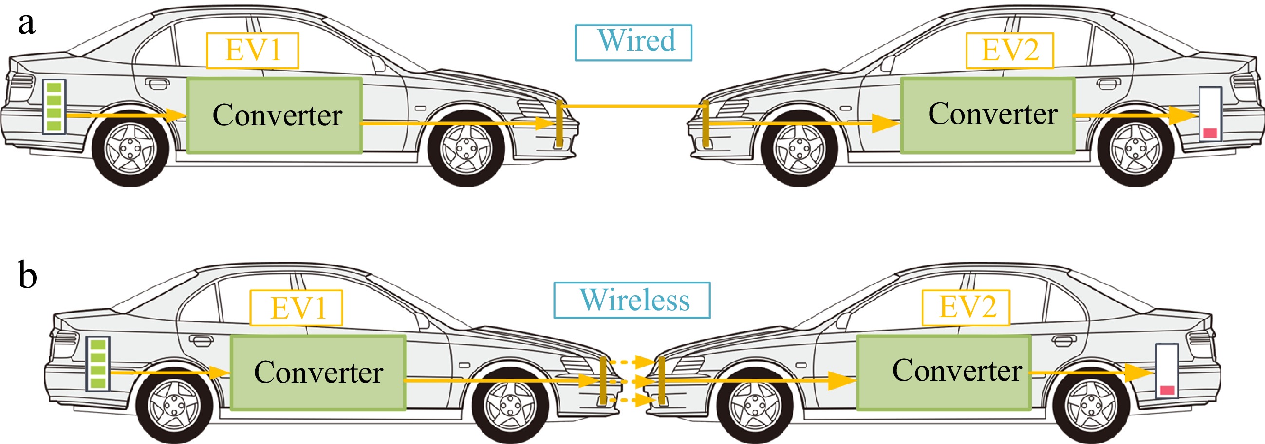
Figure 1.
Proposed V2V power transfer system. (a) Wired charging mode. (b) Wireless charging mode.
-
The topology of the proposed hybrid V2V charging system is shown in Fig. 2. V1 and V2 are the inverter and rectifier DC voltages, respectively. C1 and C2 are the compensation capacitors. L1 and L2 are the self-inductances. RL is the load resistance. M is the mutual inductance. A1, A2, B1, and B2 are the cables for the wired charging mode. S1-S8 are power MOSFETs.
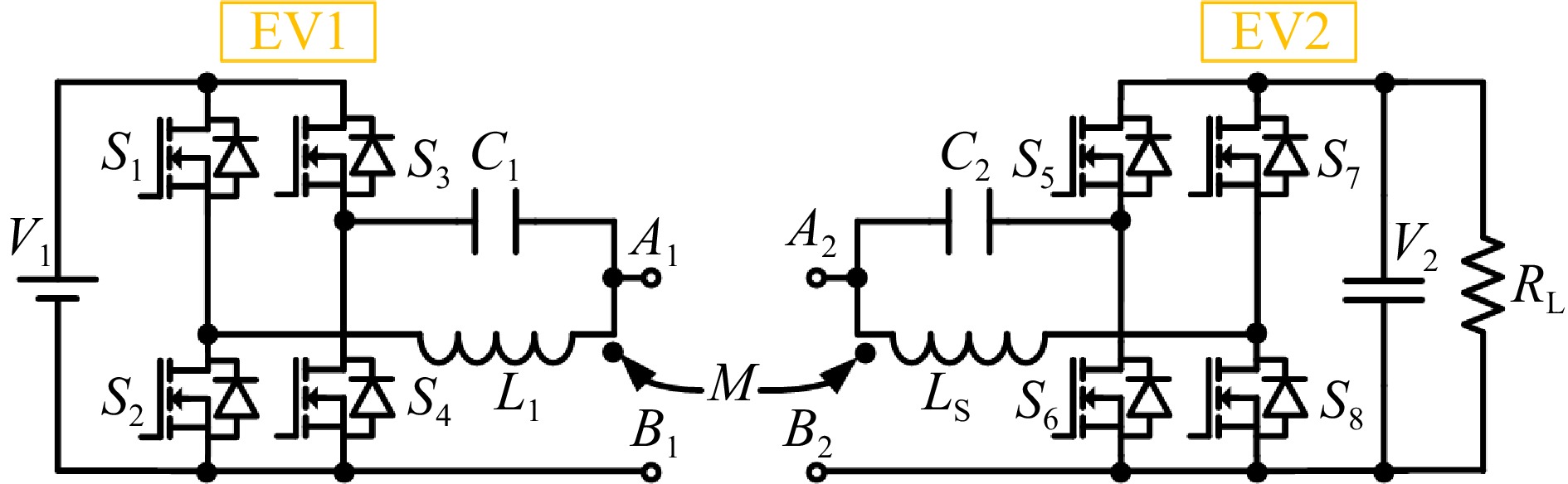
Figure 2.
Proposed integrated wired and wireless V2V charging system.
With different configurations, the proposed integrated V2V charging system can be switched to two operating modes, namely wired charging mode and wireless charging mode. In both modes, the system operates at frequency f.
Wired charging mode
-
The voltage range for EV batteries typically falls between 200 V and 450 V. If there is a need to transfer power across different voltage levels, wired charging becomes necessary. The proposed system is equivalent to a two-quadrant DC-DC converter when A1 is connected to A2 and B1 is connected to B2 and the switches are controlled by the driving rules shown in Fig. 3. The topology and equivalent circuit of wired charging mode are depicted in Fig. 4.
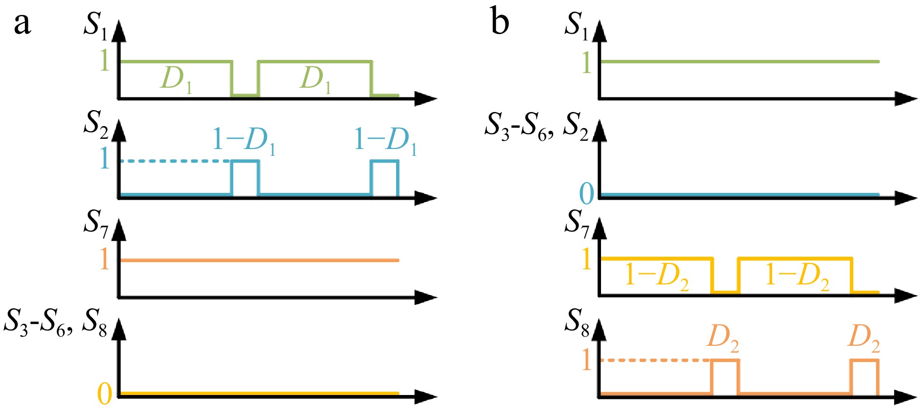
Figure 3.
Key waveforms of wired charging mode. (a) Buck converter. (b) Boost converter.
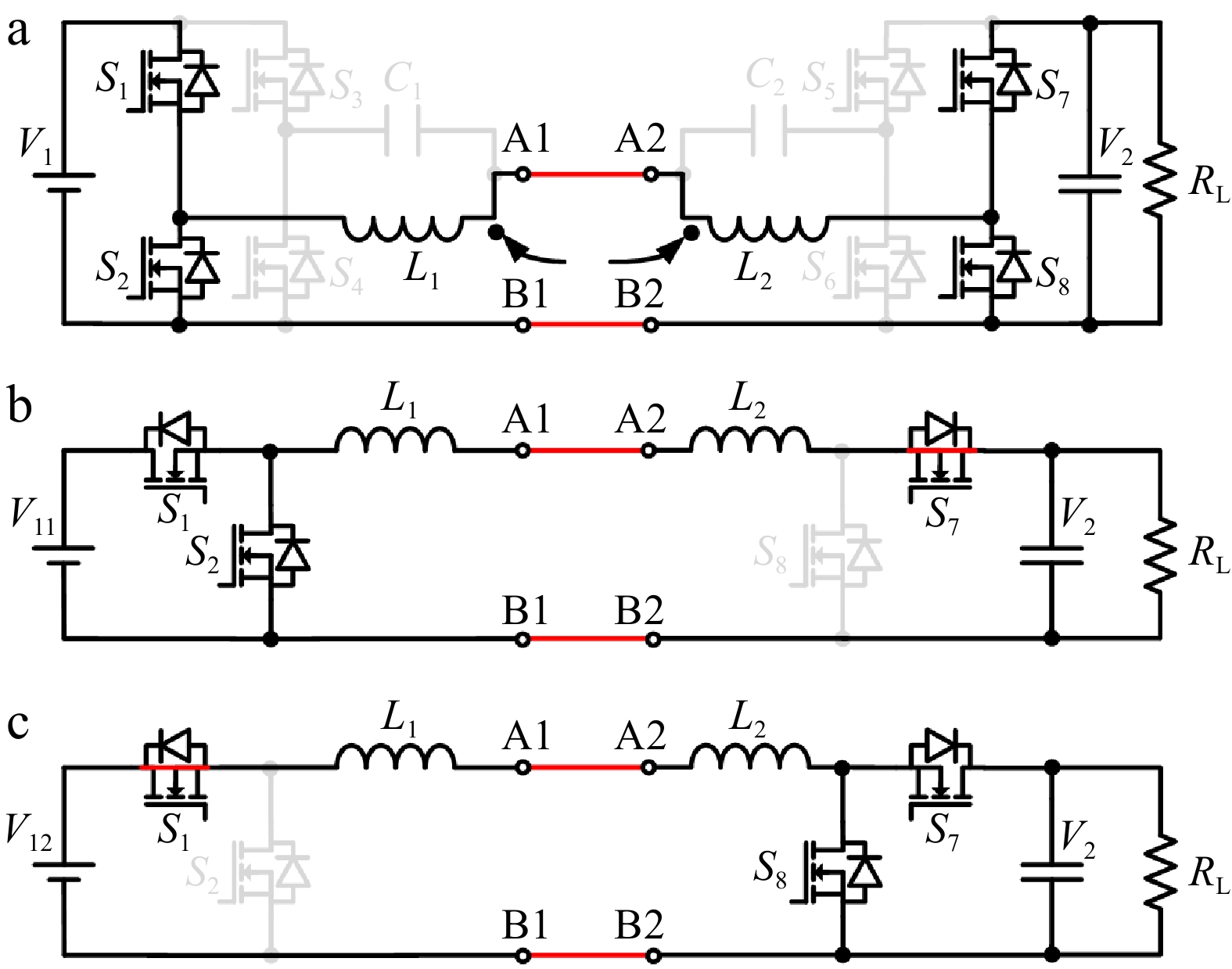
Figure 4.
V2V wired charging mode. (a) Topology. (b) Buck converter. (c) Boost converter.
Under the driving rule of Fig. 3a, the system can be further equivalent to a buck converter, as shown in Fig. 4b, where D1 is the duty cycle. V2 can be conducted as:
$ {V_2} = {D_1}{V_{11}} $ (1) Under the driving rule of Fig. 3b, the proposed system is equivalent to a boost converter, as shown in Fig. 4c, where D2 is the duty cycle. V2 can be conducted as:
$ {V_{\text{2}}} = \dfrac{{{V_{{\text{12}}}}}}{{1 - {D_2}}} $ (2) From Eqns (1) and (2), the output voltage is independent of the load, indicating that a constant-voltage (CV) output can be achieved in wired charging mode. In this mode, one EV can either buck or boost to charge another EV with a different voltage level. In addition, the circuit and control strategy of this mode is simple, with fewer power conversion stages, which can realize high-efficiency outputs.
Wireless charging mode
-
In bad weather or when the charging interface is damaged, it is suitable for wireless charging. The topology and equivalent circuit of wireless charging mode is depicted in Fig. 5, where U1 is the inverter AC output voltages. REQ is the equivalent AC load resistance. I1 and I2 are the corresponding currents. U1 and REQ can be expressed as:
$ {U_{\text{1}}} = \dfrac{8}{{{\pi ^2}}}{V_1} $ (3) $ {R_{{\text{EQ}}}} = \dfrac{8}{{{\pi ^2}}}{R_{\text{L}}} $ (4) Based on Kirchhoff's Voltage Law, I1 and I2 can be conducted as:
$ {I_{\text{1}}} = \dfrac{{{U_1}{R_{{\text{EQ}}}}}}{{{{\left( {2{\text{π }}fM} \right)}^2}}} $ (5) $ {I_{\text{2}}} = \dfrac{{{U_1}}}{{2{\text{π }}fM}} $ (6) In this case, a typical S-S topology is formed. The output current is independent of the load, indicating that a constant-current (CC) output can be achieved in the wireless charging mode.
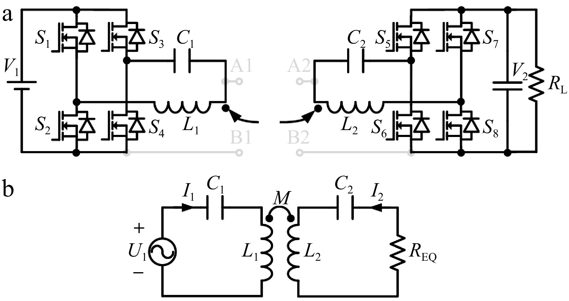
Figure 5.
V2V wireless charging mode. (a) Topology. (b) Equivalent circuit.
-
To validate the effectiveness of the proposed system, two hybrid V2V experimental prototypes are implemented, as depicted in Fig. 6. Note that in the wired charging mode, the mutual inductance is close to 0 due to the large distance between the TX and RX coils. The sizes of the coils are 300 mm × 300 mm. The specific parameters are provided in Table 1. Define the fluctuation coefficients of the output voltage, output current, and efficiency as:
$ \beta = \dfrac{{Max - Min}}{{Max + Min}} \times 100{\text{%}} $ (7) 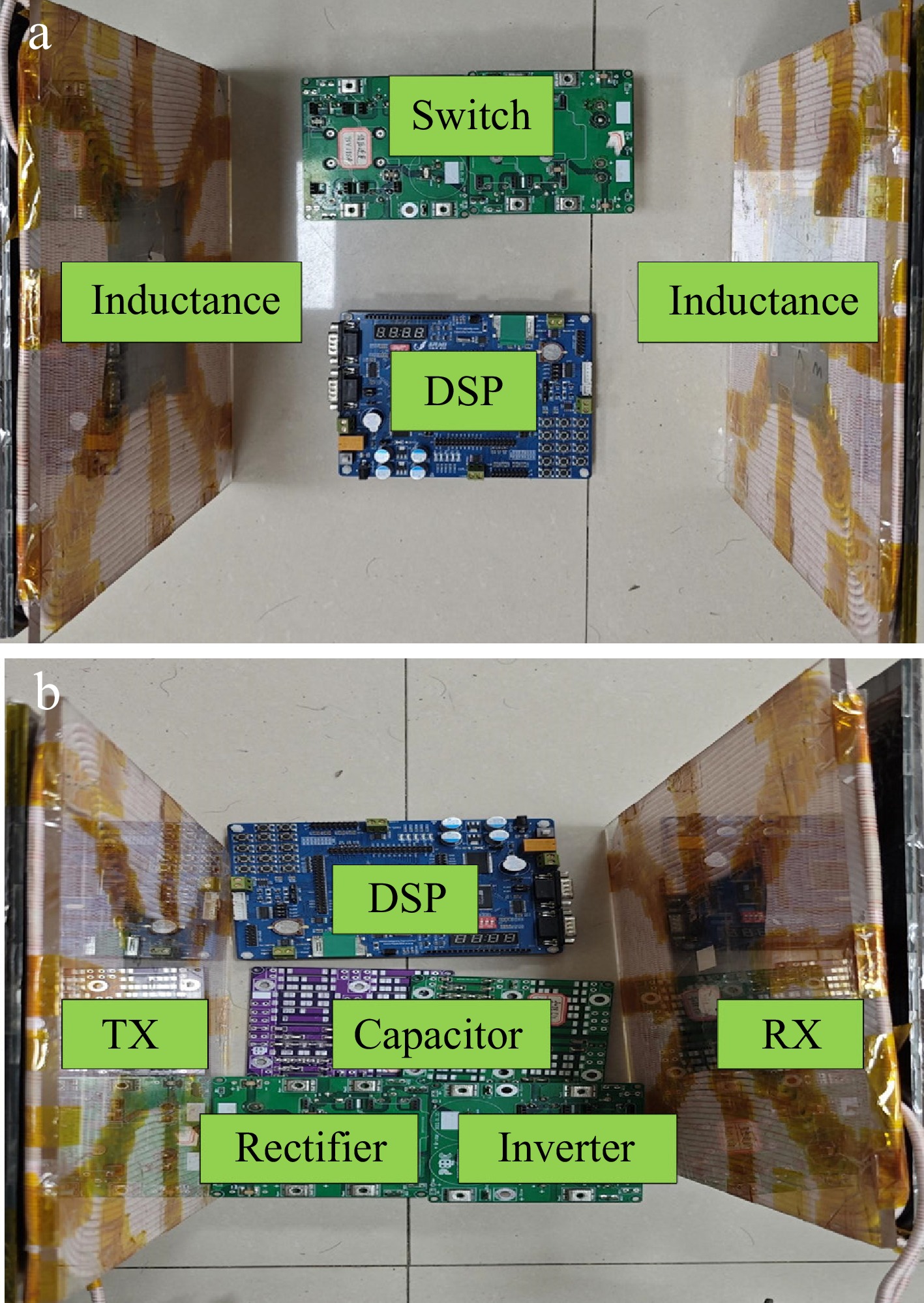
Figure 6.
Experimental prototypes. (a) Wired charging mode. (b) Wireless charging mode.
Table 1. Parameters of experimental prototype.
Charging mode parameters Wired L1 (μH) 186.01 L2 (μH) 180.57 V11 (V) 300.00 V12 (V) 230.00 D1 0.80 f (kHz) 85.00 Wireless L1 (μH) 191.09 L2 (μH) 193.92 M (μH) 52.82 k 0.27 C1 (nF) 18.20 C2 (nF) 18.14 V1 (V) 230.00 D2 0.25 f (kHz) 85.00 Wired charging mode
-
In the wired charging mode, RL ranges from 20 to 60 Ω. The calculated and experimental results of the output voltage and efficiency are depicted in Fig. 7.
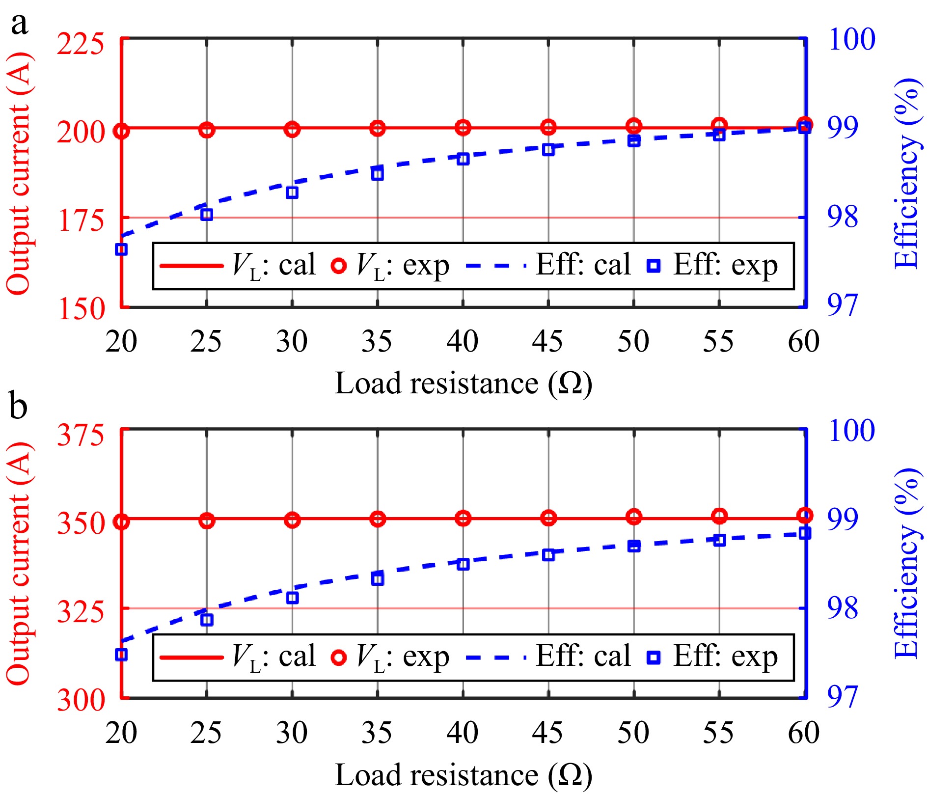
Figure 7.
Calculated and experimental results of wired charging mode. (a) Buck converter. (b) Boost converter.
For the buck converter, the output voltage has a fluctuation coefficient of 0.44% over the entire range of load variation, indicating that the converter has good CV output characteristics. The efficiency of the buck converter increases from 97.6% to 98.9% as the load increases, indicating a positive correlation between efficiency and load.
The boost converter demonstrates an output voltage fluctuation coefficient of less than 0.14% across the range of load variations, indicating stable CV output characteristics. The efficiency of the boost converter also increases with the load. It increases from 97.5% to 98.8%, indicating a positive correlation between the efficiency and the load.
The efficiency of the wired charging mode is positively related to the load. The reason for this may be that the total losses under heavier loads decrease as a percentage of the system power.
Wireless charging mode
-
In the wireless charging mode, RL ranges from 20 to 60 Ω. The output current and the efficiency are illustrated in Fig. 8. The output current under the two input voltages decreases with the increase of load, and the fluctuation coefficients are 3.6% and 3.4% over the whole load variation range, respectively, indicating that the system output current characteristics are stable. The efficiency of the wireless charging mode increases from loads of 20 to 30 Ω, reaching its peak at 30 Ω, and subsequently decreases. This likely occurs because the optimal load for the system is approximately 30 Ω, where system losses are minimized as a proportion of output power, leading to maximum efficiency.
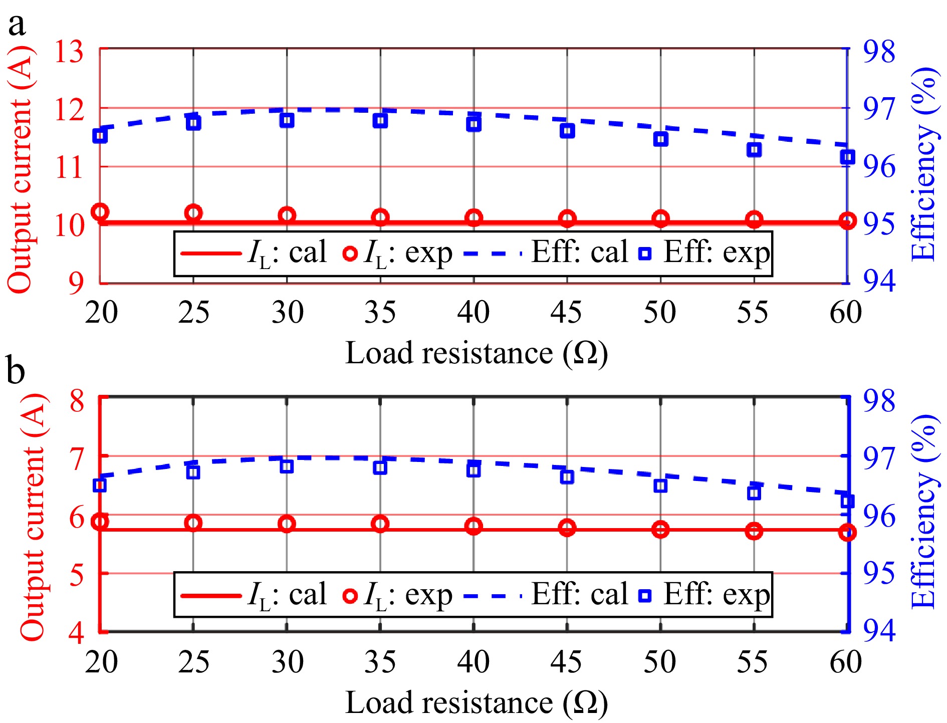
Figure 8.
Calculated and experimental results of wireless charging mode. (a) V1 = 350 V. (b) V1 = 200 V.
-
This paper has proposed a hybrid wired and wireless V2V charging system suitable for emergency charging. The wireless charging mode can improve the safety and convenience of the charging process without additional connecting wires, but it requires the coils to be aligned and is suitable for use in bad weather. The wired charging mode, which requires additional connecting wires but has no requirement on the relative position of the EVs, can be used for different models of EVs because it provides wider voltage gain and higher transmission efficiency. The S-S resonant topology, which can be transformed into a bidirectional DC-DC converter for wired charging mode, is adopted in wireless charging mode. The mathematical models and the experimental prototypes have been constructed. The proposed V2V system can realize stable CV output in wired charging mode and CC output in wireless charging mode. The efficiency of the wired charging mode is higher than 97% and the efficiency of the wireless charging mode is higher than 96%. The experimental results confirm the competitiveness of this proposal as a solution for wireless charging in V2V applications. In comparison to existing V2V systems, the proposed V2V system is capable of being reconfigured into wired and wireless charging modes straightforwardly and cost-effectively, which is suitable for a variety of charging conditions.
This work was supported in part by the National Natural Science Foundation of China (52407197, 52107183) and in part by the Natural Science Foundation of Fujian Province (2022J06011).
-
The authors confirm contribution to the paper as follows: study conception and design: Zhang Y, Xie R; data collection: Xie R, Liu Q; analysis and interpretation of results: Zhang Y, Xie R; draft manuscript preparation: Xie R, Liu Q, Chen Y, Shi J, Yue J, Lin G, Chen X, Zhang Y. All authors reviewed the results and approved the final version of the manuscript.
-
The datasets generated during and/or analyzed during the current study are available from the corresponding author on reasonable request.
-
The authors declare that they have no conflict of interest. Yiming Zhang is the Editorial Board member of Wireless Power Transfer who was blinded from reviewing or making decisions on the manuscript. The article was subject to the journal's standard procedures, with peer-review handled independently of this Editorial Board member and the research groups.
- Copyright: © 2024 by the author(s). Published by Maximum Academic Press, Fayetteville, GA. This article is an open access article distributed under Creative Commons Attribution License (CC BY 4.0), visit https://creativecommons.org/licenses/by/4.0/.
-
About this article
Cite this article
Xie R, Liu Q, Chen Y, Shi J, Yue J, et al. 2024. A simple integrated solution of reconfigurable wired and wireless Vehicle-to-Vehicle (V2V) charging system. Wireless Power Transfer 11: e011 doi: 10.48130/wpt-0024-0013 

A simple integrated solution of reconfigurable wired and wireless Vehicle-to-Vehicle (V2V) charging system
- Received: 06 August 2024
- Revised: 20 September 2024
- Accepted: 25 October 2024
- Published online: 21 November 2024
Abstract: To cope with different charging conditions, a hybrid wired and wireless vehicle-to-vehicle (V2V) charging system is proposed. The series-series (S-S) resonant topology is adopted for the wireless charging mode. It can be transformed into a bidirectional DC-DC converter for the wired charging mode. A simple circuit connection and switching pattern can achieve this target. Mathematical models of the two modes are developed and system configurations in the corresponding modes are explored. Two experimental prototypes are implemented to validate the proposal. Compared with the existing V2V systems, the proposed V2V system can be reconfigured into wired and wireless charging modes simply and cost-effectively, making it suitable for various charging conditions.
-
Key words:
- Wireless power transfer /
- Vehicle-to-vehicle /
- Integrated /
- DC-DC converter