-
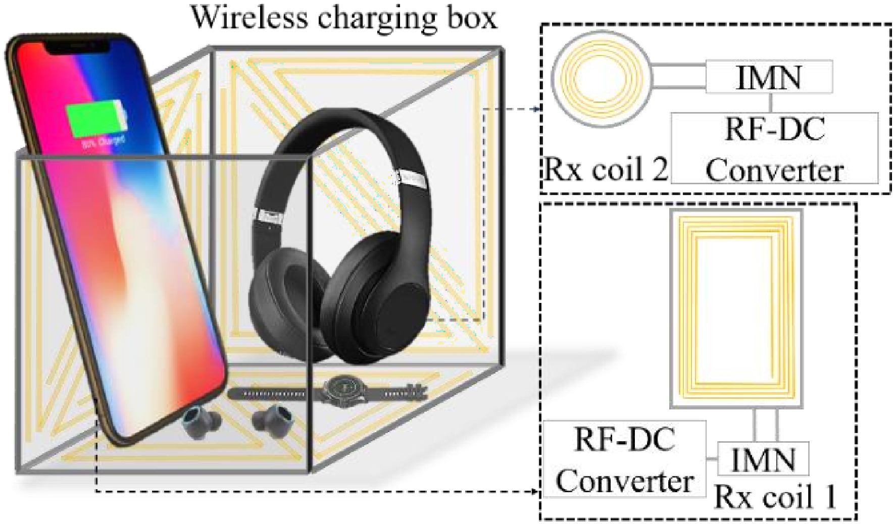
Figure 1.
Free-positioning for multiple-receivers WPT system.
-
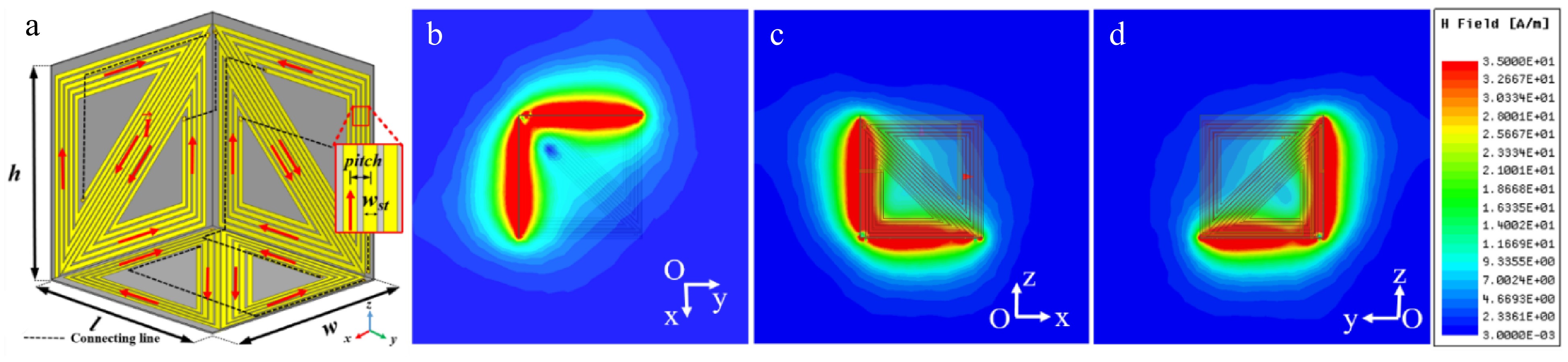
Figure 2.
(a) Proposed HCS-Tx coil: l = 116 mm, w = 116 mm, and h = 116 mm. (b)−(d) Magnetic field distribution on Oxy, Oxz, and Oyz planes.
-
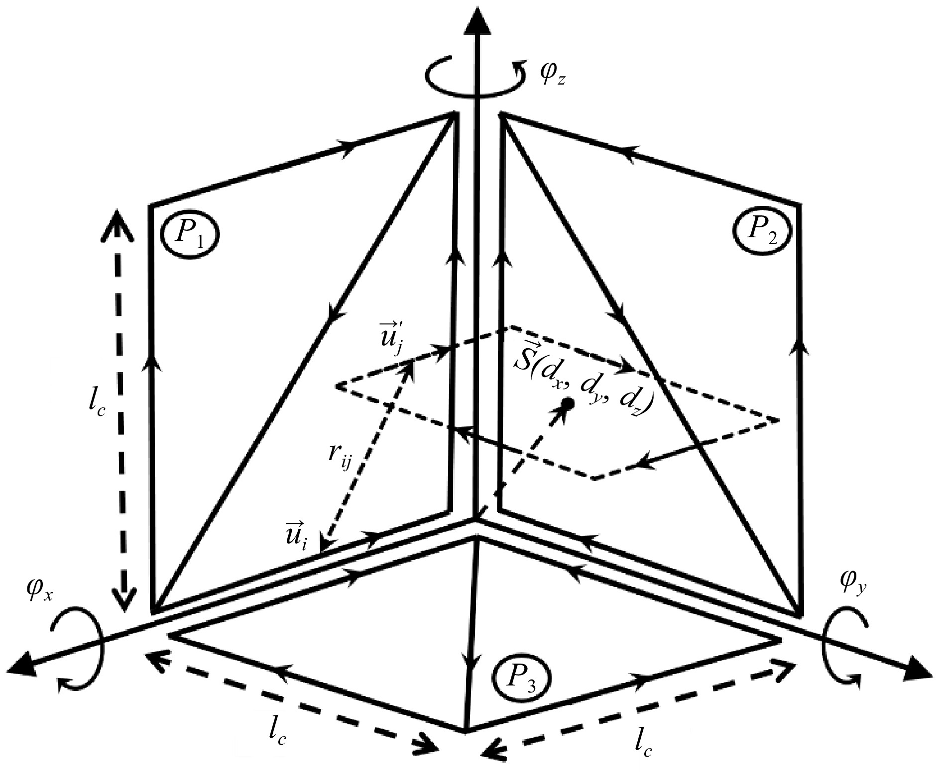
Figure 3.
Schematic illustration of the free-positioning WPT system.
-
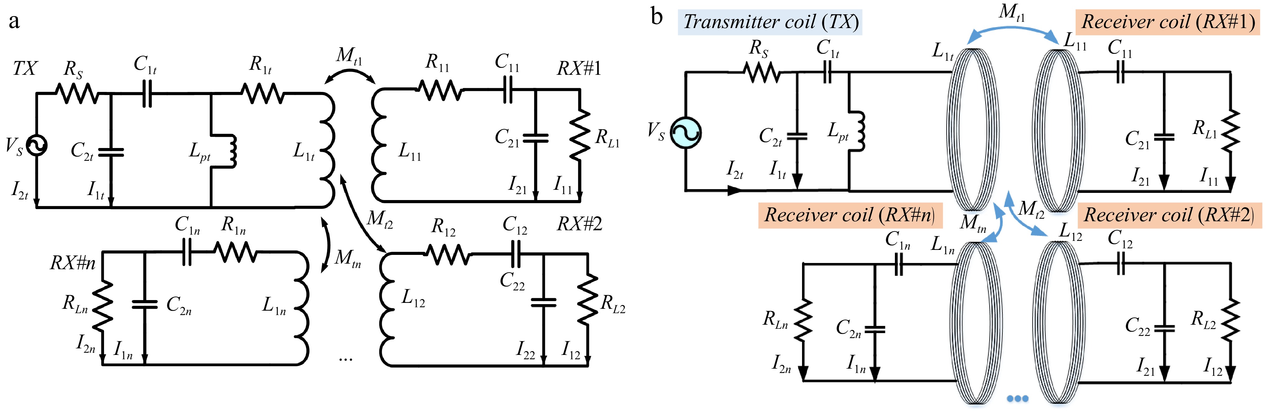
Figure 4.
(a) Multiple-receivers WPT equivalent circuit. (b) Structural diagram of Multiple-receivers WPT.
-
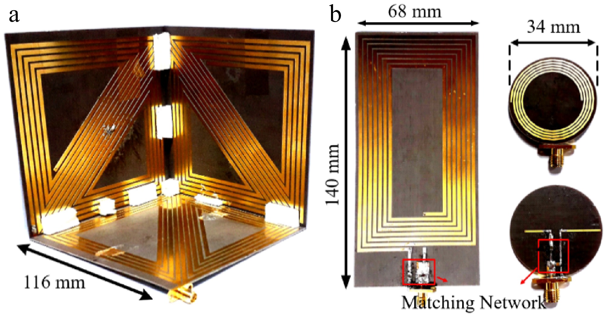
Figure 5.
(a) Fabricated HCS-Tx coil, (b) rectangular Rx coil, and (c) circular Rx coil.
-
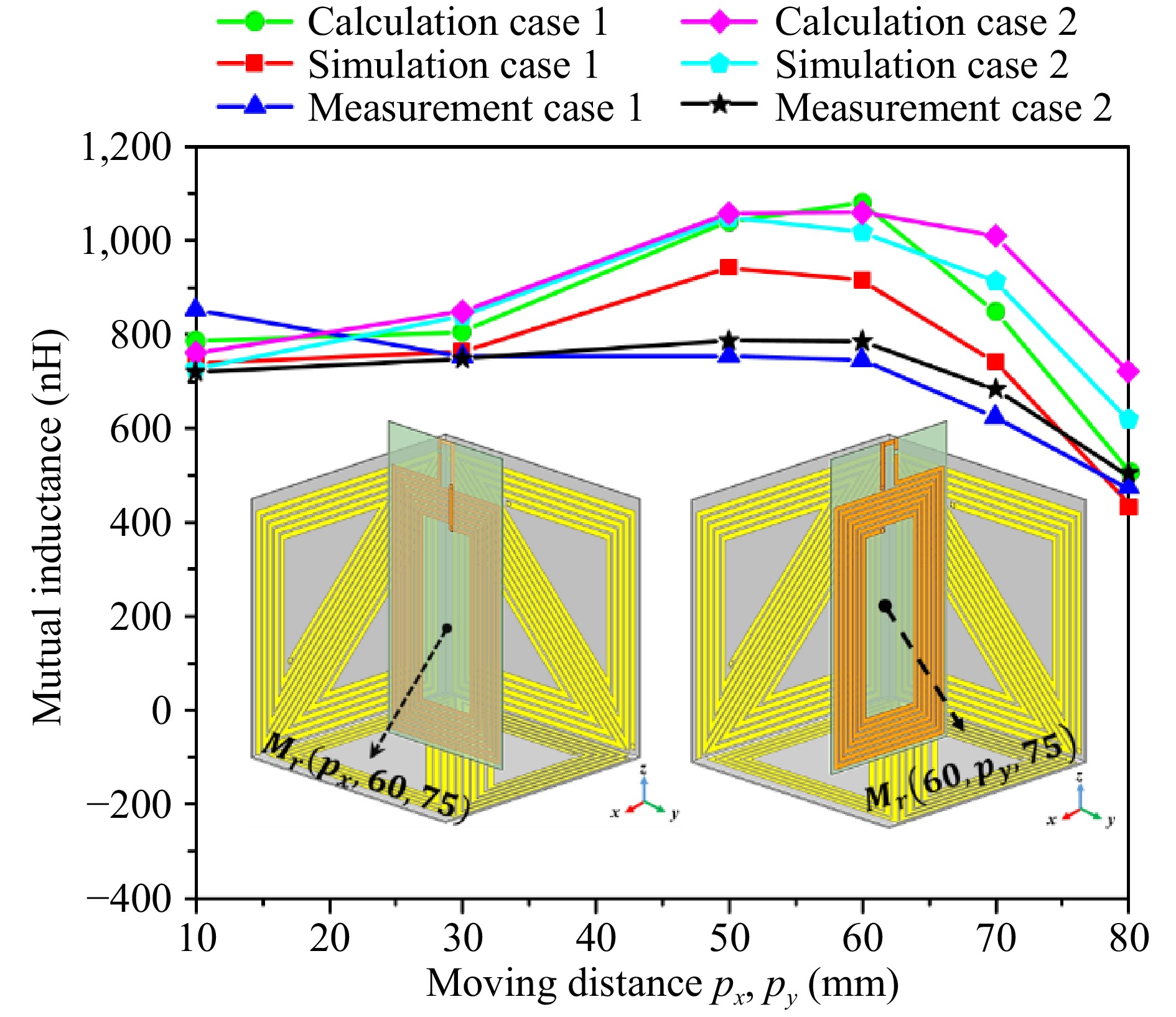
Figure 6.
Mutual inductance between the HCS-Tx coil and rectangular Rx coil.
-
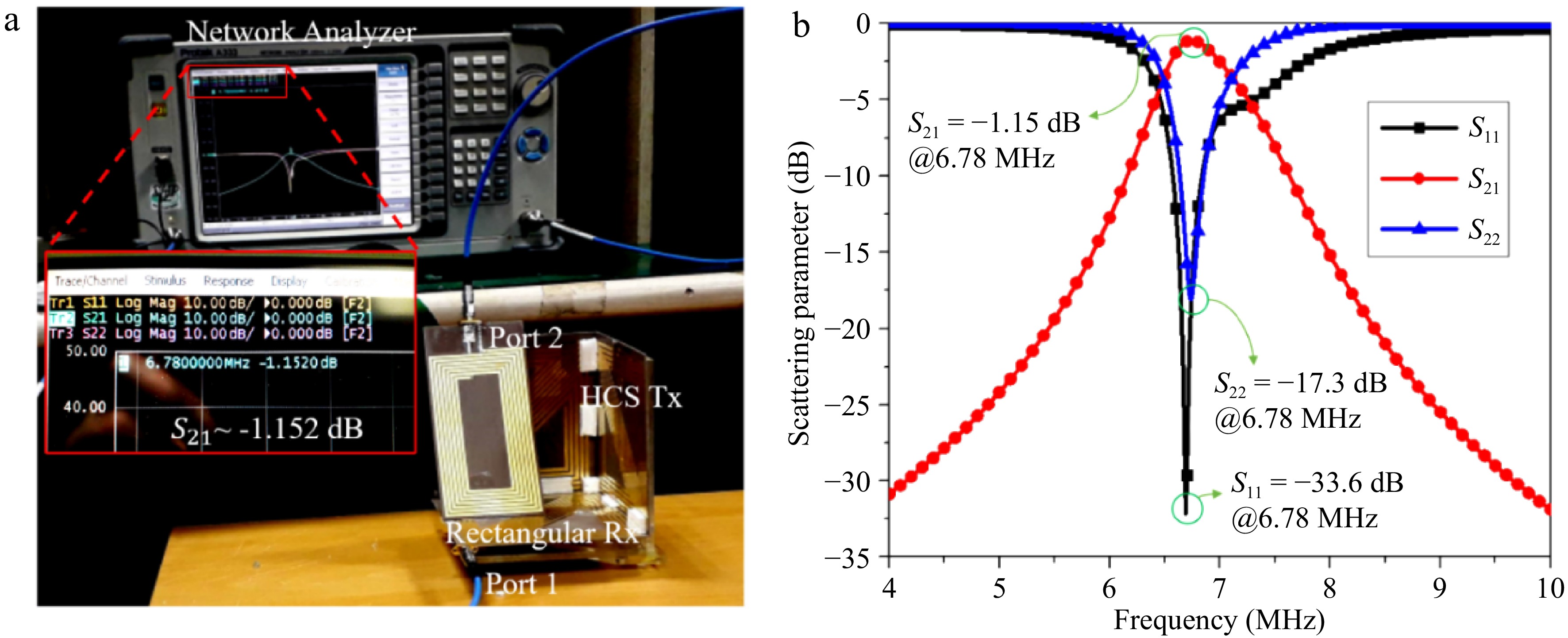
Figure 7.
(a) Single receiver WPT system measurement. (b) S-parameter results.
-
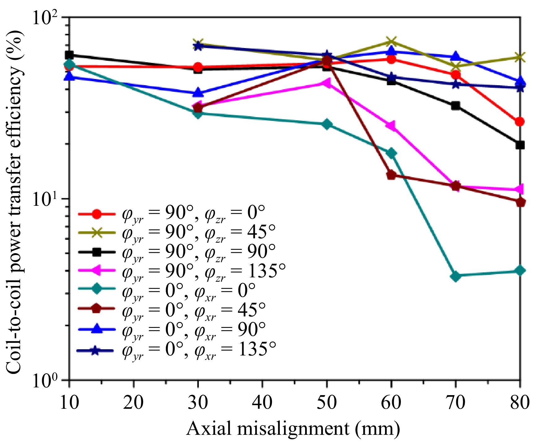
Figure 8.
Coil-to-coil power transfer efficiency.
-
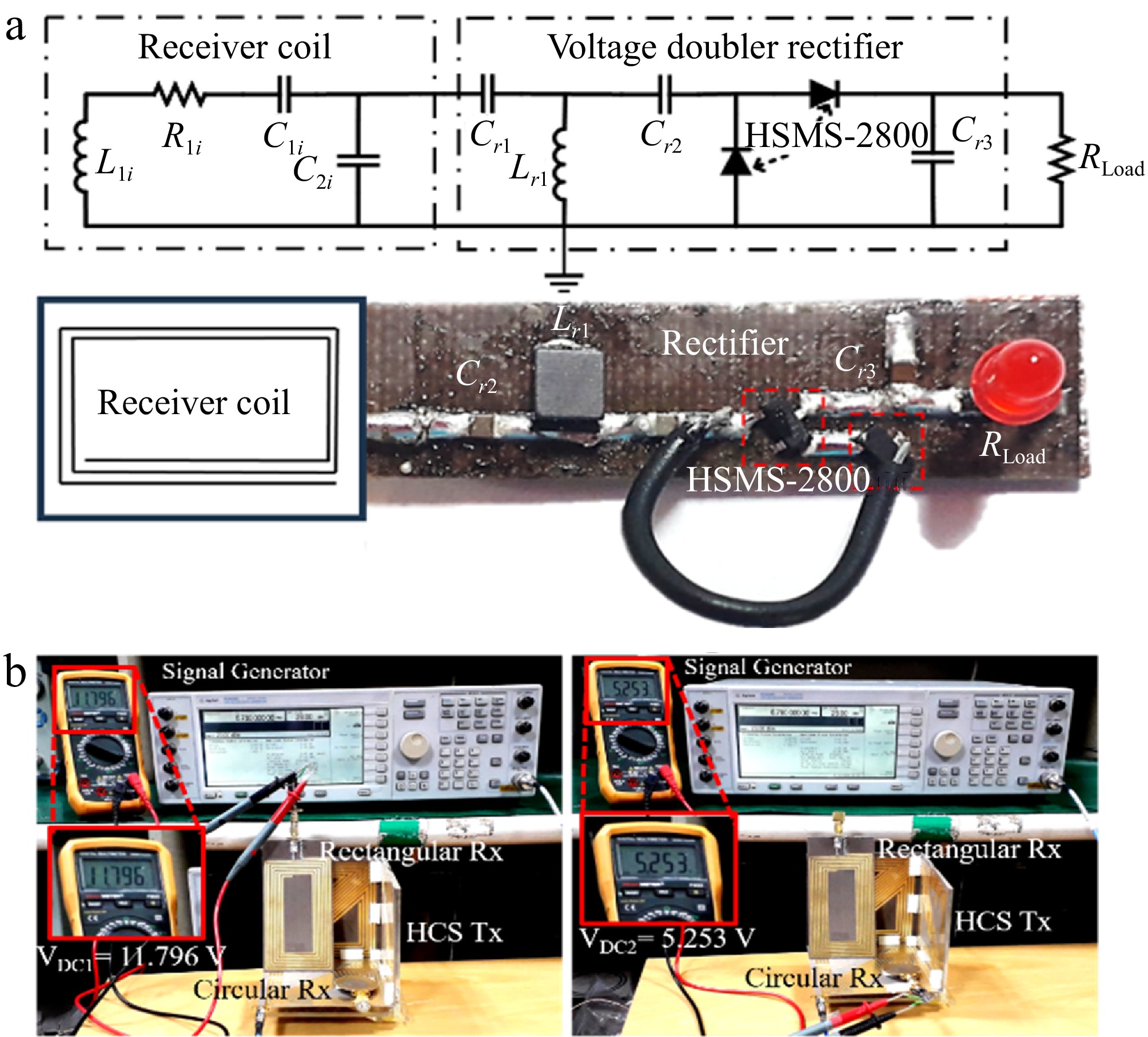
Figure 9.
(a) Schematic diagram of Rx circuit: Cr1 = 150 pF, Lr1 = 3.3 μH, Cr2 = 130 pF, Cr3 = 1 F, RLoad = 1.3 kΩ. (b) Experimental setup for the multiple-receivers wireless charging system with the positions of Rx coil represented by dxr = 82 mm, dyr = 14 mm, dzr = 65 mm, φxr = φyr = φzr = 0°, dxc = 80 mm, dyc = 40 mm, dzc = 5 mm, φxc = φyc = φzc = 0°.
-
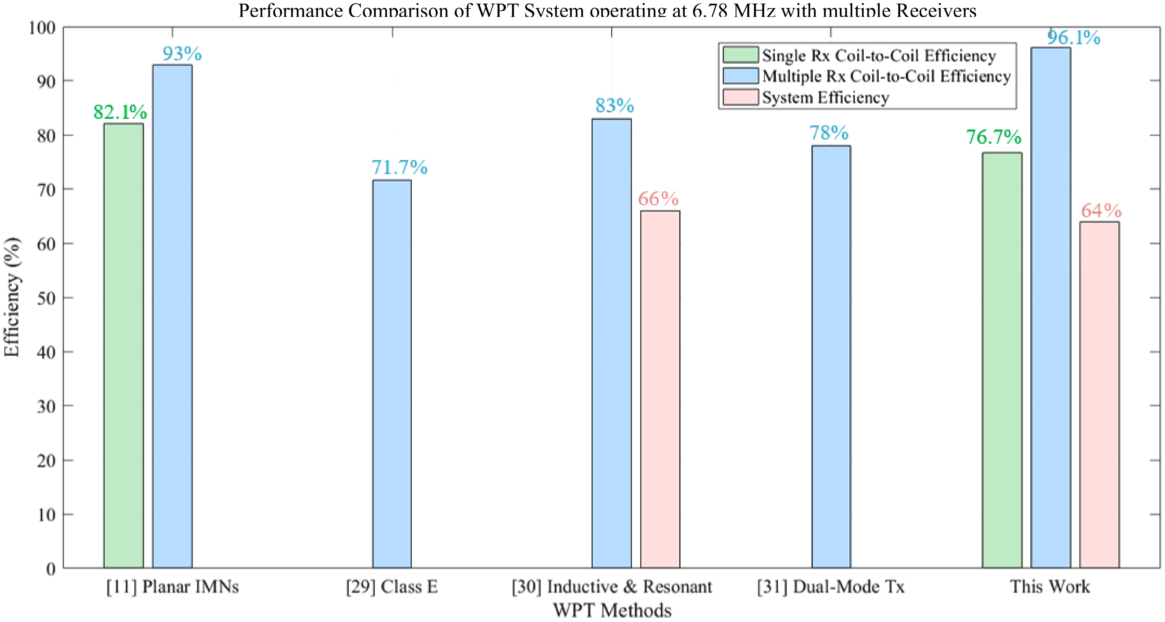
Figure 10.
Performance comparison of wireless power transfer (WPT) systems operating at 6.78 MHz with multiple receivers.
-
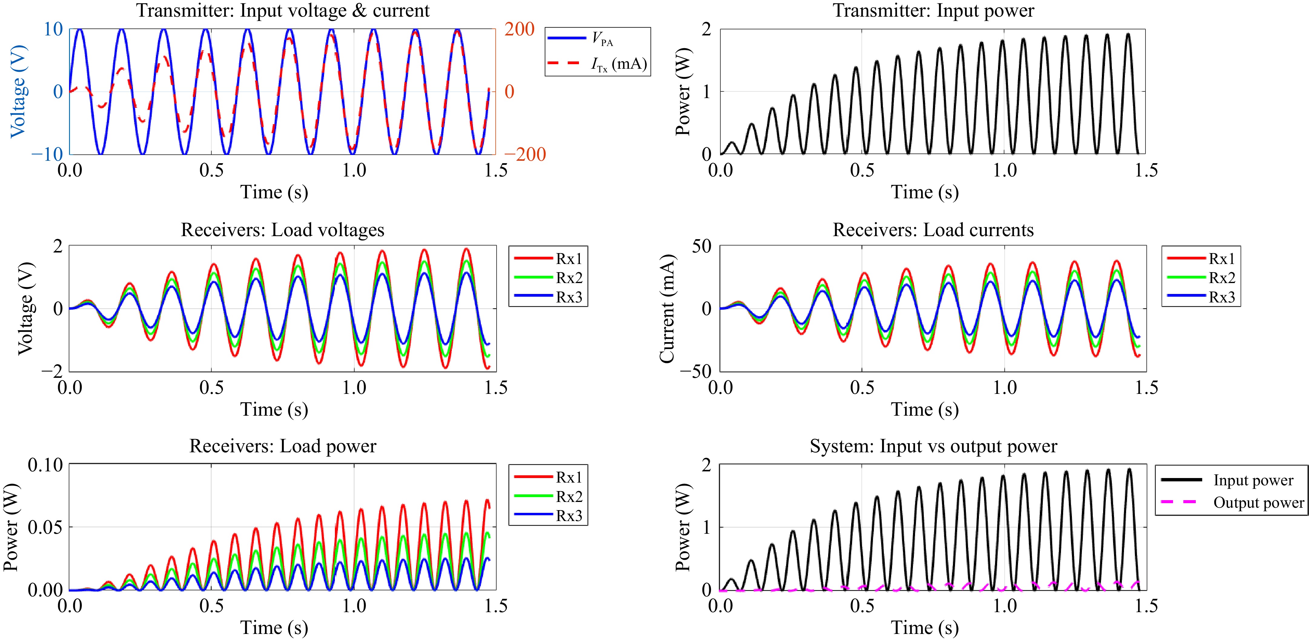
Figure 11.
Waveform diagram to illustrate the relationship between electrical parameters.
-
FP HCS Tx Rectangular Rx Circular Rx Parameter Value Parameter Value Parameter Value L1t 25.56 μH L11 6 μH L12 1.07 μH R1t 36 Ω R11 2.36 Ω R12 0.67 Ω Lpt 8.2 μH C11 100 pF C12 655 pF C1t 85 pF C21 1 nF C22 2.4 nF C2t 1 pF RL1 50 Ω RL2 50 Ω RS 50 Ω Table 1.
Extracted lumped element values.
-
Rectangular Rx Circular Rx Overall PTE Coordinate (mm) Angle (°) PTE Coordinate (mm) Angle (°) PTE dxr dyr dzr φxr φyr φzr dxc dyc dzr φxc φyc φzc 82 26 60 65 0 0 74.13% 35 85 5 0 0 0 20.42% 94.55% 82 26 60 65 0 0 73.79% 5 35 35 0 90 0 22.35% 96.14% 82 26 60 65 0 0 74.64% 5 80 80 0 90 0 20.42% 95.06% 82 14 65 70 0 0 65.77% 80 40 5 0 0 0 20.42% 86.19% 82 14 65 70 0 0 70.79% 80 40 5 0 0 0 22.38% 93.18% Table 2.
Summary of measured power transfer efficiency of multiple-receivers WPT system.
-
WPT method Resonant
frequency (MHz)Coil-to-coil transmission efficiency System efficiency Ref. Single Rx Multiple Rx Planar Tx coil with switchable IMNs 6.78 82.1% 93% NG [11] Class E amplifier with multiple receivers 6.78 NG 71.7% NG [29] WPT system for multiple receivers operating at Inductive and Resonant Operating Modes 6.78 NG 83% 66% [30] WPT system for a dual-mode transmitter, along with two receivers 6.78 NG 78% NG [31] Printed spiral half-cube shaped Tx structure 6.78 76.74% 96.14% 64% This work Table 3.
Performance Comparison of wireless power transfer (WPT) systems operating at 6.78 MHz with multiple receivers.
Figures
(11)
Tables
(3)