


-
Wireless power transfer (WPT) offers a practical and efficient method for delivering energy to electronic devices across various applications, including electric vehicles, medical implants, and consumer electronics[1−7]. With the rapid increase of portable devices, there is a growing need to design wireless charging systems that can simultaneously power multiple devices[8−10]. To achieve this, multiple-receiver (Rx) WPT systems have been explored to address system issues, including impedance-matching networks, and cross-coupling effects[11−15]. However, receiving devices often vary in dimensions, positions, and orientations. Free-positioning WPT offers a promising solution for reliable wireless charging of multiple devices, regardless of their arrangement or position[11,16−20]. This advancement enables more flexible deployment in everyday applications, eliminating the need for precise receiver positioning. It enhances the practicality of wireless charging in environments where mobility and spatial freedom are essential.
One proposed approach involves a bowl-shaped transmitter (Tx) structure designed to wirelessly charge a hearing aid[16]. This design, however, presents limitations, as it generates a narrow dead-zone near the center of the Tx coil in perpendicular arrangements. Another free-positioning Tx design, a half-rectangular prism structure has been proposed for consumer applications. While it reduces dead-zone issues, it still leaves a dead-zone at planes angled at 45° between adjacent coils[17]. Alternatively, controllable impedance matching networks have been proposed to achieve optimal power transfer efficiency (PTE) by automatically adjusting lumped element values[21−24]. However, the complexity of the control system poses challenges for practical implementation.
Figure 1 illustrates a typical free-positioning WPT system scenario for multiple devices. The consumer devices are placed freely inside the charging box, which is embedded in a Tx coil. The various Rx coils are based on the actual device shapes and designed with the impedance matching networks (IMN), and the RF-DC converters.
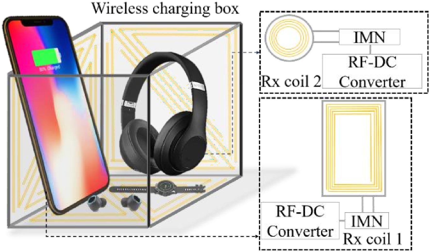
Figure 1.
Free-positioning for multiple-receivers WPT system.
In this paper, we present a free-positioning WPT system for multiple-receiver applications. A half-cube-shaped Tx (HCS-Tx) structure is proposed whose field distribution analysis reveals robust and strong magnetic fields in the charging area. Moreover, two distinct receiver (Rx) configurations are adapted to evaluate the system's spatial performance. The mutual inductance between the HCS transmitter (Tx) and a moving receiver is determined through a mathematical approach. Circuit theory is employed to analyze the wireless power transfer (WPT) system with multiple receivers, deriving a generalized power transfer efficiency (PTE) function. An LCC matching network aligns the impedance of arbitrary coils with the source and load impedances. Both the Tx and Rx coils operate at 6.78 MHz, a frequency selected from the Industrial, Scientific, and Medical (ISM) radio bands.
The proposed design overcomes the limitations seen in previous systems, and lays the groundwork for a flexible, efficient, and scalable WPT framework suitable for diverse real-world applications.
The system fabrication and experiment is implemented to verify the PTE of the single Rx, as well as the multiple-receiver WPT system. A multiple-receiver wireless charging system is implemented with a double voltage rectifier. The overall system efficiency is evaluated depending on the input RF power, which presents a good performance of the multiple-receiver wireless charging system.
-
In a magnetic resonant coupling WPT system, the efficiency of power transfer between coils is assessed by mutual inductance and the impedance matching network (IMN). The mutual inductance has been evaluated by the coil configuration and arrangement, which is significantly changed by varying the Rx position or rotating the Rx around its axis. Moreover, the coupling between two adjacent coils has also been decided by the magnetic flux with a stronger magnetic intensity, creating a higher mutual inductance. Therefore, the Rx coil will couple sufficiently with the Tx coil if it is placed in a strong magnetic field region. For a free-positioning WPT system, the Tx structure has been expected to generate a uniformly strong magnetic field to guarantee an effective power transfer on various positions of the Rx coil. To improve power delivery consistency, advanced coil arrangements, and field-shaping techniques can be utilized to maintain strong coupling across diverse Rx positions. Adaptive impedance matching further stabilizes system performance under varying load and alignment conditions. These strategies collectively support efficient and reliable multi-receiver operation in free-positioning WPT systems.
Free-positioning half-cube-shaped transmitter
-
To obtain a free-positioning power transfer, the produced magnetic field of the Tx coil has been required to achieve a strongly coupled magnetic field between Tx and Rx coils in the charging area. The HCS-Tx has been proposed with three orthogonal sub-coil planes, as shown in Fig. 2a. Each sub-coil plane consists of two triangular coil loops replacing the conventional rectangular coil to avoid the power-null point without using any additional compensation circuit[25−28]. In order to adapt the Rx rotation, the flowing current direction on each sub-coil plane is physically controlled as shown in Fig. 2a. Two consecutive sub-coils are connected by the connecting line on the bottom side of HCS-Tx. In addition, the current directions on two parallel coils have been arranged as identical to prevent the magnetic field elimination. The total magnetic field of the Tx coil has been increasingly contributed by the field elements generated from the sub-coils. Figure 2b−d illustrates the magnetic field distribution on three corresponding Cartesian coordinates of the HCS-Tx coil in Oxy, Oyz, and Ozx planes. The field pattern on each plane represents a strong magnetic field intensity that covers most of the Tx cross-sectional area. The printed spiral coil has been used to constitute the HCS-Tx structure due to its compact characteristics. The magnetic field intensity is also decided by the number of turns, coil width, and the coil pitch respectively. For the proposed HCS-Tx coil structure, the five-turn triangular coil has been designed with a coil width wst of 2.5 mm, and the coil pitch of 3.8 mm to obtain a strong magnetic field and low intrinsic resistance.
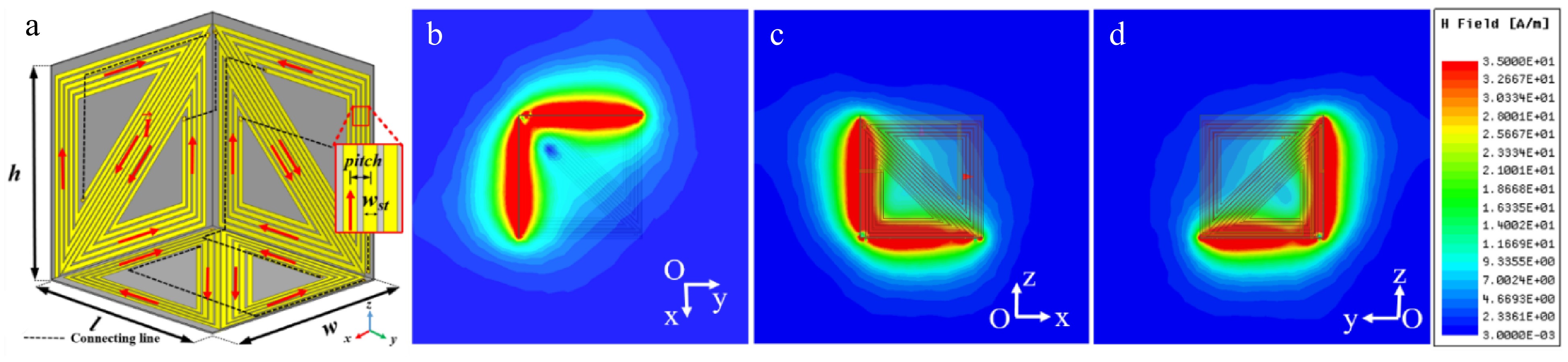
Figure 2.
(a) Proposed HCS-Tx coil: l = 116 mm, w = 116 mm, and h = 116 mm. (b)−(d) Magnetic field distribution on Oxy, Oxz, and Oyz planes.
Calculation of mutual inductance
-
The mutual inductance between two wires is determined by evaluating Neumann's integral equation:
$ {\mathrm{M}}_{12}=\left(\dfrac{{{\mu }}_{0}}{4{\text{π}}}\right){\oint }_{{\mathrm{L}}_{\mathrm{t}}}{\oint }_{{\mathrm{L}}_{\mathrm{r}}}\dfrac{\mathrm{d}{\vec{\mathrm{l}}}_{\mathrm{t}}\mathrm{d}{\vec{\mathrm{l}}}_{\mathrm{r}}}{\mathrm{r}} $ (1) where, Lt and Lr depict the Tx and Rx coil,
$ \mathrm{d}{\vec{\mathrm{l}}}_{\mathrm{t}} $ $ \mathrm{d}{\vec{\mathrm{l}}}_{\mathrm{r}} $ The HCS-Tx structure is modeled to three square coil planes with each coil turn represented as a thin wire structure, as shown in Fig. 3. The coil plane dimensions are identical and determined by the coil length lc. The ith coil turn is described by a vector
$ {\vec{\mathrm{u}}}_{\mathrm{i}} $ 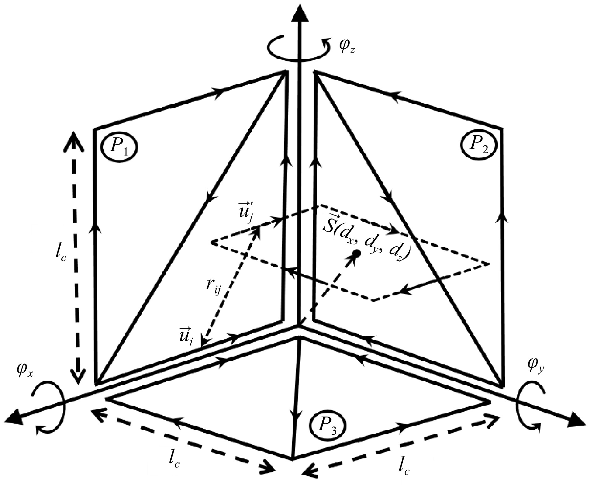
Figure 3.
Schematic illustration of the free-positioning WPT system.
The Rx coil, on the other hand, is divided into straight segments, each of which is denoted by a vector
$ {\vec{\mathrm{u}}}_{\mathrm{j}} $ $ {\mathrm{M}}_{\mathrm{i}\mathrm{j}}=\dfrac{{{\mu }}_{0}}{4{\text{π}}}\sum _{\mathrm{i}=1}^{{\mathrm{C}}_{\mathrm{i}}}\sum _{\mathrm{j}=1}^{{\mathrm{C}}_{\mathrm{j}}}\dfrac{{\vec{\mathrm{u}}}_{\mathrm{i}}\cdot{\vec{\mathrm{u}}}_{\mathrm{j}}}{{\mathrm{r}}_{\mathrm{i}\mathrm{j}}} $ (2) where, Ci denotes the number of vectors on Tx and Cj denote the number of vectors on Rx, and rij represents the distance between two vectors. The mutual inductance is investigated when moving Rx freely inside Tx to verify the stability of the mutual inductance value. The reference coordinate is illustrated by the coordinate variation of Rx center point. Specifically, the Cartesian movement is represented by
$ \overrightarrow{\mathrm{S}} $ $ {\vec{\mathrm{u}}}_{\mathrm{j}} $ $ {\vec{\mathrm{u}}}_{\mathrm{j}}^{{{'}}}\left({\mathrm{x}}_{\mathrm{j}}^{{{'}}},{\mathrm{y}}_{\mathrm{j}}^{{{'}}},{\mathrm{z}}_{\mathrm{j}}^{{{'}}}\right) $ $\begin{aligned} & {\mathrm{M}}_{{\mathrm{P}}_{1}|\mathrm{R}\mathrm{x}}=\dfrac{{{\mu }}_{0}}{4{\text{π}}}{\sum }_{\mathrm{j}=1}^{{\mathrm{C}}_{\mathrm{j}}} \;\times \\ & \left[\dfrac{2{\mathrm{l}}_{\mathrm{c}}{\mathrm{z}}_{\mathrm{j}}^{{{'}}}}{\sqrt{{{\mathrm{x}}_{\mathrm{j}}^{{{'}}}}^{2} +{{\mathrm{y}}_{\mathrm{j}}^{{{'}}}}^{2} +{\left({\mathrm{l}}_{\mathrm{c}} -{\mathrm{z}}_{\mathrm{j}}^{{{'}}}\right)}^{2}}}-\dfrac{2{\mathrm{l}}_{\mathrm{c}}{\mathrm{x}}_{\mathrm{j}}^{{{'}}}}{\sqrt{{\left({\mathrm{l}}_{\mathrm{c}} -{\mathrm{x}}_{\mathrm{j}}^{{{'}}}\right)}^{2} +{{\mathrm{y}}_{\mathrm{j}}^{{{'}}}}^{2} +{{\mathrm{z}}_{\mathrm{j}}^{{{'}}}}^{2}}}+\dfrac{{\mathrm{l}}_{\mathrm{c}}{\mathrm{x}}_{\mathrm{j}}^{{{'}}} -{\mathrm{l}}_{\mathrm{c}}{\mathrm{z}}_{\mathrm{j}}^{{{'}}}}{\sqrt{{\left({\mathrm{l}}_{\mathrm{c}} -{\mathrm{x}}_{\mathrm{j}}^{{{'}}}\right)}^{2} +{{\mathrm{y}}_{\mathrm{j}}^{{{'}}}}^{2} +{\left({\mathrm{l}}_{\mathrm{c}} -{\mathrm{z}}_{\mathrm{j}}^{{{'}}}\right)}^{2}}}\right] \end{aligned}$ (3) $ \begin{aligned} & {\mathrm{M}}_{{\mathrm{P}}_{2}|\mathrm{R}\mathrm{x}}=\dfrac{{{\mu }}_{0}}{4{\text{π}}}{\sum }_{\mathrm{j}=1}^{{\mathrm{C}}_{\mathrm{j}}} \;\times \\ & \left[\dfrac{2{\mathrm{l}}_{\mathrm{c}}{\mathrm{z}}_{\mathrm{j}}^{{{'}}}}{\sqrt{{{\mathrm{x}}_{\mathrm{j}}^{{{'}}}}^{2} +{{\mathrm{y}}_{\mathrm{j}}^{{{'}}}}^{2} +{\left({\mathrm{l}}_{\mathrm{c}} -{\mathrm{z}}_{\mathrm{j}}^{{{'}}}\right)}^{2}}}-\dfrac{2{\mathrm{l}}_{\mathrm{c}}{\mathrm{y}}_{\mathrm{j}}^{{{'}}}}{\sqrt{{{\mathrm{x}}_{\mathrm{j}}^{{{'}}}}^{2} +{\left({\mathrm{l}}_{\mathrm{c}} -{\mathrm{y}}_{\mathrm{j}}^{{{'}}}\right)}^{2} +{{\mathrm{z}}_{\mathrm{j}}^{{{'}}}}^{2}}}+\dfrac{{\mathrm{l}}_{\mathrm{c}}{\mathrm{y}}_{\mathrm{j}}^{{{'}}}-{\mathrm{l}}_{\mathrm{c}}{\mathrm{z}}_{\mathrm{j}}^{{{'}}}}{\sqrt{{{\mathrm{x}}_{\mathrm{j}}^{{{'}}}}^{2} +{\left({\mathrm{l}}_{\mathrm{c}} -{\mathrm{y}}_{\mathrm{j}}^{{{'}}}\right)}^{2} +{\left({\mathrm{l}}_{\mathrm{c}} -{\mathrm{z}}_{\mathrm{j}}^{{{'}}}\right)}^{2}}}\right] \end{aligned}$ (4) $ \begin{aligned} & {\mathrm{M}}_{{\mathrm{P}}_{3}|\mathrm{R}\mathrm{x}}=\dfrac{{\mathrm{\mu }}_{0}}{4{\text{π}}}{\sum }_{\mathrm{j}=1}^{{\mathrm{C}}_{\mathrm{j}}} \;\times \\ & \left[-\dfrac{2{\mathrm{l}}_{\mathrm{c}}{\mathrm{x}}_{\mathrm{j}}^{{{'}}}}{\sqrt{{\left({\mathrm{l}}_{\mathrm{c}} -{\mathrm{x}}_{\mathrm{j}}^{{{'}}}\right)}^{2} +{\mathrm{y}}_{\mathrm{j}}^{{{{'}}}^{2}} +{\mathrm{z}}_{\mathrm{j}}^{{{{'}}}^{2}}}}-\dfrac{2{\mathrm{l}}_{\mathrm{c}}{\mathrm{y}}_{\mathrm{j}}^{{{'}}}}{\sqrt{{\mathrm{x}}_{\mathrm{j}}^{{{{'}}}^{2}} +{\left({\mathrm{l}}_{\mathrm{c}} -{\mathrm{y}}_{\mathrm{j}}^{{{'}}}\right)}^{2} +{{\mathrm{z}}_{\mathrm{j}}^{{{'}}}}^{2}}}+\dfrac{{\mathrm{l}}_{\mathrm{c}}{\mathrm{x}}_{\mathrm{j}}^{{{'}}}-{\mathrm{l}}_{\mathrm{c}}{\mathrm{y}}_{\mathrm{j}}^{{{'}}}}{\sqrt{{\left({\mathrm{l}}_{\mathrm{c}} -{\mathrm{x}}_{\mathrm{j}}^{{{'}}}\right)}^{2} +{\left({\mathrm{l}}_{\mathrm{c}} -{\mathrm{y}}_{\mathrm{j}}^{{{'}}}\right)}^{2} +{{\mathrm{z}}_{\mathrm{j}}^{{{'}}}}^{2}}}\right] \end{aligned}$ (5) Table 1 presents key parameters, specific details, and essential components involved in the design and execution of circuits for the free-positioning wireless power transfer (WPT) system.
Table 1. Extracted lumped element values.
FP HCS Tx Rectangular Rx Circular Rx Parameter Value Parameter Value Parameter Value L1t 25.56 μH L11 6 μH L12 1.07 μH R1t 36 Ω R11 2.36 Ω R12 0.67 Ω Lpt 8.2 μH C11 100 pF C12 655 pF C1t 85 pF C21 1 nF C22 2.4 nF C2t 1 pF RL1 50 Ω RL2 50 Ω RS 50 Ω The total mutual inductance between the HCS-Tx and Rx coil can be computed by:
$ {\mathrm{M}}_{12}^{\mathrm{a}}={\mathrm{M}}_{{\mathrm{P}}_{1}|\mathrm{R}\mathrm{x}}+{\mathrm{M}}_{{\mathrm{P}}_{2}|\mathrm{R}\mathrm{x}}+{\mathrm{M}}_{{\mathrm{P}}_{3}|\mathrm{R}\mathrm{x}} $ (6) Power transfer efficiency formulation for multiple-receivers WPT system
-
Figure 4a shows the equivalent circuit and Fig. 4b represents the structural diagram of Multiple-receivers WPT. The equivalent Tx and Rx components are represented by their self-inductance L1x and intrinsic resistances R1x (x = t, 1, ..., n indicates the HCS-Tx coil and each Rx coil). The mutual inductance between the HCS-Tx coil and each Rx coil is presented by Mlx. The cross-coupling between each Rx coil is neglected due to its small value compared to the mutual inductance. The source and load impedance RX, RLi are 50 Ω (i = 1, 2, ..., n indicates the Rx coils). Because of the longer physical length, the HCS-Tx coil presents a high characteristic impedance compared with the Rx coils. The LCC matching circuit is implemented on the HCS-Tx side and comprises a parallel inductor Lpt to reduce the input coil impedance. A series capacitor C1t and a parallel capacitor C2t are used to create resonant frequency and align the input coil impedance to source impedance. Meanwhile, on the Rx side, only a series capacitor C1i and parallel capacitor C2i (i = 1, 2, ..., n) are used due to the lower intrinsic resistance and inductance. The Tx coil impedance is given by:
$ {\mathrm{Z}}_{\mathrm{T}\mathrm{x}}={\left(\dfrac{1}{\mathrm{j}\mathrm{\omega }{\mathrm{L}}_{1\mathrm{t}}}+\dfrac{1}{{\mathrm{R}}_{1\mathrm{t}}+\mathrm{j}\mathrm{\omega }{\mathrm{L}}_{1\mathrm{t}}}\right)}^{-1} $ (7) Thus, the total resistance and inductance on the Tx coil are given by:
$ {\mathrm{R}}_{1\mathrm{t}}^{'}=\mathrm{R}\mathrm{e}\left({\mathrm{Z}}_{\mathrm{T}\mathrm{x}}\right) $ (8) $ \mathrm{Z}^{'}_{\mathrm{L}_{1\mathrm{t}}}=\ \mathrm{i}\ \times\ \mathrm{I}\mathrm{m}\left(\mathrm{Z}_{\mathrm{T}\mathrm{x}}\right) $ (9) The input impedance of the Tx and Rx coils are:
$ {\mathrm{Z}}_{\mathrm{t}}={\mathrm{R}}_{1\mathrm{t}}^{'}+{\mathrm{Z}}_{{\mathrm{L}}_{1\mathrm{t}}}^{'} $ (10) $ {\mathrm{Z}}_{\mathrm{i}}={\mathrm{R}}_{1\mathrm{i}}+\frac{1}{\mathrm{j}\mathrm{\omega }{\mathrm{C}}_{1\mathrm{i}}}+\mathrm{j}\mathrm{\omega }{\mathrm{L}}_{1\mathrm{i}} $ (11) where, the component of Tx and the ith of Rx coil are indicated by t and i, respectively.
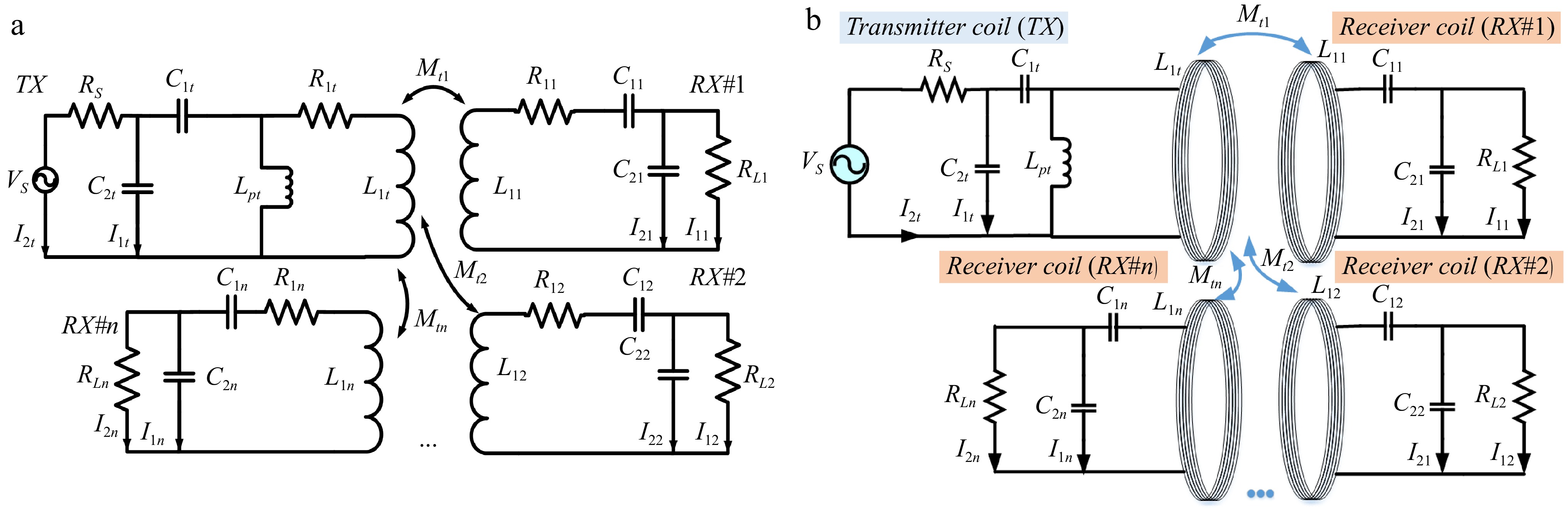
Figure 4.
(a) Multiple-receivers WPT equivalent circuit. (b) Structural diagram of Multiple-receivers WPT.
By using Kirchhoff's voltage law (KVL) on the Tx coil and reaching the Rx coil, the current relation between two arbitrary Rx coils is given by:
$ \mathrm{I}_{2\mathrm{j}}=\mathrm{I}_{2\mathrm{i}}\times\dfrac{\dfrac{\mathrm{Z}_{\mathrm{i}}}{\mathrm{Z}_{\mathrm{M}_{\mathrm{t}\mathrm{i}}}}\left(1+\dfrac{\mathrm{Z}_{\mathrm{C}_{2\mathrm{i}}}}{\mathrm{R}_{\mathrm{L}_{\mathrm{i}}}}+\dfrac{\mathrm{Z}_{\mathrm{C}_{2\mathrm{i}}}}{\mathrm{Z}_{\mathrm{i}}}\right)}{\dfrac{\mathrm{Z}_{\mathrm{j}}}{\mathrm{Z}_{\mathrm{M}_{\mathrm{t}\mathrm{j}}}}\left(1+\dfrac{\mathrm{Z}_{\mathrm{C}_{2\mathrm{j}}}}{\mathrm{R}_{\mathrm{L}_{\mathrm{j}}}}+\dfrac{\mathrm{Z}_{\mathrm{C}_{2\mathrm{j}}}}{\mathrm{Z}_{\mathrm{j}}}\right)} $ (12) The power transfer efficiency is also derived in Eq. (13), which is shown below. The resistance, capacitance, and inductance elements are given by:
$ \begin{aligned} \dfrac{{V}_{S}}{{V}_{L}}= &-\dfrac{{Z}_{{M}_{ti}}{R}_{S}}{{Z}_{{C}_{2t}}{Z}_{{C}_{2i}}}\left(1+\dfrac{{Z}_{{C}_{2i}}}{{R}_{Li}}\right)\left(1+\dfrac{{Z}_{{C}_{2t}}}{{R}_{S}}\right)\\ &+\dfrac{{R}_{S}}{{Z}_{{C}_{2i}}}\left(\dfrac{{Z}_{i}}{{Z}_{{M}_{ti}}}+\dfrac{{Z}_{i}{Z}_{{C}_{2i}}}{{Z}_{{M}_{ti}}{R}_{Li}}+\dfrac{{Z}_{{C}_{2i}}}{{Z}_{{M}_{ti}}}\right)\left(\dfrac{{Z}_{t}^{\text{'}}}{{Z}_{{C}_{2i}}}+\dfrac{{Z}_{t}^{\text{'}}{Z}_{{C}_{2t}}}{{R}_{S}{Z}_{{C}_{2i}}}+1\right)\\ &-\dfrac{{Z}_{i}{R}_{S}}{{Z}_{{M}_{ti}}{Z}_{{C}_{2t}}{Z}_{{C}_{2i}}}\left(1+\dfrac{{Z}_{{C}_{2i}}}{{R}_{Li}}+\dfrac{{Z}_{{C}_{2i}}}{{Z}_{i}}\right)\left(1+\dfrac{{Z}_{{C}_{2t}}}{{R}_{S}}\right)\\ &\times \sum _{j\ne i,j=i}^{n}\dfrac{1+\dfrac{{Z}_{{C}_{2j}}}{{R}_{{L}_{j}}}}{\dfrac{{Z}_{j}}{{Z}_{{M}_{tj}}^{2}}\left(1+\dfrac{{Z}_{{C}_{2j}}}{{R}_{{L}_{j}}}+\dfrac{{Z}_{{C}_{2j}}}{{Z}_{j}}\right)} \end{aligned}$ (13) $ {\mathrm{Z}}_{{\mathrm{C}}_{1\mathrm{t}}}=\dfrac{1}{\mathrm{j}\mathrm{\omega }{\mathrm{C}}_{1\mathrm{t}}};\;{\mathrm{Z}}_{{\mathrm{L}}_{1\mathrm{t}}}=\mathrm{j}\mathrm{\omega }{\mathrm{L}}_{1\mathrm{t}} $ (14) $ {\mathrm{Z}}_{{\mathrm{C}}_{1\mathrm{i}}}=\dfrac{1}{\mathrm{j}\mathrm{\omega }{\mathrm{C}}_{1\mathrm{i}}};\;{\mathrm{Z}}_{{\mathrm{C}}_{2\mathrm{i}}}=\dfrac{1}{\mathrm{j}\mathrm{\omega }{\mathrm{C}}_{2\mathrm{i}}} $ (15) The equivalent scattering parameter S21 and the corresponding PTE are calculated using Eq. (17):
$ \left|\mathrm{S}_{21}\right|=2\times\left|\dfrac{\mathrm{V}_{\mathrm{L}}}{\mathrm{V}_{\mathrm{S}}}\right|\times\sqrt{\dfrac{\mathrm{R}_{\mathrm{S}}}{\mathrm{R}_{\mathrm{L}}}} $ (16) $ \mathrm{P}\mathrm{T}\mathrm{E}={\left|{\mathrm{S}}_{21}\right|}^{2}\times 100{\text{%}} $ (17) -
The HCS-Tx and two Rx prototypes are constructed as illustrated in Fig. 5. The Taconic TLY substrate with the relative permittivity εr of 2.2, and a thickness of 0.8 mm is used due to its lightweight and low loss characteristics. A rectangular Rx is designed with a total dimension of 68 mm × 140 mm, and is supposed to be embedded in the smartphone device. Another circular Rx is designed for the smartwatch device with a diameter of 34 mm. The impedance matching circuits are integrated into the Tx and Rx on the same structures to reduce the system complexity. The extracted lumped elements of the Tx and Rx coils are listed in Table 1 including the coil characteristic impedance and values of matching elements.
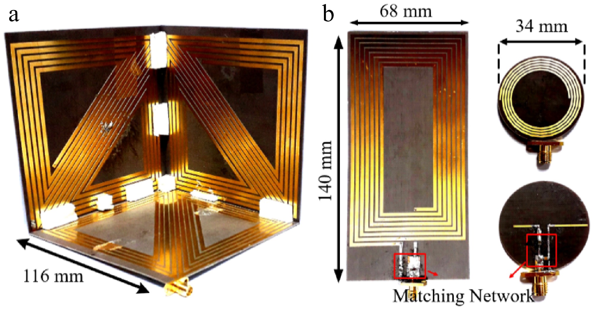
Figure 5.
(a) Fabricated HCS-Tx coil, (b) rectangular Rx coil, and (c) circular Rx coil.
Mutual inductance investigation
-
The mutual inductance is investigated for the HCS-Tx and rectangular Rx coil. The investigated results, as shown in Fig. 6 are implemented for two cases. In the first case, the rectangular Rx is in line with the Oxz plane and moved along the Oy axis. Similarly, the second case is verified when the Rx coil is positioned orthogonal to the Oyz plane and moved along the Ox axis. The moving distances on the Ox and Oy axis of the Rx coil are indicated by px and py, respectively. The calculation results are solved by using the mutual inductance Eq (9). The simulation results are extracted from the ANSYS Electronics Desktop software, whereas the experimental results are acquired using the Protek A333 Vector Network Analyzer (VNA).
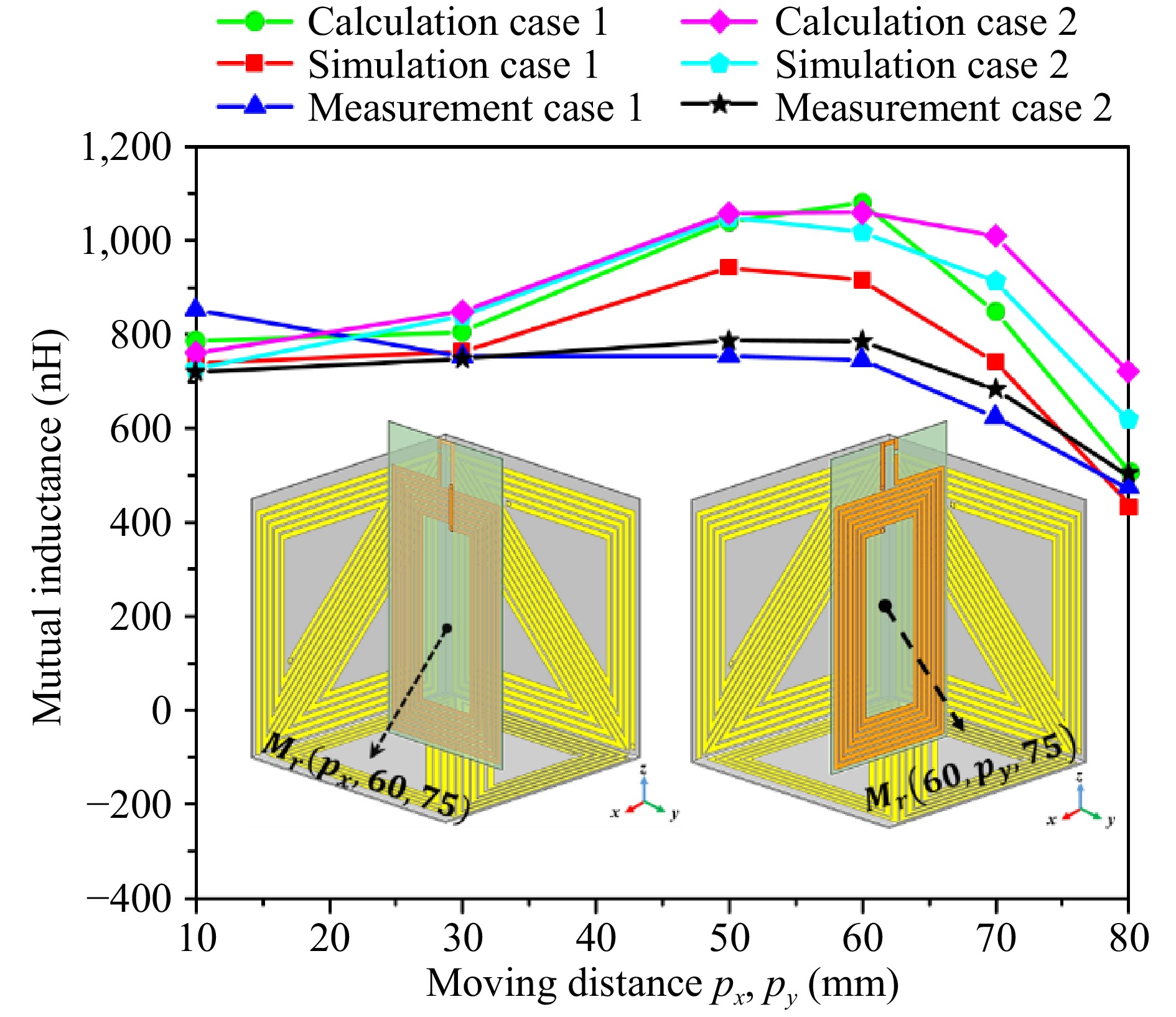
Figure 6.
Mutual inductance between the HCS-Tx coil and rectangular Rx coil.
From the investigation results shown in Fig. 6, it is obvious that the mutual inductance presents stability with px and py varied from 10 to 80 mm on both of verification cases. This region corresponds to the active charging volume of the Tx coil due to the significant strong magnetic field distribution. The mutual inductance is highest when the Rx is placed at the center area around px and py of 50 mm with the values almost achieved higher than 800 nH. Moreover, as the Rx coil shifts farther from the central region, the mutual inductance drops significantly due to the increased separation between the Rx coil and the three Tx sub-coils. The results obtained through calculations, simulations, and measurements shows strong correlation. However, the measured values are slightly lower, which can be attributed to fabrication tolerances.
Single receiver WPT system
-
The coil-to-coil power transfer efficiency (PTE) is evaluated to demonstrate the free-positioning capability of the HCS-Tx structure using various placements of the rectangular Rx coil. These Rx positions are illustrated in the schematic diagram in Fig. 3. The movement of the rectangular Rx coil is defined by the displacement vector
$ {\vec{\mathrm{S}}}_{\mathrm{r}} $ 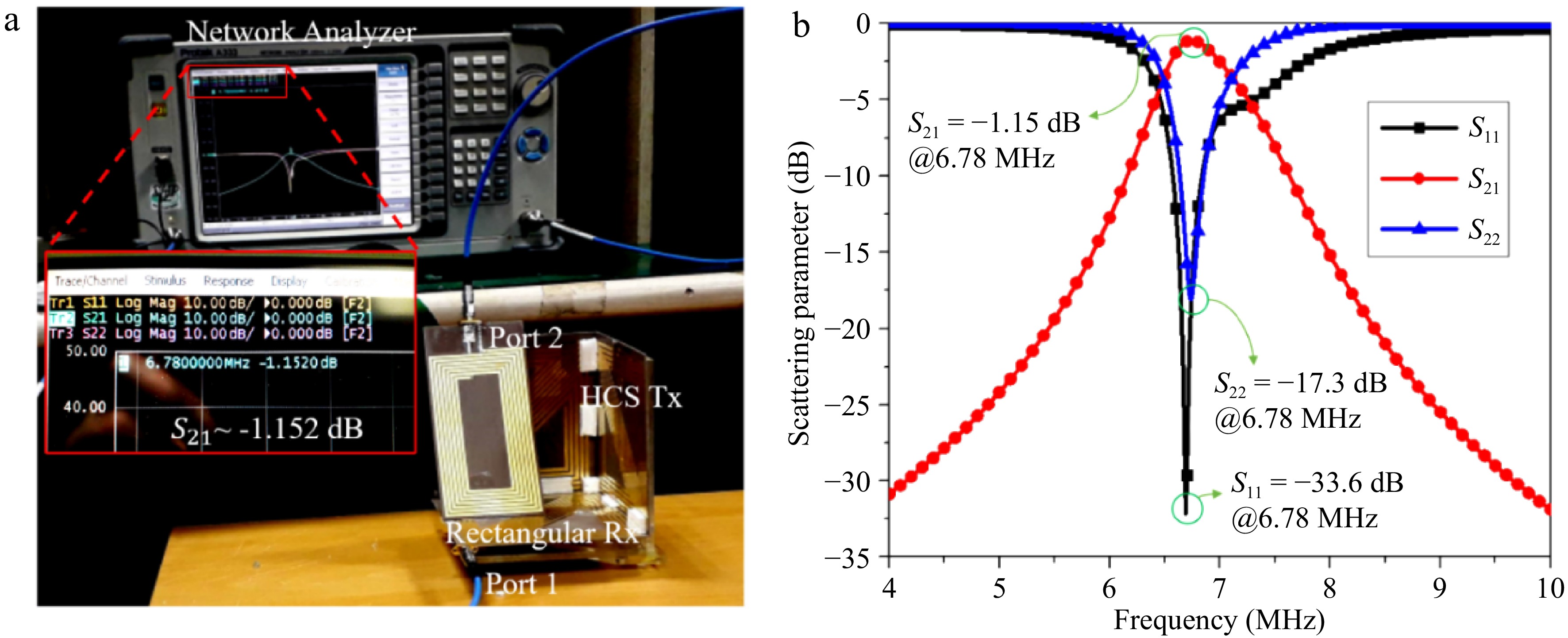
Figure 7.
(a) Single receiver WPT system measurement. (b) S-parameter results.
The highest coil-to-coil PTE achieved in the experiment with the rectangular Rx coil is demonstrated in Fig. 7b, which corresponds to the movement vector and rotation angles of the Rx coil are dxr = 82 mm, dyr = 26 mm, dzr = 60 mm, and φxr = 65°,φyr = 0°, φzr = 0°, respectively. It is important to note that the reflection coefficients of both the Tx and Rx coils are minimal, owing to the effective impedance matching network designed for the operating frequency of 6.78 MHz. From Fig. 7b, the maximum transmission coefficient S21 achieves −1.15 dB at 6.78 MHz corresponding to the PTE of 76.74%. To validate the free-positioning WPT efficiency, the Rx coil is moved freely inside HCS-Tx structure. The coil-to-coil PTE is verified with the angular misalignment by varying the angles φxr, φyr, and φzr, respectively. Meanwhile, the axial misalignment is also considered by increasing the distance between rectangular Rx and the opposite HCS-Tx plane. To further ensure the robustness of the system, measurements were conducted under various misalignment scenarios, simulating real-world conditions where perfect alignment is rarely guaranteed. The system maintained consistent PTE across a broad range of orientations and distances, demonstrating the effectiveness of the HCS-Tx design. These results affirm the suitability of the proposed setup for practical, flexible charging environments. Figure 8 illustrates the coil-to-coil transmission efficiency as a function of the Rx coil's angular and axial misalignments.
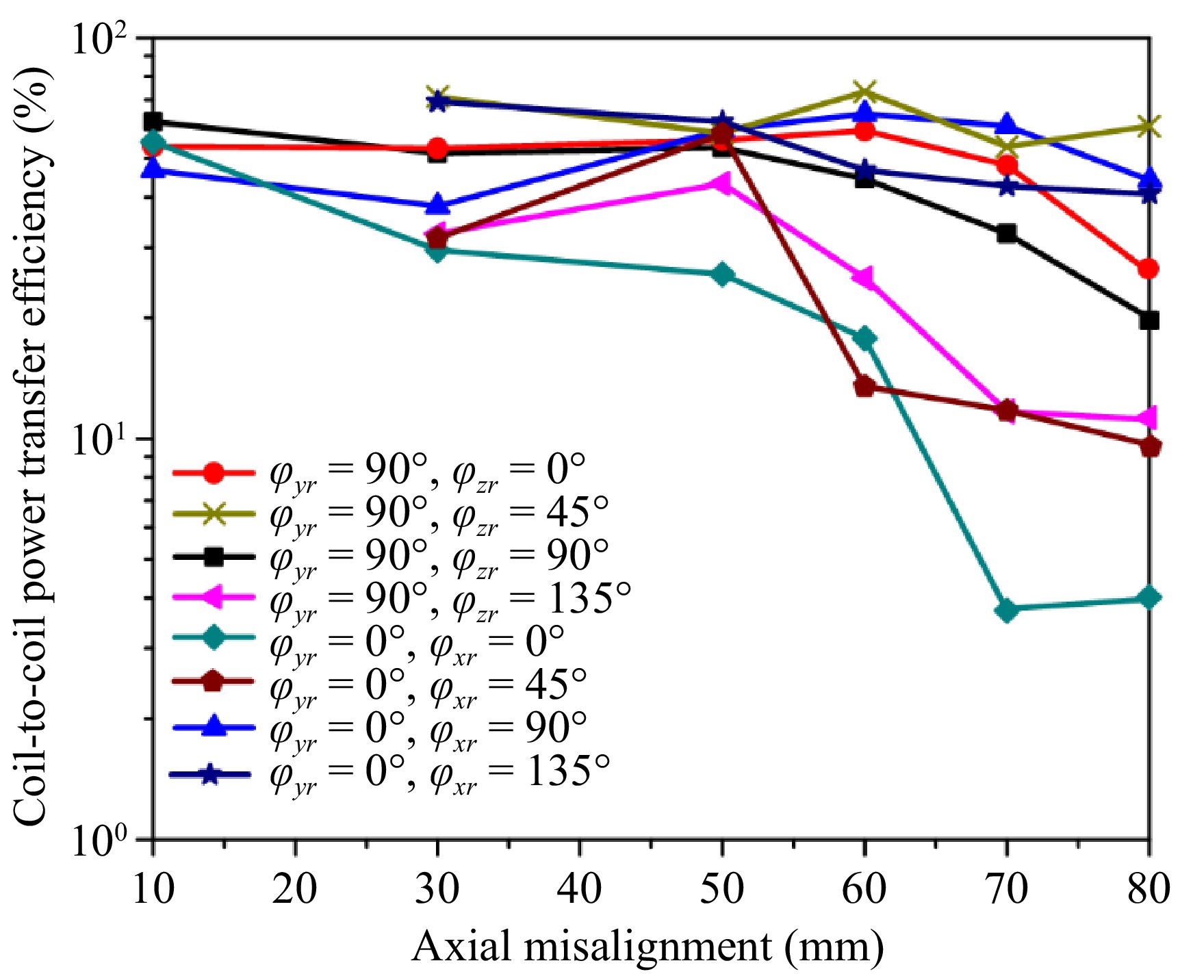
Figure 8.
Coil-to-coil power transfer efficiency.
The PTEs of rectangular Rx achieve a value of higher than 20% at almost all Rx arrangement scenarios, which shows the acceptable performance for a free-positioning WPT system. On the range of arrangement distance from 10 to 30 mm, the PTEs show an insignificant change as the Rx coil is rotated around its axis. Specifically, when the rotation angles φzr and φxr are varied with the step of 90°, the Rx coil is powered nearly uniformly because of the symmetrical Tx structure. In other words, by rotating Rx 45° around its axis, the PTEs present notable gaps because of the change in the direction of magnetic flux density. The Rx coil receives power the most effectively in the range from 10 to 60 mm, which corresponds to the strong magnetic field region. However, on the axial misalignment range from 60 to 80 mm, the PTEs present significant fluctuations at the axial misalignment positions because of the reduction in magnetic field intensity.
Multiple-receiver WPT system
-
To verify the performance of the free-positioning WPT system for multiple devices, the rectangular and circular Rx coils are placed inside the HCS-Tx coil simultaneously. The experiment is performed with some scenario arrangements of two Rx coils. The S-parameters of each Rx coil are measured alternately while another Rx coil is connected to the load of 50
$ \mathrm{\Omega } $ It is worth noting that the circular Rx achieves the more stable power transfer efficiency due to its smaller size compared with rectangular Rx. Specifically, the individual PTE of circular Rx remains at more than 20% for all of the verification scenarios, while the individual PTE of rectangular Rx has a significant gap between the highest and the lowest PTE approximating 15%.
Multiple-receivers wireless charging system
-
The performance of a free-positioning wireless charging system is validated with an arbitrary arrangement of the multiple-receivers system. The Rx circuit consists of an Rx coil, rectifier circuit, and a red LED to indicate charging status, as shown in Fig. 9a. A voltage doubler rectifier is used to convert the received RF power to an output DC voltage with high efficiency and output voltage. The use of two HSMS 2800 Schottky's diodes can enhance the input power range due to the breakdown voltage increase. The threshold voltage of the diode is V. The overall system efficiency is given by:
$ {{\eta }}_{\mathrm{s}\mathrm{y}\mathrm{s}}=\dfrac{{\mathrm{V}}_{\mathrm{D}\mathrm{C}1}^{2}+{\mathrm{V}}_{\mathrm{D}\mathrm{C}2}^{2}}{{\mathrm{R}}_{\mathrm{L}\mathrm{o}\mathrm{a}\mathrm{d}}\times{\mathrm{P}}_{\mathrm{R}{\mathrm{F}}_{\mathrm{i}\mathrm{n}}}}\times 100{\text{%}} $ (18) where,
$ {\mathrm{P}}_{\mathrm{R}{\mathrm{F}}_{\mathrm{i}\mathrm{n}}} $ 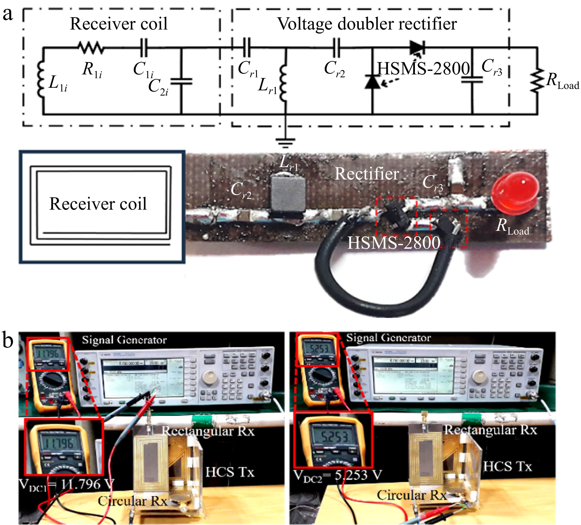
Figure 9.
(a) Schematic diagram of Rx circuit: Cr1 = 150 pF, Lr1 = 3.3 μH, Cr2 = 130 pF, Cr3 = 1 F, RLoad = 1.3 kΩ. (b) Experimental setup for the multiple-receivers wireless charging system with the positions of Rx coil represented by dxr = 82 mm, dyr = 14 mm, dzr = 65 mm, φxr = φyr = φzr = 0°, dxc = 80 mm, dyc = 40 mm, dzc = 5 mm, φxc = φyc = φzc = 0°.
The experimental validation of the proposed system is conducted by measuring the output voltage across each receiver (Rx) circuit under practical conditions. The half-cube-shaped transmitting coil (HCS-Tx) is powered by a signal generator (Agilent E4438C), delivering an input power level of 23 dBm. As a result of the wireless energy transfer, the output of the rectifying circuits connected to the rectangular and circular Rx coils achieves direct current (DC) voltages of approximately 11.8 and 5.2 V, respectively, as illustrated in Fig. 9b. These voltage levels reflect the capability of the system to maintain effective power delivery to multiple receivers, even when they differ in shape and position. By applying Eq. (18), which takes into account the input power and output DC levels, the overall wireless charging system demonstrates an efficiency of approximately 64%.
To further illustrate the effectiveness of the proposed approach, Table 2 presents a performance comparison between this work and several recent studies in the field. The comparison includes critical parameters such as the wireless power transfer method, resonant operating frequency, physical dimensions of the transmitter coil, and the maximum achieved power transfer efficiency (PTE).
Table 2. Summary of measured power transfer efficiency of multiple-receivers WPT system.
Rectangular Rx Circular Rx Overall PTE Coordinate (mm) Angle (°) PTE Coordinate (mm) Angle (°) PTE dxr dyr dzr φxr φyr φzr dxc dyc dzr φxc φyc φzc 82 26 60 65 0 0 74.13% 35 85 5 0 0 0 20.42% 94.55% 82 26 60 65 0 0 73.79% 5 35 35 0 90 0 22.35% 96.14% 82 26 60 65 0 0 74.64% 5 80 80 0 90 0 20.42% 95.06% 82 14 65 70 0 0 65.77% 80 40 5 0 0 0 20.42% 86.19% 82 14 65 70 0 0 70.79% 80 40 5 0 0 0 22.38% 93.18% This analysis highlights the advantages of the HCS-Tx design in delivering high PTE and robust free-positioning capabilities, making it a strong candidate for real-world applications involving multiple, spatially flexible receivers.
The experiment results are obtained by measuring the output voltage on each Rx circuit. The HCS-Tx is supplied power of 23 dBm using the signal generator Agilent E4438C. The output rectified voltage of the rectangular and circular Rx circuit is approximately 11.8 and 5.2 VDC, respectively, as shown in Fig. 9b. By applying Eq. (18), the overall system efficiency is approximately 64%.
Table 3 presents an extensive comparison of wireless power transfer (WPT) systems operating at 6.78 MHz with multiple receivers, emphasizing power transfer efficiency. The data indicate that our proposed free-positioning WPT system, featuring the HCS-Tx structure, achieves an outstanding multi-receiver efficiency of 96.14%, surpassing all referenced works in this respect. Nevertheless, while this result is promising, further enhancements in overall system efficiency is needed to optimize power transfer performance even more.
Table 3. Performance Comparison of wireless power transfer (WPT) systems operating at 6.78 MHz with multiple receivers.
WPT method Resonant
frequency (MHz)Coil-to-coil transmission efficiency System efficiency Ref. Single Rx Multiple Rx Planar Tx coil with switchable IMNs 6.78 82.1% 93% NG [11] Class E amplifier with multiple receivers 6.78 NG 71.7% NG [29] WPT system for multiple receivers operating at Inductive and Resonant Operating Modes 6.78 NG 83% 66% [30] WPT system for a dual-mode transmitter, along with two receivers 6.78 NG 78% NG [31] Printed spiral half-cube shaped Tx structure 6.78 76.74% 96.14% 64% This work Figure 10 visually illustrates the efficiency metrics of each WPT method, clearly showing the advantages of the half-cube-shaped transmitter (HCS-Tx) implemented in this study. Not only does the proposed system outperform existing designs in terms of multiple receiver efficiency, but it also demonstrates a competitive system-level efficiency of 64%. This graphical comparison underscores the robustness and effectiveness of the proposed free-positioning solution in practical multi-device charging scenarios.
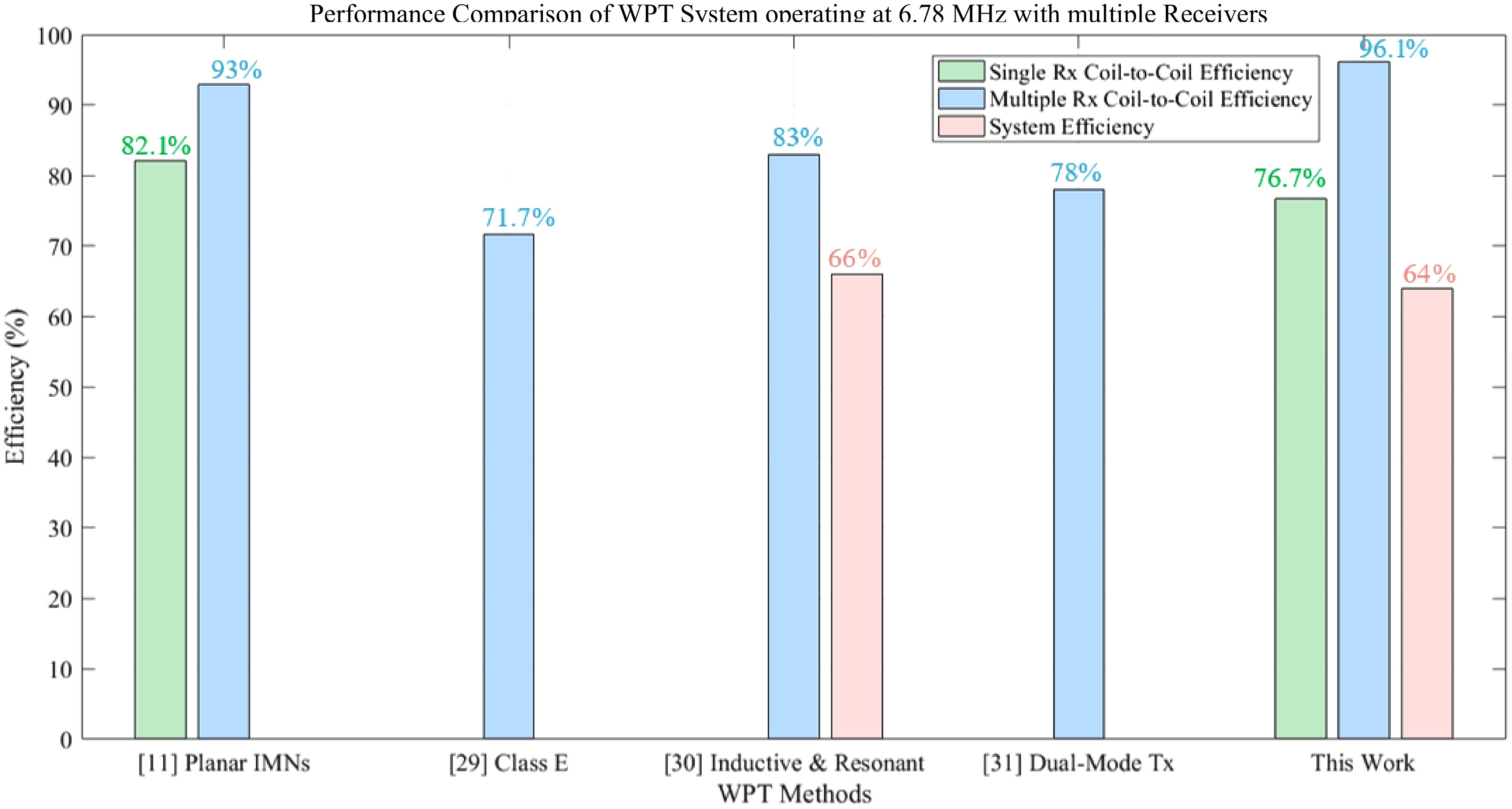
Figure 10.
Performance comparison of wireless power transfer (WPT) systems operating at 6.78 MHz with multiple receivers.
Figure 11 offers a detailed overview of the performance and operational behavior of a wireless power transfer (WPT) system designed for a transmitter and multiple receivers. The first graph demonstrates the dynamic nature of the transmitter, showcasing periodic fluctuations in input voltage and current, with voltage oscillating between −10 and 10 V, and current ranging from −200 to 200 mA. The second graph highlights the transmitter's input power, which peaks periodically at 2 W, representing the energy supplied to the system during operation. The third graph focuses on the load voltages of three receivers, Rx1, Rx2, and Rx3, exhibiting consistent oscillations between −2 and 2 V, which indicates uniform load conditions and functionality. The fourth graph captures the load currents of the receivers, which fluctuate within a range of −50 to 50 mA, demonstrating effective energy exchange between the transmitter and receivers. Additionally, the fifth graph illustrates the load power delivered to the receivers, reaching a peak of approximately 0.1 W, thereby showcasing efficient power distribution among the receivers in multi-receiver scenarios. Finally, the sixth graph compares the input and output power of the system, revealing that the input gradually increases up to 2 W, while the output power remains stable around 0.1 W, underscoring the system's efficiency and steady performance. Together, these graphs emphasize the robust design and operational success of the WPT system.
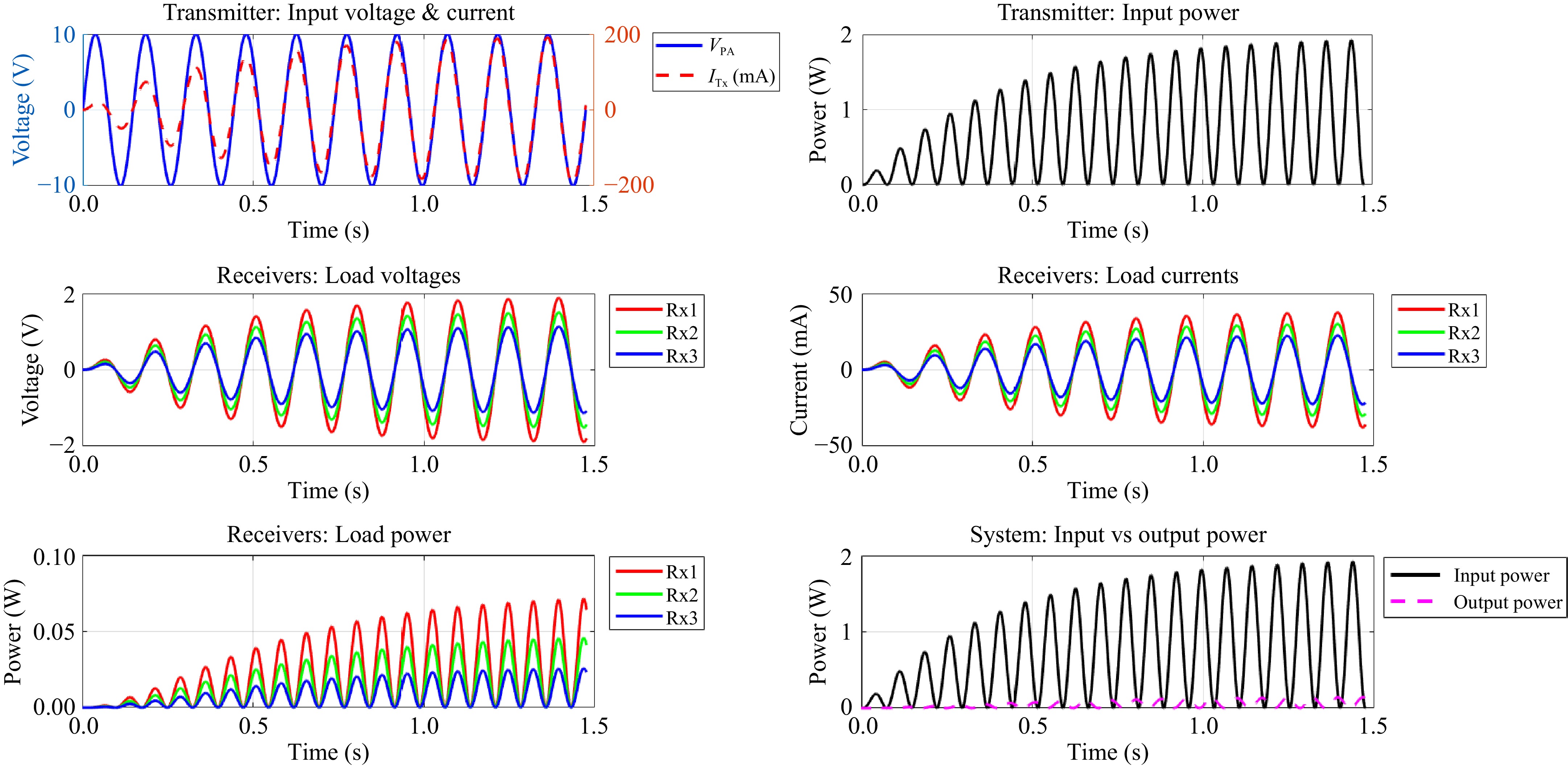
Figure 11.
Waveform diagram to illustrate the relationship between electrical parameters.
-
This study presents a free-positioning WPT system tailored for applications involving multiple receivers. A strong magnetic field distribution is achieved in freedom[3] spatial by controlling the current direction. The mutual inductance is derived for the HCS-Tx and a moving Rx to verify its stability. Additionally, the equivalent circuit of the multi-receiver WPT system is theoretically analyzed to formulate the power transfer efficiency (PTE) equation. The experimental findings validate that the proposed system efficiently transmits power to both single and multiple receivers. The proposed Tx coil can deliver power with an overall coil-to coil efficiency of 76.74% with a single receiver, and 96.14% with a multiple-receivers WPT system. These findings emphasize the capability of the proposed system to enhance power transfer performance and optimize energy distribution across multiple receivers. In addition, a wireless charging system was implemented to achieve 64% of the overall system efficiency. In conclusion, the WPT system using an HCS Tx coil presents a practical feasibility of a free-positioning wireless power transfer, catering to both single and multiple receivers with enhanced stability and performance.
To expand the scope of this research and enhance the practical applicability of the proposed wireless power transfer (WPT) system, several potential directions can be explored in future studies. One promising area is the investigation of system performance under varying power demands from multiple receivers, which would support stable and efficient operation in dynamic load conditions. Additionally, scaling the system to accommodate a larger number of receivers without degrading efficiency or increasing undesired cross-coupling remains an important challenge. This could be addressed through optimized coil designs or the development of advanced control and coordination strategies.
Future work could also focus on mitigating environmental factors such as temperature variations and electromagnetic interference while addressing practical concerns including hardware miniaturization and cost reduction. These efforts would contribute significantly to bridging the gap between experimental prototypes and real-world deployment, thereby advancing the realization of free-positioning WPT systems for diverse applications.
This research was partially funded by the National Natural Science Foundation of China (Grant No. 52277004), the QingLan Project of Jiangsu Province, and the Jiangsu Provincial Key Laboratory of Smart Grid Technology and Equipment at Southeast University.
-
The authors confirm contribution to the paper as follows: study conception and design: Naveed I, Tan L; data collection: Naveed I, Hussain A; analysis and interpretation of results, draft manuscript preparation: Naveed I, Yameen MZ, Hussain A; funding acquisition and supervision: Tan L. All authors reviewed the results and approved the final version of the manuscript.
-
All data generated or analyzed during this study are included in this published article.
-
The authors declare that they have no conflict of interest.
- Copyright: © 2025 by the author(s). Published by Maximum Academic Press, Fayetteville, GA. This article is an open access article distributed under Creative Commons Attribution License (CC BY 4.0), visit https://creativecommons.org/licenses/by/4.0/.
-
About this article
Cite this article
Naveed I, Tan L, Yameen M, Hussain A. 2025. Free-positioning wireless power transfer for multiple-receivers using a half-cube shaped transmitting coil. Wireless Power Transfer 12: e021 doi: 10.48130/wpt-0025-0016 

Free-positioning wireless power transfer for multiple-receivers using a half-cube shaped transmitting coil
- Received: 05 March 2025
- Revised: 22 April 2025
- Accepted: 14 May 2025
- Published online: 20 August 2025
Abstract: In recent developments, free-positioning wireless power transfer (WPT) systems have become a practical solution for simultaneously powering multiple devices. This paper proposes a half-cube-shaped transmitting coil for free-positioning multiple-receiver WPT systems. The receiving devices are placed inside the transmitter and charged effectively in spatial freedom. A rectangular coil and a smaller circular coil are utilized as receiving coils to investigate the performance of the WPT system in a typical application scenario. Practical experiments are implemented to evaluate the PTE depending on the receiver's movement. The results provide valuable insights into optimizing the design for spatially dynamic charging applications. Furthermore, the system's scalability suggests its potential utility in diverse multi-device charging scenarios. The measurement results demonstrate that the WPT system is capable of delivering 76.74% PTE for a single receiver, and 96.14% overall PTE to multiple receivers. Finally, a multiple-receiver wireless charging system using an RF-DC rectifier is designed to determine system efficiency, which demonstrates approximately 64% overall efficiency for charging multiple receivers simultaneously.