-
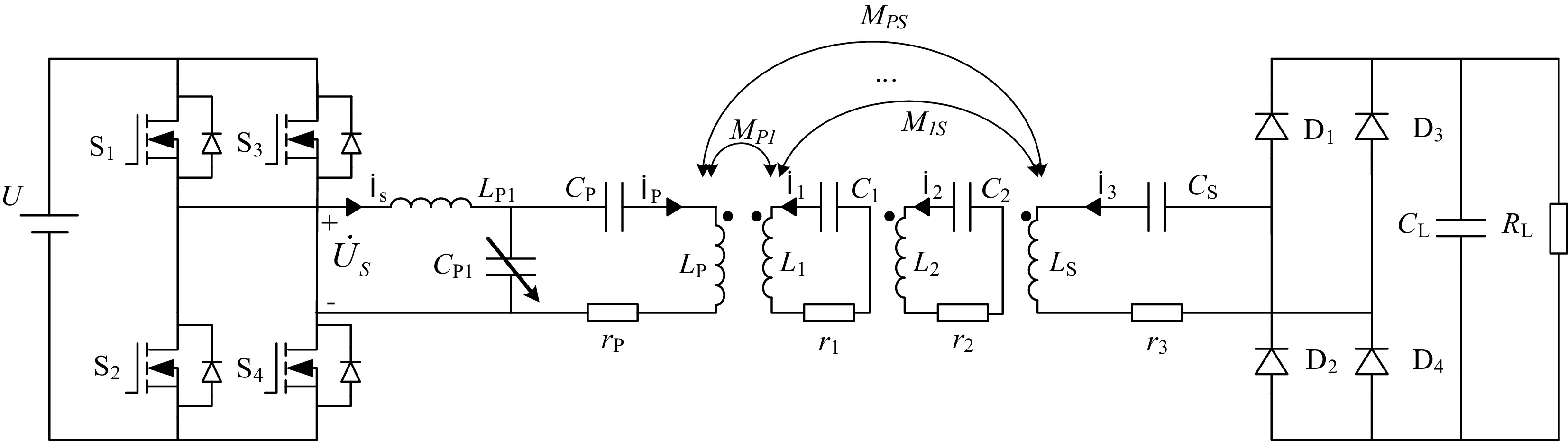
Figure 1.
Circuit topology of LCC-S multi-relay WPT system.
-
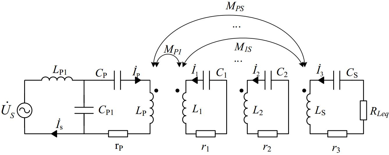
Figure 2.
Equivalent circuit diagram of LCC-S type multi-relay WPT system.
-
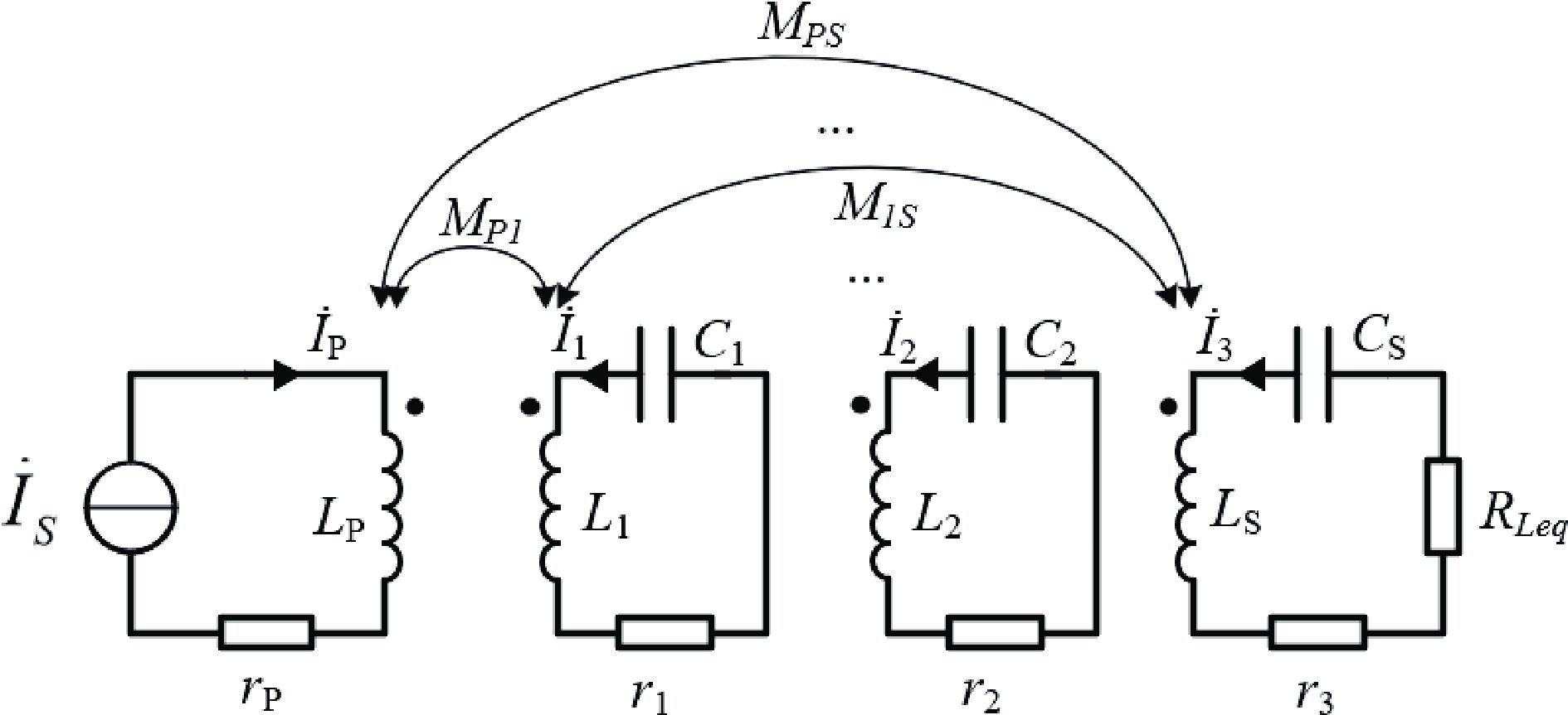
Figure 3.
Simplified equivalent circuit diagram of LCC-S type multi-relay WPT system.
-
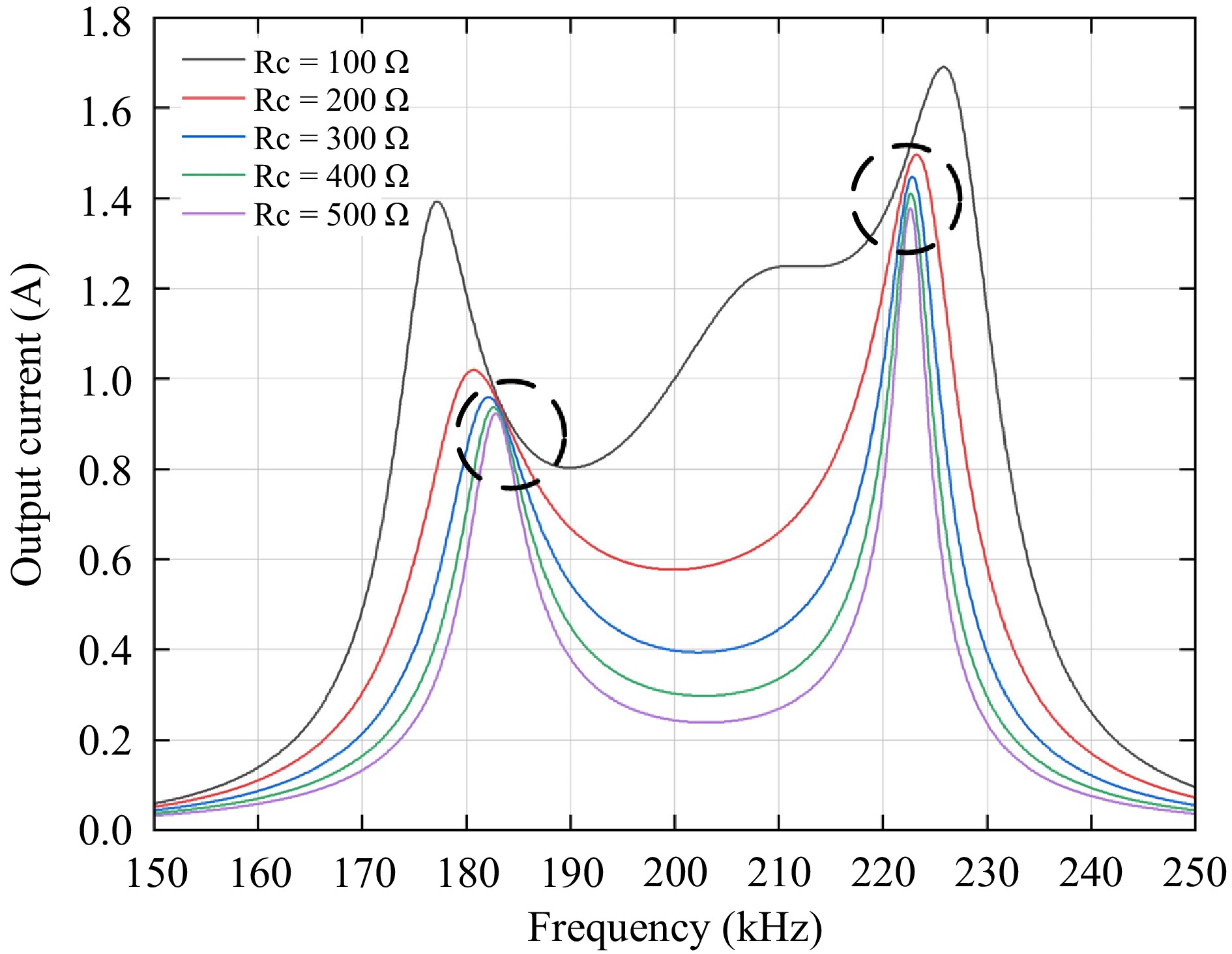
Figure 4.
Four-Coil WPT system output current versus frequency curve.
-
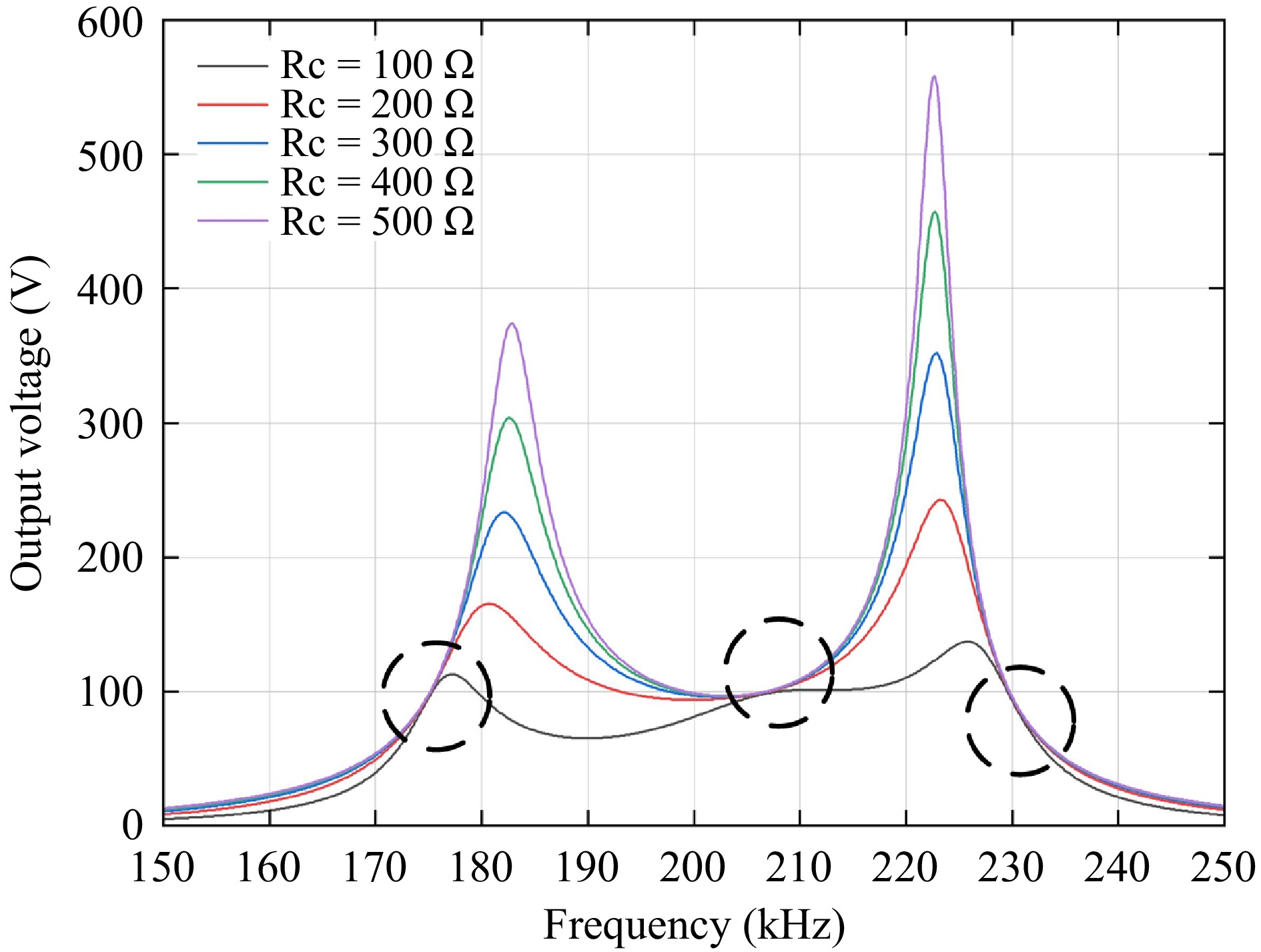
Figure 5.
Four-coil WPT system output voltage versus frequency curve.
-
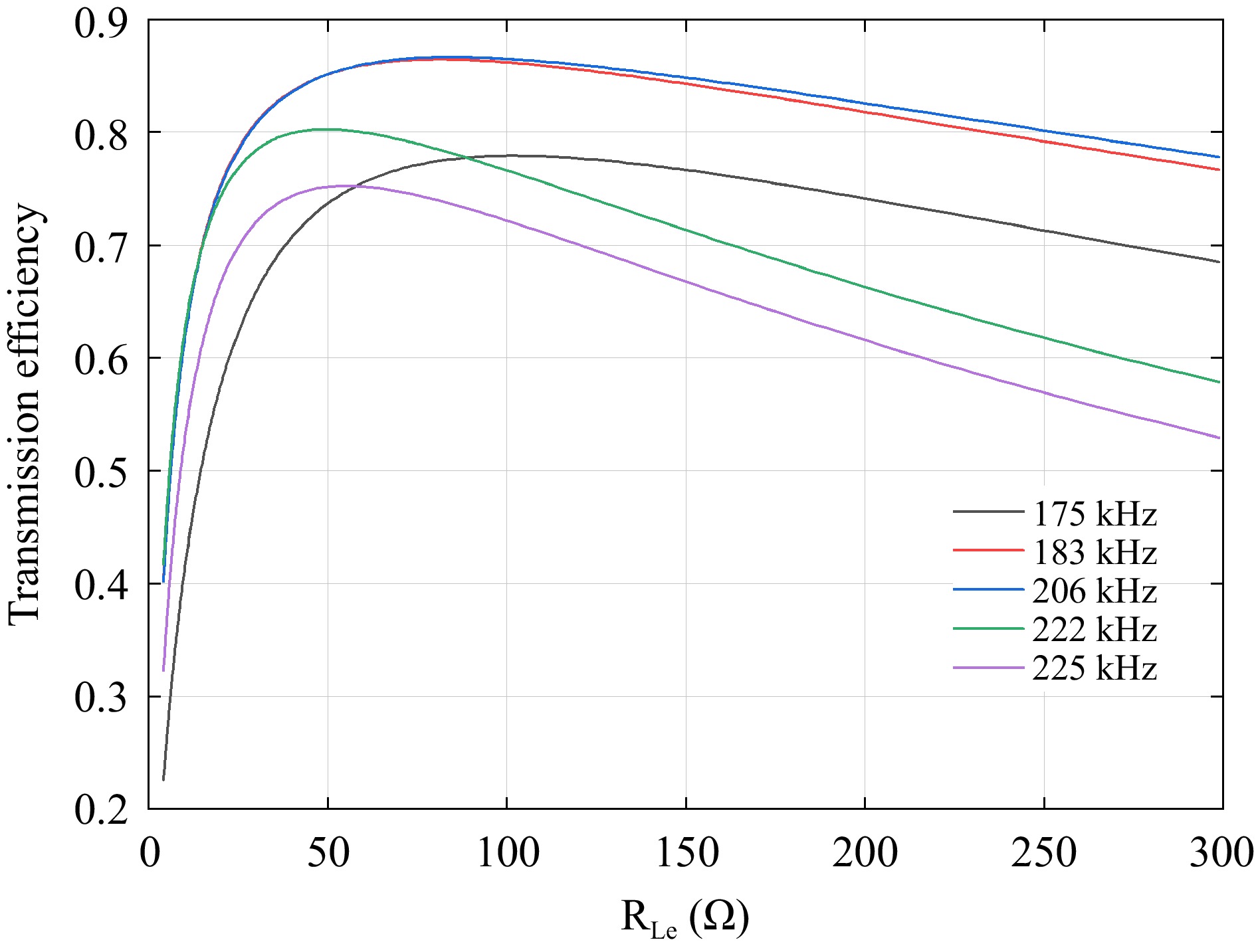
Figure 6.
System transmission efficiency at five critical frequencies.
-
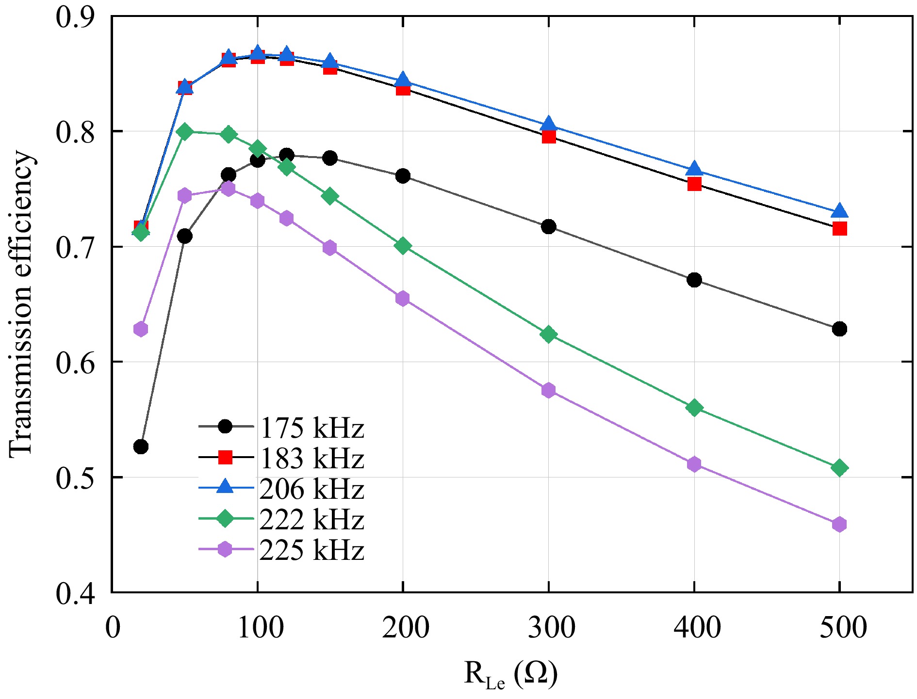
Figure 7.
Dot plot of efficiency at five key frequencies.
-
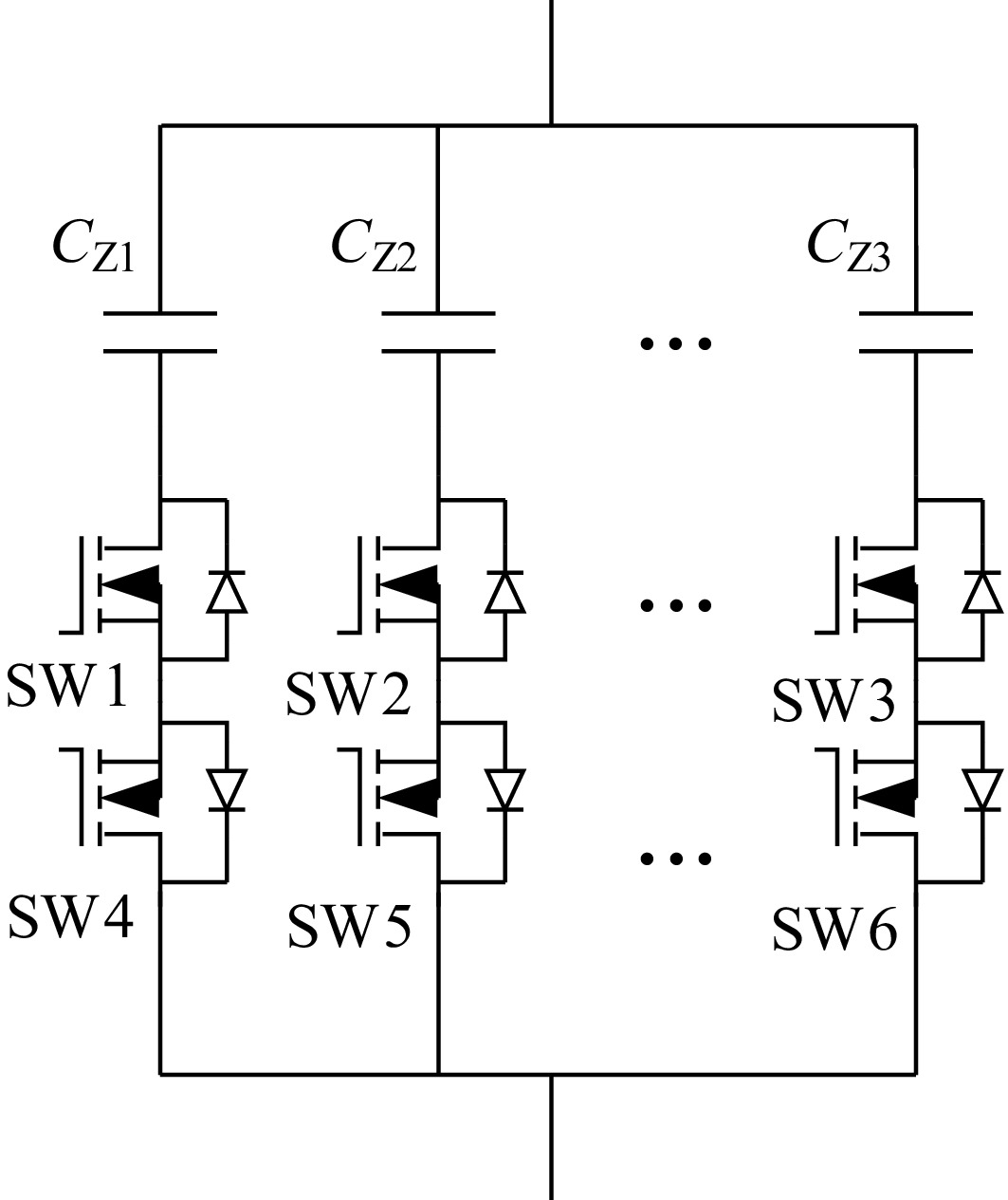
Figure 8.
Schematic diagram of switched capacitor matrix.
-
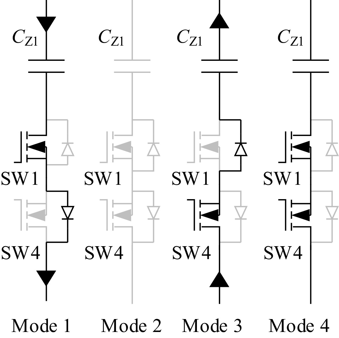
Figure 9.
Four operation modes of switched capacitor matrix.
-
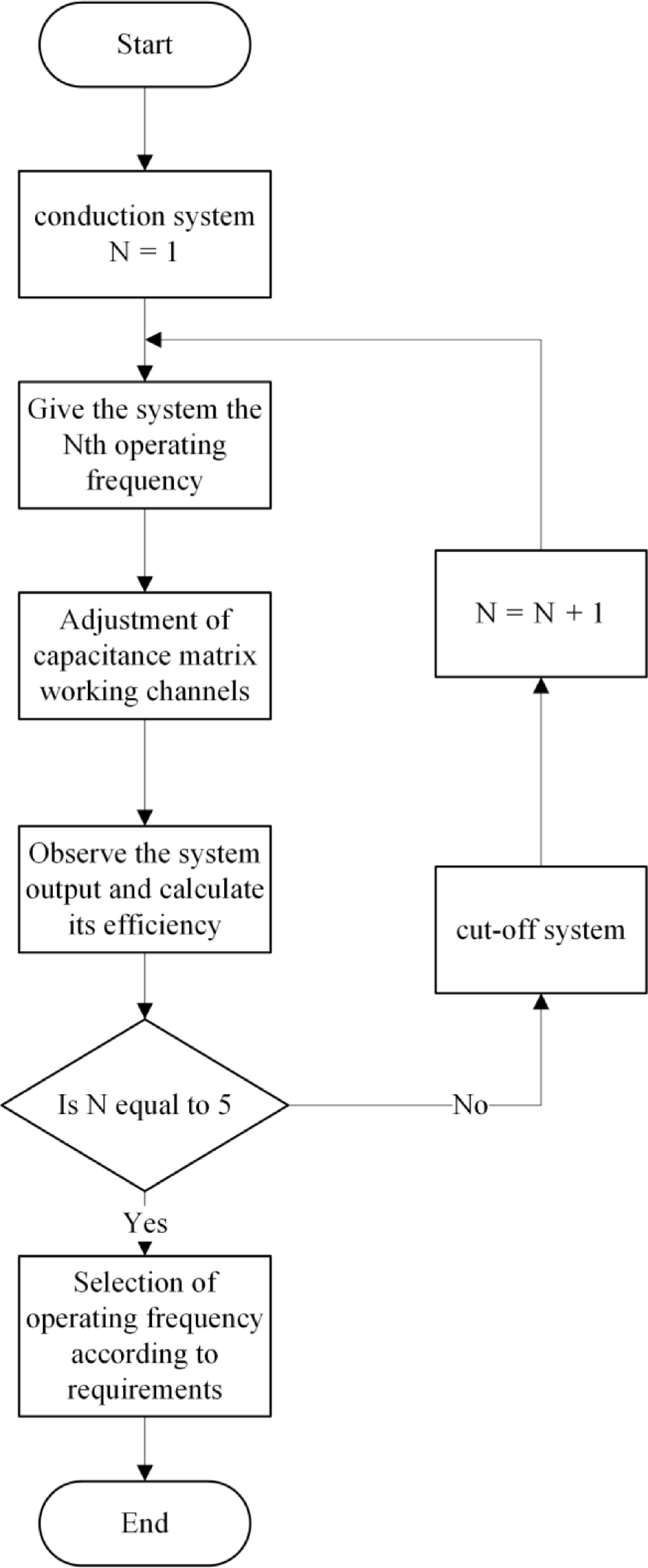
Figure 10.
System control block diagram.
-
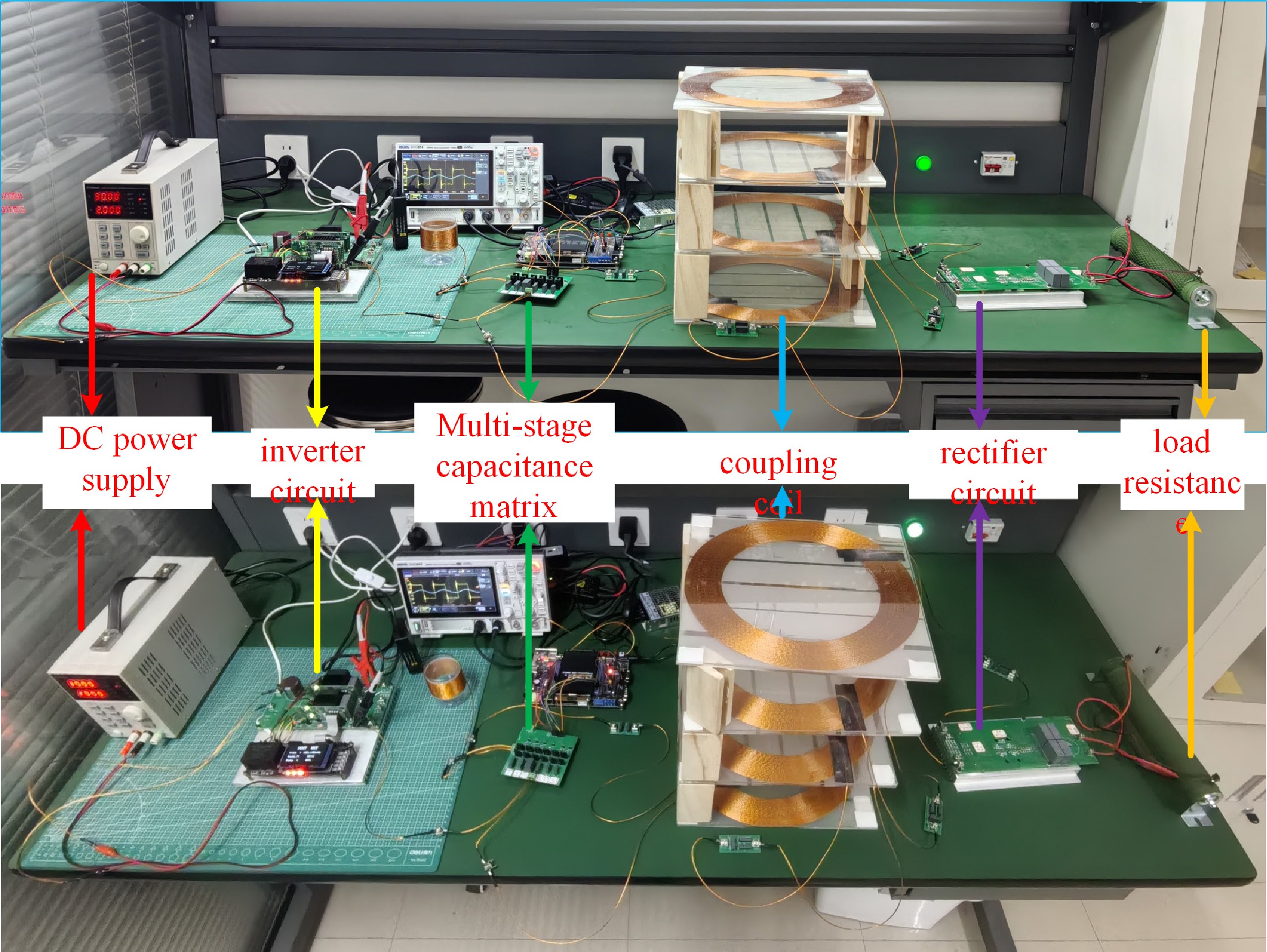
Figure 11.
LCC-S type multi-relay WPT system experimental device.
-
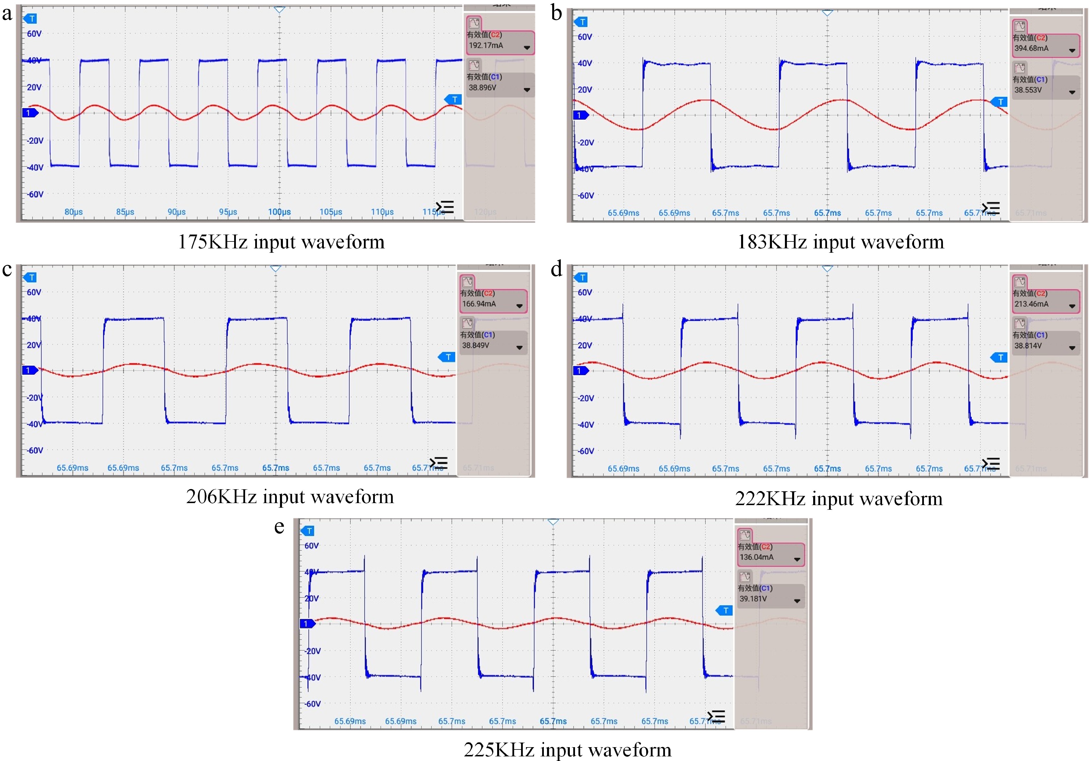
Figure 12.
Input waveform of experimental equipment.
-
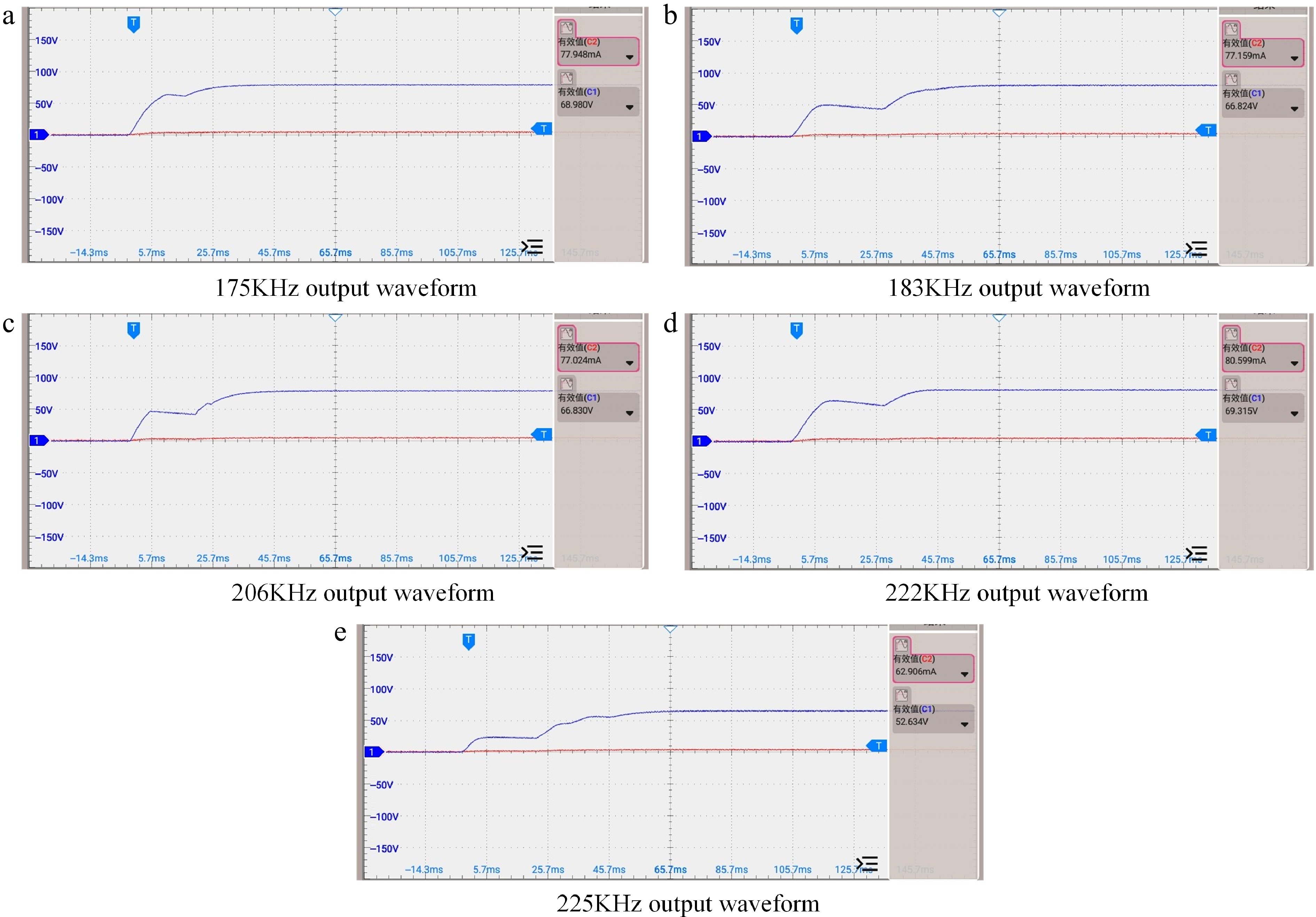
Figure 13.
Output waveform of experimental equipment.
-
Current frequency Operating frequency (KHz) Voltage frequency Operating frequency(KHz) CC1 183 CV1 175 CC2 222 CV2 206 CV3 225 Table 1.
Four-Coil WPT system constant current and constant voltage frequency.
-
Capacitance number Capacitance value (nF) CZ1 12 CZ2 12 CZ3 6.8 CZ4 27 CZ5 22 CZ6 2.7 Table 2.
Values of the fixed capacitances in the capacitance matrix.
-
Frequency (KHz) Selection of capacitance matrix 175 CZ4 183 CZ1, CZ2 206 CZ5 222 CZ1, CZ3 225 CZ1, CZ6 Table 3.
Values of resonant capacitance at different key frequencies.
-
Parameters Values U (V) 100 LP (μH) 30 LP1, L1, L2, LS (μH) 365 MP1, M12, M2S (μH) 68 MP2, M1S (μH) 22 MPS (μH) 10 CP (nF) 1.9 C1, C2, CS (nF) 1.73 CL (μF) 2 Table 4.
Element parameters of four-coil multi-relay compensation network.
-
Frequency (KHz) Equivalent load (Ω) Transmission efficiency 175 100 71.94% 183 100 42.07% 206 100 79.37% 222 100 71.94% 225 100 62.11% Table 5.
Experimental transmission power and efficiency of four-coil WPT system at different input frequencies.
Figures
(13)
Tables
(5)