


-
With technological advancements, traditional power transmission faces security challenges and inherent limitations. Wireless power transfer (WPT), known for its safety, reliability, and low maintenance, is increasingly used in electric vehicles[1], biomedicine[2], and other specialized applications.
Due to environmental and climatic factors[3,4], wired power supply faces significant limitations in online monitoring equipment for high voltage transmission line[5]. As a result, WPT is increasingly adopted as an alternative power solution. Furthermore, since conventional two-coil systems can no longer meet the demands for long-distance transmission, researchers have begun to explore and utilize multi-relay WPT systems.
However, in the process of wireless power transfer, various methods have been explored to improve transmission efficiency, with optimizing the compensation network being the preferred solution. For multi-relay WPT systems, the frequency-splitting phenomenon results in multiple resonant frequencies, rendering fixed compensation networks inadequate to address frequency splitting and its negative effects[6,7]. To solve this problem, a switch-controlled capacitor (SCC)[8] has been employed to dynamically reconfigure the compensation network, enabling real-time switching of resonant frequencies to enhance system performance, such as transmission power and efficiency.
A hybrid control strategy integrating phase shift modulation (PSM) with a switch-controlled capacitor (SCC) is proposed[9]. An additional SCC component is integrated into the LCC-S compensation network, and its operation is regulated through feedback. This approach reduces the losses in the primary coil under light-load conditions and enhances the system's transmission efficiency. A reactance elimination method based on an impedance buffer is proposed[10]. This method achieves full-range zero-phase angle (ZPA) operation by connecting a synchronous impedance buffer in series with the CLC compensation network, thereby eliminating reactance. A method incorporating a controllable switched capacitor (SCC) into the compensation network is proposed[11], adjusting the total output power and input impedance by regulating the inverter's duty cycle and transmitter-side compensation capacitance. The studies show that optimizing the compensation network improves transmission efficiency and enables constant current (CC) and constant voltage (CV) output. A zero-voltage switching (ZVS) controller design method for WPT systems is proposed[12], using a feedback controller and a five-stage variable capacitor. This ensures the ZVS angle remains at the reference angle during load changes, achieving reliable control. However, the SCC approach necessitates intricate parameter identification as a prerequisite and depends on communication support, resulting in higher costs, greater system complexity, and reduced robustness. Moreover, its continuous adjustability introduces substantial energy losses. The method of synchronizing the buffer and inverter sections increases system complexity and cost due to the required coordination between two sets of drive frequencies.
The study analyzes the transmission characteristics of a four-relay multi-coil wireless power transfer (MC-WPT) system in series-series (S-S) and series-parallel (S-P) topologies and proposes a global tracking method to achieve optimal transmission efficiency under variable load conditions by switching between S-S and S-P topologies[13]. This study proposes an improved design method for both the coupling mechanism and compensation capacitors in multi-relay WPT systems based on segmented compensation. This approach effectively addresses the issue of sudden voltage spikes occurring in partial coils and at resonant capacitor terminals when the system operates at constant-voltage frequency[14]. Multi-relay coil WPT systems can significantly extend transmission distance and improve operational flexibility, but they also introduce notable technical challenges. These systems are prone to frequency-splitting phenomena, resulting in multiple resonant peaks that lead to unstable power transfer efficiency. A key unresolved issue is how to rapidly switch compensation capacitors to enable the system to achieve maximum transmission efficiency quickly.
To address these challenges, a multi-stage switched capacitor matrix method is proposed. This switched capacitor matrix, functioning as a configurable compensation capacitor, is particularly suitable for high-frequency applications. It employs relay-controlled discrete signals to switch different branches, thereby reducing losses caused by continuous signal operation. First, a mathematical model of the four-coil multi-relay LCC-S compensation network WPT system is developed, analyzing its transmission efficiency as well as constant current (CC) and constant voltage (CV) characteristics. Next, transmission efficiency curves are derived for different loads and resonant frequencies. The resonant capacitance of the transmitter is then adjusted to achieve CC or CV output under varying input frequencies and loads, ensuring high efficiency. Finally, an experimental platform is built to verify the effectiveness of the proposed method.
-
Figure 1 illustrates the circuit topology of the LCC-S type multi-relay WPT system. Here, U is the DC input power supply,
${\dot U_{\text{s}}}$ $\in $ 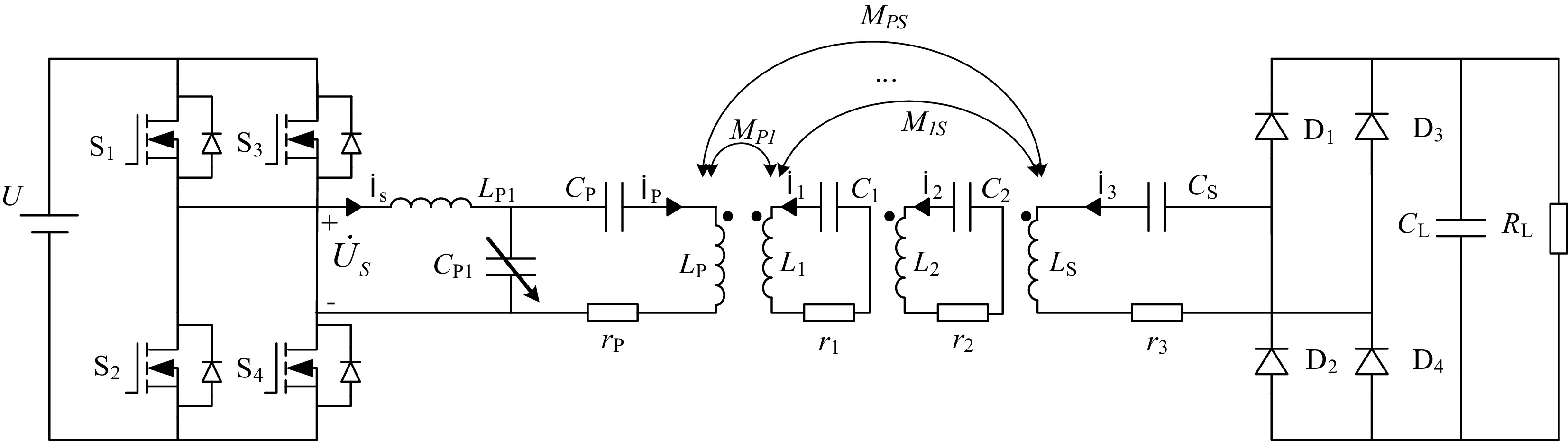
Figure 1.
Circuit topology of LCC-S multi-relay WPT system.
The equivalent circuit diagram of the LCC-S compensation network multi-relay MC-WPT system is shown below. The transmitter-side compensation network consists of LP1, CP1, and CP, while the receiver-side compensation network includes only CS. İS and İ3 represent the input and output currents, respectively. The DC voltage source U and the inverter in Fig. 2 are collectively equivalent to the AC voltage source
${\dot U_{\text{s}}}$ 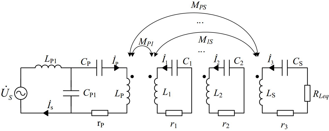
Figure 2.
Equivalent circuit diagram of LCC-S type multi-relay WPT system.
ω0 represents the resonant frequency of the system circuit. relay, and receiver are ω1, ω2, and ω3, respectively. The relationship between these resonant frequencies and the compensation network parameters is as follows:
$ \left\{\begin{gathered}{\omega }_{1}=\dfrac{1}{\sqrt{({L}_{P}-{L}_{P1}){C}_{P}}}\\ {\omega }_{2}=\dfrac{1}{\sqrt{{L}_{1}{C}_{1}}}=\dfrac{1}{\sqrt{{L}_{2}{C}_{2}}}\\ {\omega }_{3}=\dfrac{1}{\sqrt{{L}_{S}{C}_{S}}}\end{gathered}\right. $ (1) Based on the relationship between the compensation network and the resonant frequency, the system's equivalent circuit can be further simplified as shown in Fig. 3 when ω0 = ω1 = ω2 = ω3.
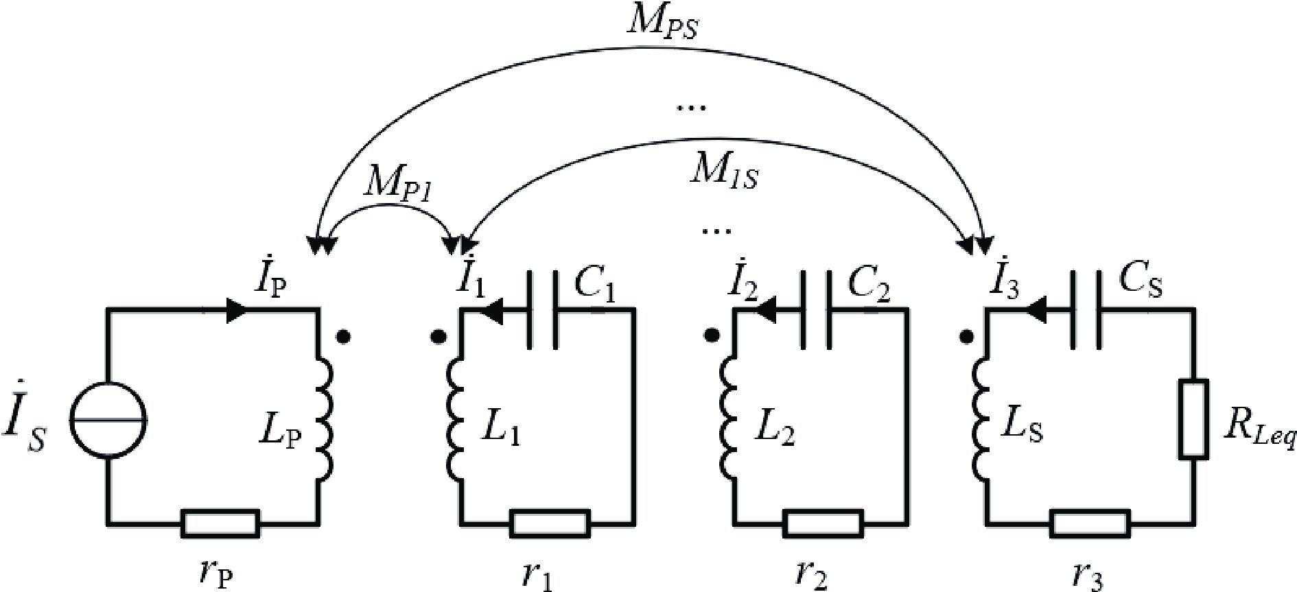
Figure 3.
Simplified equivalent circuit diagram of LCC-S type multi-relay WPT system.
Based on Figs 1 and 3, the system's quadratic characteristic equation is expressed as follows.
$ \left(j\omega\boldsymbol{L}+\boldsymbol{R}+\dfrac{\mathbf{C}}{j\omega}\right)\left[\begin{array}{l}\dot{I}_1 \\ \dot{I}_2 \\ \dot{I}_3\end{array}\right]=-j\omega\left[\begin{array}{*{20}{c}}M_{P1} \\ M_{P2} \\ M_{P3}\end{array}\right]_{ }\dot{I}_P $ (2) Here, the matrices L, R, and C are defined as follows:
$ {\boldsymbol{L}} = \left[ {\begin{array}{*{20}{c}} {{L_1}}&{{M_{12}}}&{{M_{1S}}} \\ {{M_{12}}}&{{L_2}}&{{M_{2S}}} \\ {{M_{1S}}}&{{M_{2S}}}&{{L_S}} \end{array}} \right] $ (3) $ {\boldsymbol{R}} = \left[ {\begin{array}{*{20}{c}} {{R_1}}&0&0 \\ 0&{{R_2}}&0 \\ 0&0&{{R_{L{\text{eq}}}}} \end{array}} \right] $ (4) $ {\boldsymbol{C}} = \left[ {\begin{array}{*{20}{c}} {{C_1}^{ - 1}}&0&0 \\ 0&{{C_2}^{ - 1}}&0 \\ 0&0&{{C_S}^{ - 1}} \end{array}} \right] $ (5) In the figure, RLeq is the equivalent load resistance of the rectifier output, which can be expressed as:
$ {R_{L{\text{eq}}}} = \dfrac{8}{{{\pi ^2}}}{R_L} $ (6) At system resonance,
$ \dfrac{1}{{j\omega {C_1}}} + j\omega {L_1} = \dfrac{1}{{j\omega {C_2}}} + j\omega {L_2} = \dfrac{1}{{j\omega {C_S}}} + j\omega {L_S} = 0 $ $\begin{gathered} \left[ {\begin{array}{*{20}{c}} {\dfrac{1}{{j\omega {C_{P1}}}} + j\omega {L_{P1}}}&{\dfrac{1}{{j\omega {C_P}}}}&0&0&0 \\ {\dfrac{1}{{j\omega {C_{P1}}}}}&{\dfrac{1}{{j\omega {C_{P1}}}} + \dfrac{1}{{j\omega {C_P}}} + j\omega {L_P}}&{j\omega {M_{12}}}&{j\omega {M_{13}}}&{j\omega {M_{14}}} \\ 0&{j\omega {M_{12}}}&0&{j\omega {M_{23}}}&{j\omega {M_{24}}} \\ 0&{j\omega {M_{13}}}&{j\omega {M_{23}}}&0&{j\omega {M_{34}}} \\ 0&{j\omega {M_{14}}}&{j\omega {M_{24}}}&{j\omega {M_{34}}}&{{R_L}} \end{array}} \right] \cdot \\ \left[ {\begin{array}{*{20}{c}} {{{\dot I}_S}} \\ {{{\dot I}_P}} \\ {{{\dot I}_1}} \\ {{{\dot I}_2}} \\ {{{\dot I}_3}} \end{array}} \right] = \left[ {\begin{array}{*{20}{c}} {{{\dot U}_S}} \\ 0 \\ 0 \\ 0 \\ 0 \end{array}} \right] \end{gathered}$ (7) From Eq. (7), the current in each branch/path of the system can be derived.
Additionally, by solving the KVL equation, the input and output active power, as well as the transmission efficiency of the system, can be determined. The specific formulas are as follows:
$ {P_{{\text{out}}}} = {I_3}^2{R_L} $ (8) $ {P}_{\text{in}}={I}_{P}{}^{2}{r}_{P}+{I}_{1}{}^{2}{r}_{1}+{I}_{2}{}^{2}{r}_{2}+{I}_{3}{}^{2}({R}_{3}+{R}_{L}) $ (9) $ \eta = \dfrac{{{P_{{\text{in}}}}}}{{{P_{{\text{out}}}}}} = \dfrac{{{R_L}}}{{{{\left( {\dfrac{{{I_P}}}{{{I_3}}}} \right)}^2}{r_P} + {{\left( {\dfrac{{{I_1}}}{{{I_3}}}} \right)}^2}{r_1} + {{\left( {\dfrac{{{I_2}}}{{{I_3}}}} \right)}^2}{r_2} + {r_3} + {R_L}}} $ (10) Due to the frequency-splitting phenomenon in this system, the system can maintain its highest output efficiency by adjusting the input frequency and the value of the resonant capacitor CP1 under different loads.
The LCC compensation network is used on the primary side of the system, and the current İP is kept constant when the system operates at the constant-current resonant frequency. As shows in Eq. (11).
$ {\dot I_P} = - j\omega {C_{P1}}{\dot U_S} $ (11) -
Assuming the capacitance and resistance values of the coil remain constant, the constant-voltage and constant-current frequencies of this system can be determined through the Eq. (2) calculation. The corresponding compensation network parameters can then be derived based on these frequencies. Simulation platforms are utilized to obtain the output data of the aforementioned system under different operating frequencies and equivalent loads.
When the equivalent resistance RLeq is 100, 200, 300, 400, and 500 Ω, the frequency-dependent curves of the output current IOut and output voltage UOut for the four-coil wireless power transfer system are shown in Figs 4 and 5, respectively.
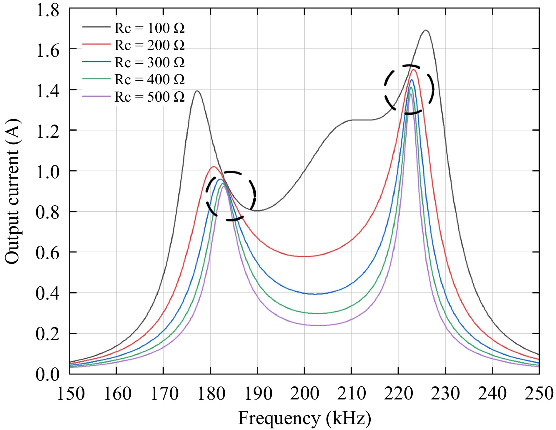
Figure 4.
Four-Coil WPT system output current versus frequency curve.
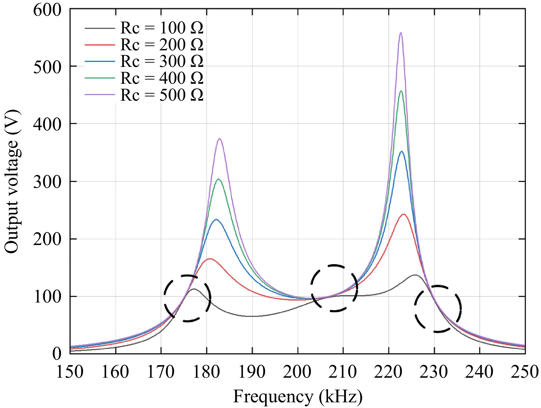
Figure 5.
Four-coil WPT system output voltage versus frequency curve.
As shown in Figs 4 and 5, this four-coil WPT system exhibits two constant current frequencies and three constant voltage frequencies, all marked in the figures. At these critical frequencies, the system ensures either constant voltage or constant-current output characteristics.
Based on the above equations[15], the specific values of the constant-current and constant-voltage operating frequencies for the four-coil WPT system can be calculated, as shown in Table 1. Here, CC1 and CC2 represent the first and second constant-current points, respectively, while CV1, CV2, and CV3 denote the first, second, and third constant voltage points, respectively.
Table 1. Four-Coil WPT system constant current and constant voltage frequency.
Current frequency Operating frequency (KHz) Voltage frequency Operating frequency(KHz) CC1 183 CV1 175 CC2 222 CV2 206 CV3 225 After determining the system's key frequencies, MATLAB simulations were used to calculate the transmission efficiency at each frequency for different load resistances, providing results for the five key frequencies.
The simulation results in Fig. 6 demonstrate that the transmission efficiency varies across different key frequencies, peaking at 206 kHz. Therefore, the system can adjust the input frequency based on the output load and the requirements for constant current, constant voltage, and efficiency.
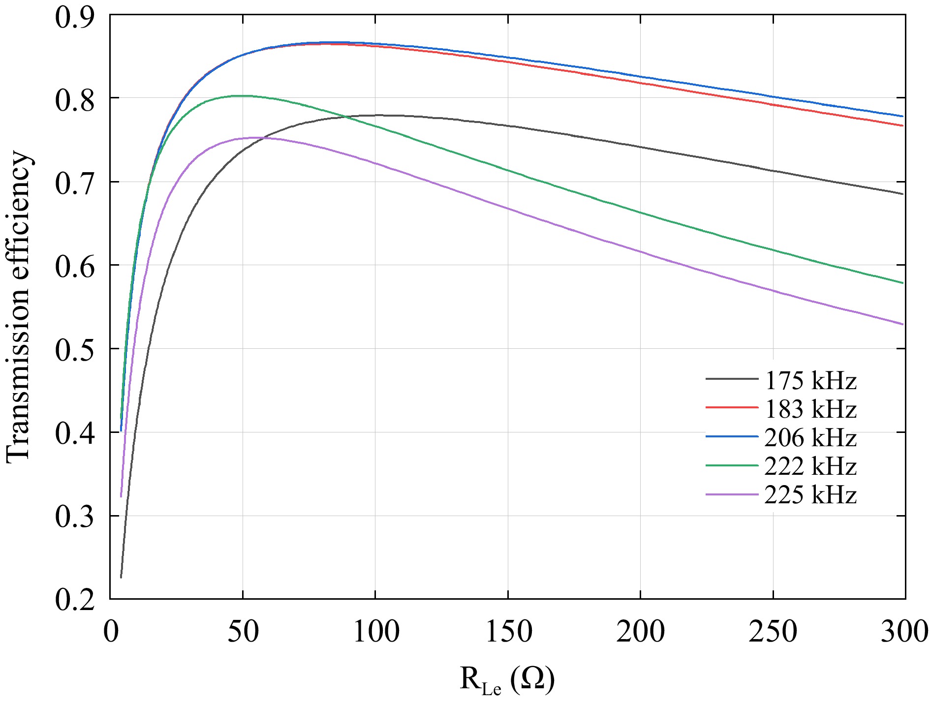
Figure 6.
System transmission efficiency at five critical frequencies.
Figure 7 below shows the dot-line graphs of the five key frequencies at multiple resistances. These diagrams clearly illustrate the resistance values corresponding to the highest efficiency at each frequency.
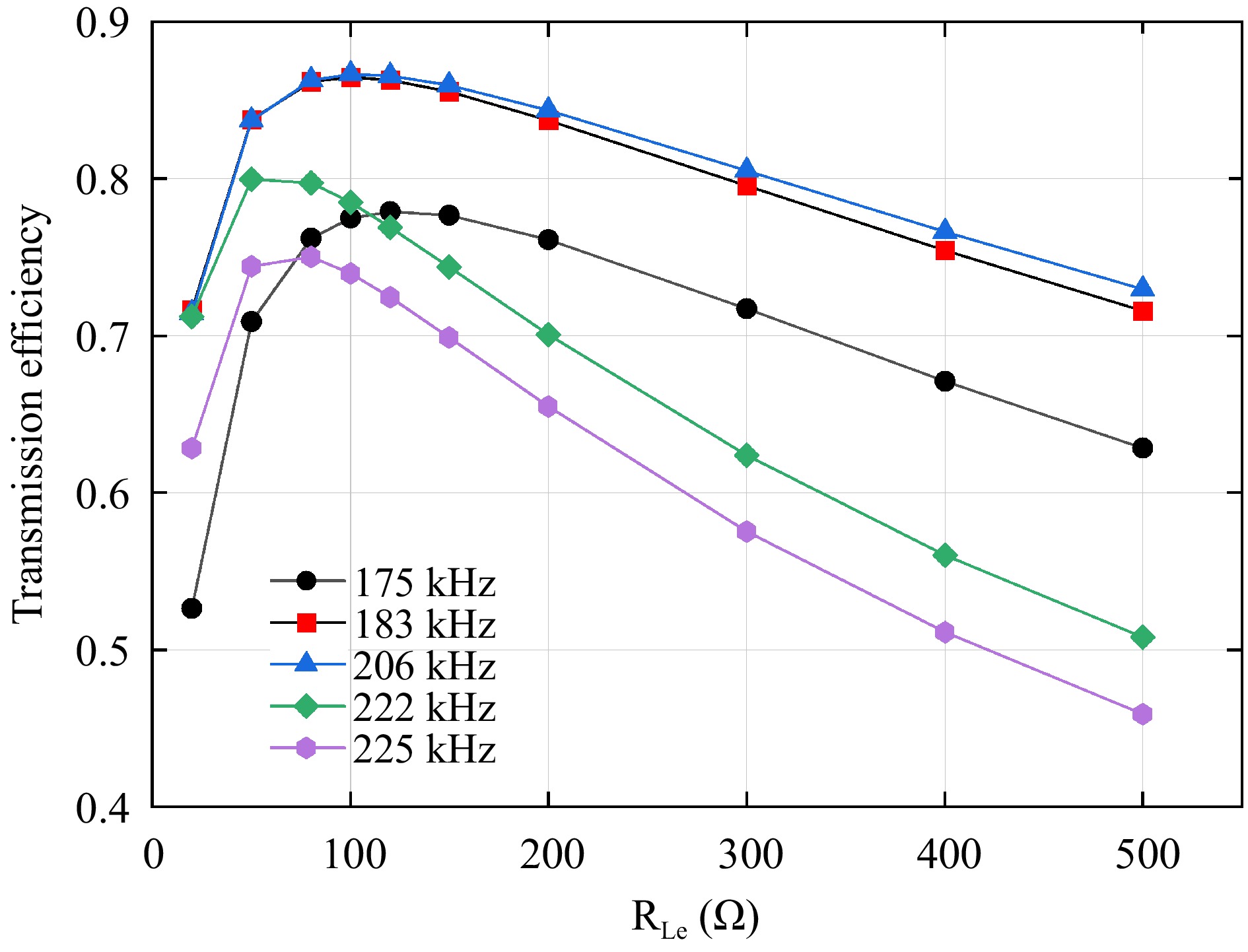
Figure 7.
Dot plot of efficiency at five key frequencies.
The efficiency dot-line diagram shows that when the system load resistance ranges between 80 and 100 Ω, the transmission efficiency at the five key frequencies remains relatively high. Specifically, the efficiency reaches 86.67% at 206 kHz, while the efficiencies at the other four frequencies also exceed 75%.
In practical experiments, the phase difference between the inverter's output voltage and current varies with the load resistance, resulting in imprecise implementation of zero-voltage switching (ZVS) at the 183 kHz frequency. If the system does not operate under ZVS conditions, the power losses increase significantly. At 206 kHz, simulation results indicate that a constant-voltage output cannot be achieved. Therefore, neither of these two frequencies can be selected when a low-loss operation or constant-voltage output is required, and the choice must be made among the remaining three frequencies. This facilitates the selection of the most efficient frequency based on load variations, thereby demonstrating the necessity of employing a switched-capacitor matrix.
The switched capacitor matrix proposed in this paper demonstrates remarkable applicability in WPT systems due to its unique dynamic reconfigurability. This technical solution is compatible with multi-relay WPT systems of any topology and effectively addresses resonance point deviation caused by frequency splitting phenomena.
-
To address the impact of input frequency changes on the system's resonant state, this study designs a multi-capacitance matrix based on MOSFET switches. By combining capacitors of different values in series and parallel, this matrix flexibly adjusts the equivalent capacitance of the CP1 component, ensuring the system remains in resonance as the input frequency changes. Although transmission efficiency differs across frequencies, load resistors exhibit varying efficiencies at different frequencies. To better adapt to these variations, the multi-capacitor matrix allows for convenient reconfiguration of capacitance after load adjustments, thereby optimizing system performance and ensuring optimal transmission results under diverse operating conditions.
Figure 8 illustrates the schematic diagram of the CP1 switched-capacitor matrix, where SW1, SW2, SW3, SW4, SW5, and SW6 are MOSFET switches, and CZ1, CZ2, and CZ3 are fixed-value capacitors. According to (1), the required resonant capacitance is calculated based on the obtained key frequencies. When the system's input frequency changes, the resonant capacitance value at the key frequency also changes. This study employs a switched-capacitor matrix method, where the equivalent capacitance is adjusted through the series-parallel combination of fixed capacitors in the matrix to match the resonant capacitance required by the current input frequency, ensuring high-efficiency transmission.
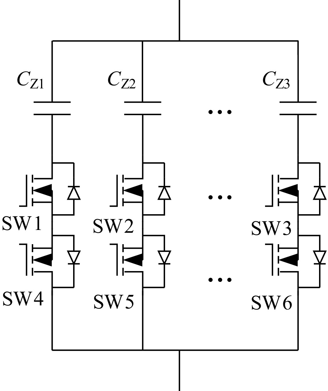
Figure 8.
Schematic diagram of switched capacitor matrix.
Through precise timing control, SCC ensures that no more than two parallel paths are conducted simultaneously during operation. This selective conduction mechanism significantly reduces the system's equivalent on-resistance while concentrating switching losses within a limited number of active branches. Furthermore, by optimizing the MOSFET driver circuit design and employing low-loss capacitors, additional losses are effectively mitigated, enabling the system to achieve high-efficiency power transfer.
The four operating modes of this switched-capacitor matrix are as follows:
Mode 1: When the upper MOSFET is turned on and the lower MOSFET is off, current can flow forward (from top to bottom) through the fixed capacitor, the upper MOSFET switch, and the diode connected to the lower switch, enabling the capacitor to function. However, if the current flows in an opposite direction, it is blocked and cannot operate.
Mode 2: When neither the upper nor the lower MOSFET is conducting, the system is in an open-circuit state.
Mode 3: When the lower MOSFET is turned on and the upper MOSFET is off, current can flow in reverse (from bottom to top) through the lower MOSFET switch, the diode connected to the upper switch, and the fixed capacitor, enabling the capacitor to function. However, if the current reverses again, it is blocked and cannot operate.
Mode 4: When both the upper and lower MOSFETs are turned on, the current can flow in both forward and reverse directions, allowing the system to operate normally.
Since this is an AC system, two reverse-series MOSFETs can control the current and prevent backflow, thereby protecting the entire system.
Figure 9 shows the four operating modes of a branch in the switched-capacitor matrix.
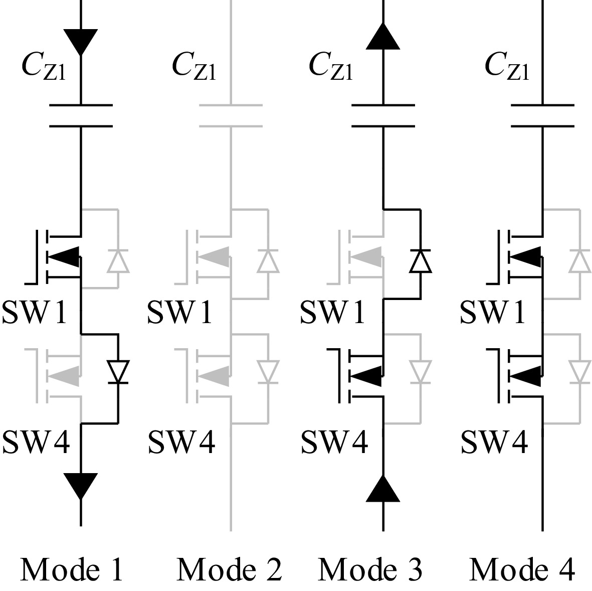
Figure 9.
Four operation modes of switched capacitor matrix.
The switched-capacitor matrix imposes relatively low timing requirements because its channel switching operates non-real-time, controlling each path's on/off state through MOSFET switch regulation. Each MOSFET switch is connected to a dedicated driver circuit, with the STM32F407ZGT6 microcontroller providing PWM signals to these driver circuits for switch control. The STM32F407ZGT6 firmware implements a key-press interface to sequentially switch PWM output paths across predefined frequencies (starting at 175 kHz), cycling ascendingly to activate corresponding drivers. The selected MOSFET stays on until the next frequency change.
To simplify the experimental design, the current research phase focuses exclusively on validating the switched compensation capacitors topology and control methodology, deliberately excluding efficiency monitoring to avoid measurement-induced parameter interference. Subsequent studies will incorporate output-side monitoring equipment for complete efficiency characterization. The control block diagram is shown in Fig. 10.
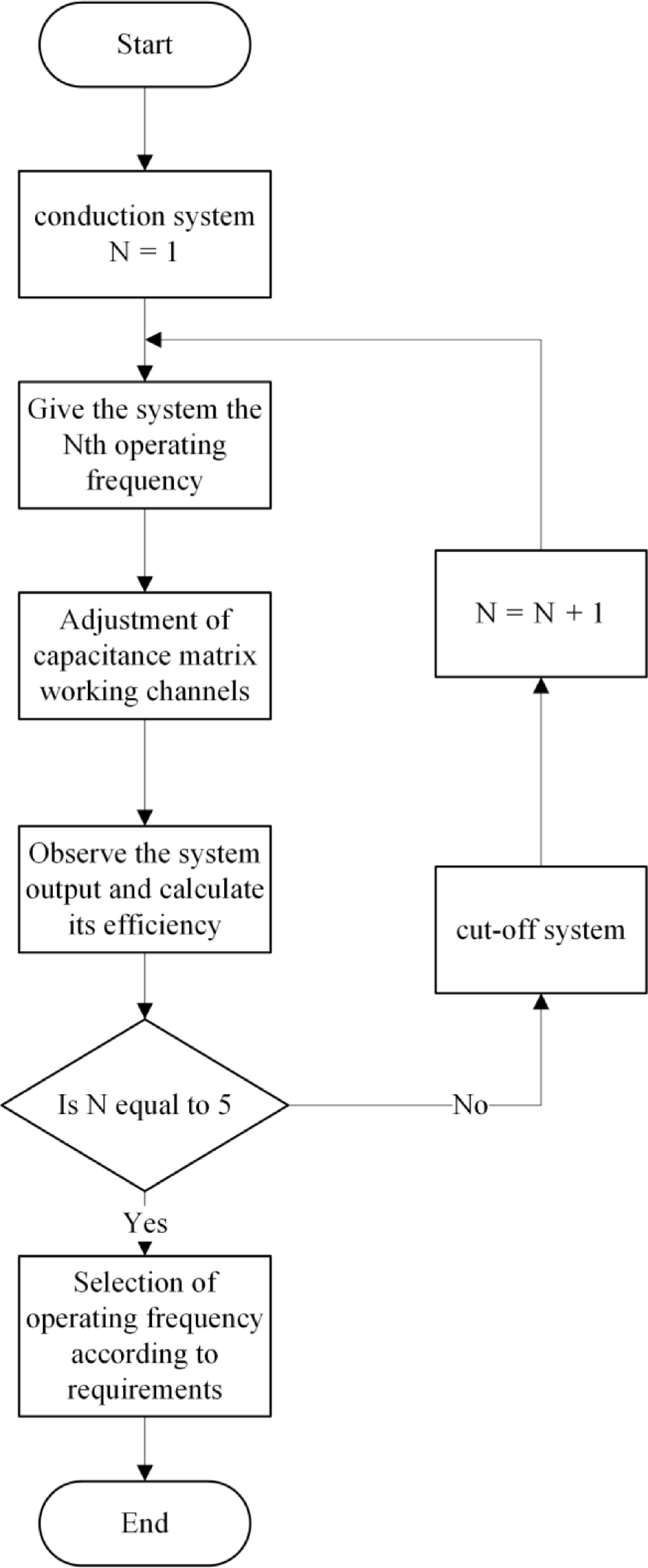
Figure 10.
System control block diagram.
Utilizing the series-parallel relationships of capacitors and combining capacitors with different capacitance values, the equivalent capacitance is adjusted to the value required for system resonance. When the input frequency is applied, a trigger signal is sent to the MOSFET switch connected in series with the resonant capacitor, which is turned on and ensures the system remains in resonance. This offline switching method enables faster and more precise identification of peak efficiency compared to real-time switching, which demonstrates inferior performance in maximum efficiency tracking.
-
The capacitance values of each fixed-value capacitor in Fig. 8 are shown in Table 2, and the required resonant capacitance capacitance values at each critical frequency and the selection in the corresponding capacitance matrix are shown in Table 3.
Table 2. Values of the fixed capacitances in the capacitance matrix.
Capacitance number Capacitance value (nF) CZ1 12 CZ2 12 CZ3 6.8 CZ4 27 CZ5 22 CZ6 2.7 Table 3. Values of resonant capacitance at different key frequencies.
Frequency (KHz) Selection of capacitance matrix 175 CZ4 183 CZ1, CZ2 206 CZ5 222 CZ1, CZ3 225 CZ1, CZ6 The specific parameters of the components of the whole system during simulation are shown in Table 4.
Table 4. Element parameters of four-coil multi-relay compensation network.
Parameters Values U (V) 100 LP (μH) 30 LP1, L1, L2, LS (μH) 365 MP1, M12, M2S (μH) 68 MP2, M1S (μH) 22 MPS (μH) 10 CP (nF) 1.9 C1, C2, CS (nF) 1.73 CL (μF) 2 In the simulation process, the value of CP1 is adjusted as the input frequency of the system is changed, so that the system remains in a resonant state. At this frequency, the transmission efficiency of the system reaches its highest level.
Figure 11 illustrates an experimental platform built based on the four-coil LCC-S multi-relay WPT system shown in Fig. 1. The input voltage was set to 40 V.
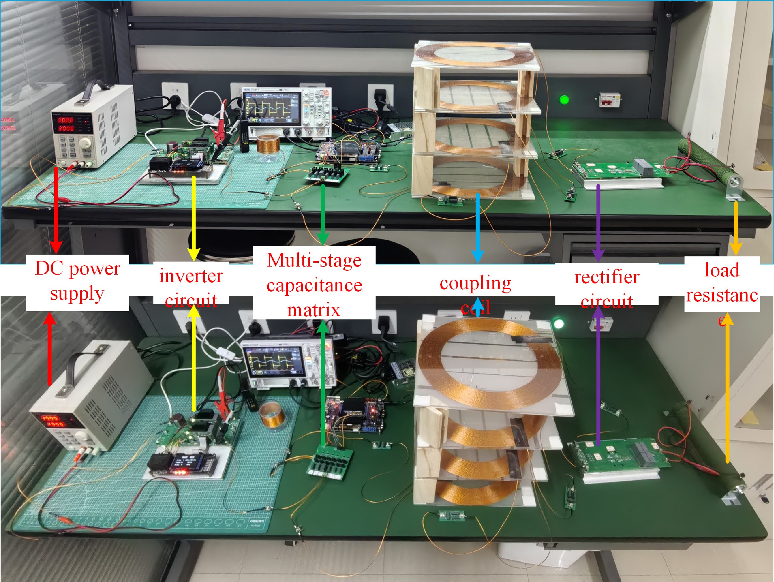
Figure 11.
LCC-S type multi-relay WPT system experimental device.
The experimental waveforms confirm that the system can achieve ZVS (zero-voltage switching) and constant current/voltage output at key frequencies. Figure 12 shows the input waveform of the compensation network. Figure 13 shows the system's output waveforms at these five key frequencies.
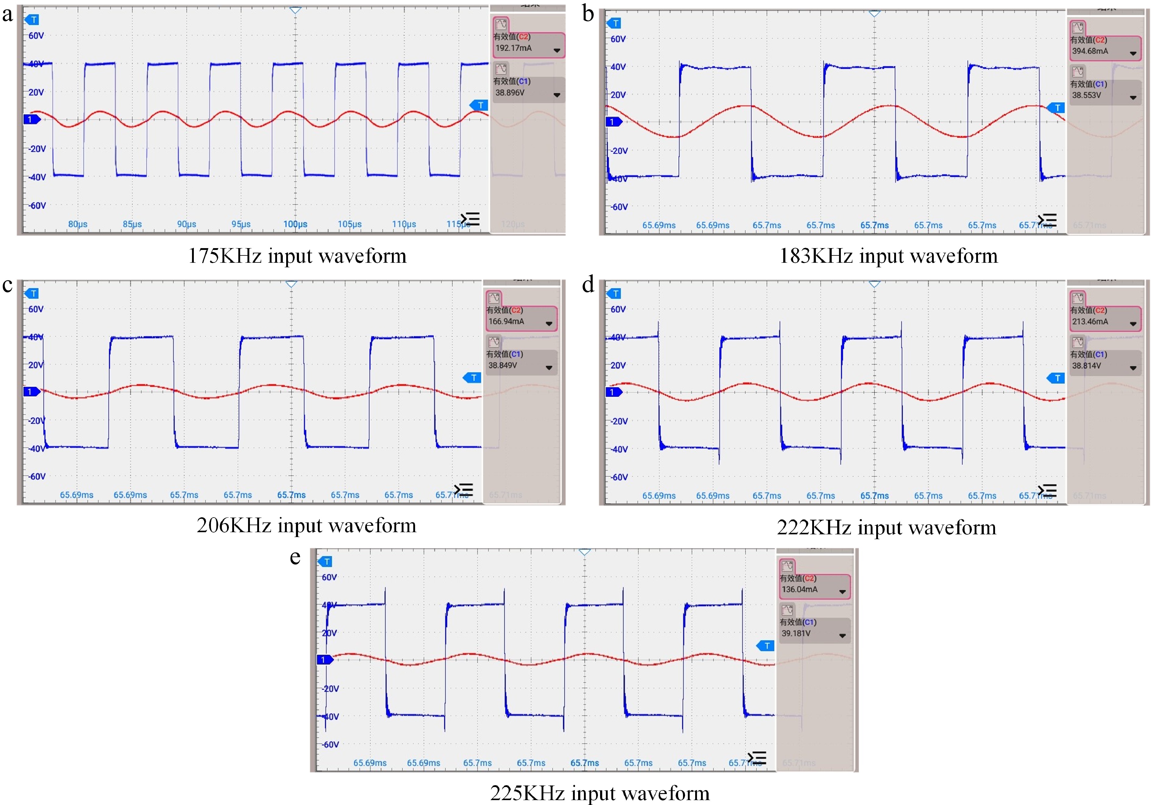
Figure 12.
Input waveform of experimental equipment.
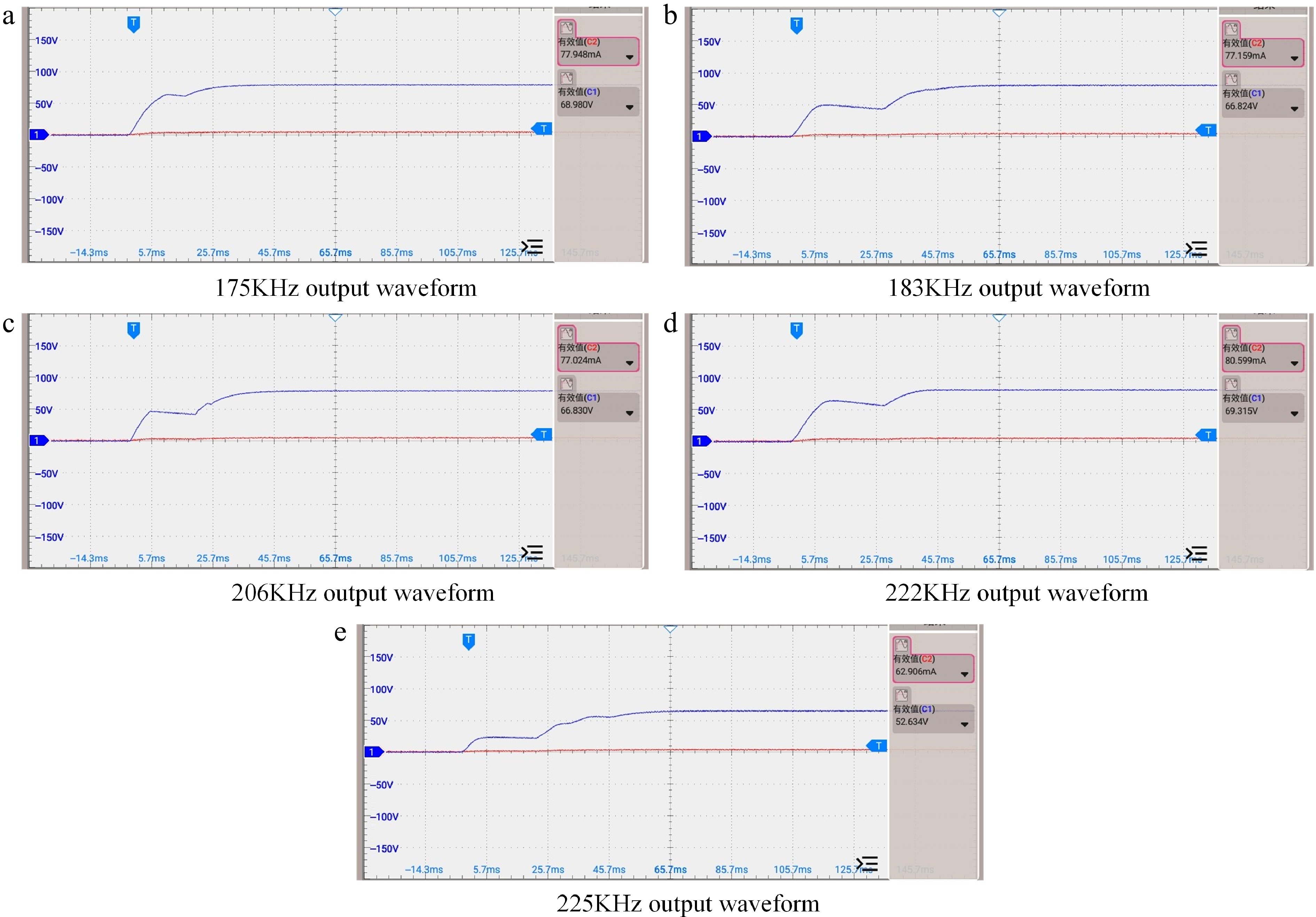
Figure 13.
Output waveform of experimental equipment.
Based on the comparison of simulation and experimental data, the system's simulated efficiency is higher than the experimental results because the simulation does not account for losses from measuring instruments.
Table 5 presents the transmission efficiency results from the hardware experiments.
Table 5. Experimental transmission power and efficiency of four-coil WPT system at different input frequencies.
Frequency (KHz) Equivalent load (Ω) Transmission efficiency 175 100 71.94% 183 100 42.07% 206 100 79.37% 222 100 71.94% 225 100 62.11% -
In this paper, a mathematical model of a four-coil wireless power transfer (WPT) system is established based on circuit theory, and the system's output characteristics are thoroughly analyzed to determine its constant voltage and constant current frequencies. However, in the four-coil LCC-S compensation network WPT system, changes in the input frequency can lead to resonant capacitance mismatch, significantly reducing transmission efficiency. An innovative solution is proposed to address this issue: a capacitance matrix method is introduced to optimize the compensation capacitance of the four-coil WPT system.
Finally, an experimental platform for this system was constructed, and the resonant capacitor CP1 in the four-coil WPT system was improved. The experimental results demonstrate that the enhanced CP1 can more conveniently match the corresponding resonant capacitor as the input frequency changes. This effectively ensures the system's transmission efficiency and verifies the feasibility and effectiveness of the proposed method.
This work was supported by the National Natural Science Founda-tion of China under (Grant No. 52307204), the Natural Science Basic Research Program of Shaanxi under (Grant No. 2024JC-YBQN-0481) and the Young Talent Fund of Xi'an Association for Science and Technology under (Grant No. 0959202513080).
-
The authors confirm their contributions to the paper as follows: study conception and design: Hou X, Yang M, Shi Y, Yu Z, Zhao Z; data collection: Yang M; analysis and interpretation of results, draft manuscript preparation: Hou X, Yang M. All authors reviewed the results and approved the final version of the manuscript.
-
All data analyzed during this study are available from the corresponding author upon reasonable request.
-
The authors declare that they have no conflict of interest.
- Copyright: © 2025 by the author(s). Published by Maximum Academic Press, Fayetteville, GA. This article is an open access article distributed under Creative Commons Attribution License (CC BY 4.0), visit https://creativecommons.org/licenses/by/4.0/.
-
About this article
Cite this article
Hou X, Yang M, Shi Y, Yu Z, Zhao Z. 2025. Efficiency enhancement of multi-relay wireless power transfer system using switched compensation capacitors. Wireless Power Transfer 12: e024 doi: 10.48130/wpt-0025-0018 

Efficiency enhancement of multi-relay wireless power transfer system using switched compensation capacitors
- Received: 08 April 2025
- Revised: 07 May 2025
- Accepted: 14 May 2025
- Published online: 12 September 2025
Abstract: Multi-relay wireless power transfer (WPT) systems are increasingly used in power supply applications for high-voltage transmission line monitoring due to their extended transmission range. However, such systems face challenges from frequency-splitting phenomena, where multiple resonant frequencies render fixed compensation networks ineffective. To address this, a switchable compensation capacitor matrix is proposed to replace the resonant capacitor in LCC-S compensation networks. First, the transmission efficiency and constant current/voltage output characteristics of a four-coil multi-relay WPT system with LCC-S compensation are investigated. Then, the transmitter-side resonant capacitor is replaced with a switchable capacitor matrix to achieve stable output performance. Experimental results demonstrate that the modified system can dynamically adjust compensation capacitance according to input frequency variations, effectively matching the required resonant conditions. The feasibility of the proposed method is verified through a four-coil multi-relay WPT system prototype implementation, showing improved frequency adaptability while maintaining system efficiency.