


-
Magnetic coupling is one of the main methods of WPT. Due to limitations in installation space or the complex and dynamic nature of real-world applications, flat coil structures are the primary coupling mechanism used[1−4]. However, in practical applications, a critical issue that WPT systems face is the misalignment of the coupling mechanism[5,6]. Since the primary side coil is usually fixed in position, while the secondary side coil is installed in the load device, this leads to challenges in fixing the secondary side coil's position. Consequently, the secondary coil undergoes bidirectional positional displacement—laterally (X-axis) and longitudinally (Y-axis)—owing to dynamic device movement during operational cycles, thereby necessitating enhanced misalignment tolerance in multi-dimensional spatial configurations. Such misalignment directly alters the relative position between the coupling coils, resulting in significant changes to key electromagnetic parameters such as mutual inductance and self-inductance, which in turn affect the system's stability and power transfer efficiency[7]. Especially in systems lacking sufficient misalignment tolerance, the shift in the magnetic coupling mechanism could cause serious issues, such as reduced power transfer capability, circuit detuning, and increased energy loss in the transmission system[8]. Enhancing the misalignment tolerance of WPT systems constitutes a key research frontier, as it critically governs both operational reliability and energy efficiency. This necessitates maintaining stable power transfer efficiency during bidirectional misalignment in both X-axis and Y-axis directions under dynamic operating conditions.
Currently, many scholars have proposed and implemented various techniques to improve the misalignment tolerance of magnetic coupling mechanisms. These techniques primarily focus on four aspects: control strategies, compensation topologies, mode switching, and magnetic coupler optimization, to enhance the misalignment resistance of load devices in WPT systems[9,10]. However, using control strategies, compensation topologies, and mode switching to improve the misalignment tolerance of magnetic coupling mechanisms often increases the complexity of WPT system control, which leads to a significant increase in the number of passive components in the system. This, in turn, results in higher system costs and larger overall sizes, potentially limiting the applicability of WPT systems. Therefore, this study focuses on optimizing the magnetic coupling mechanism to enhance the misalignment tolerance of WPT systems. Through structural refinement of the magnetic coupler, the system's misalignment tolerance capability is significantly improved in both X-axis and Y-axis directions. Earlier researchers describe an innovative coupling structure—the DD coil, which consists of two D-shaped coils wound in different directions, connected in series and placed side by side[11]. This structure effectively ensures that the majority of the magnetic flux forms a closed loop between the primary and secondary coils, thereby improving the system's coupling coefficient. Compared to circular coils of the same size, the DD coil generates a larger effective charging area. Previous researchers proposed a same-plane orthogonal double DD magnetic coupling mechanism based on QDQP and designed a corresponding LCC-S composite compensation network to stabilize the system output voltage when the magnetic coupling mechanism is misaligned[12]. Previous work presents a misalignment-resistant wireless power transfer system based on DQDD coils and builds a 1 kW prototype with a 120 mm spacing, verifying the misalignment-resistant characteristics of the magnetic coupling mechanism[13]. Other researchers propose a coil structure that adds a Q-shaped coil to the DD coil[14]. The added Q-shaped coil is orthogonal to the DD coil, forming a DDQ magnetic coupling mechanism that compensates for the inductive blind spots present during misalignment in the DD coil. A dual-layer DD coil, where all D-shaped coils are wound in reverse, effectively increasing the effective charging area of the wireless power transfer system[15]. Existing solutions face dual challenges of compromised misalignment tolerance in both X-axis and Y-axis directions, compounded by excessive weight of magnetic cores. Existing winding configurations for magnetic coupling mechanisms predominantly employ tight winding due to the manufacturing challenges associated with loose winding techniques. This tight-wound structure results in a magnetic flux density distribution characterized by intensified field concentrations at the peripheral regions and a discernible reduction in the central area. However, loose-wound coils exhibit inter-turn spacing that shifts magnetic flux density concentration toward the central region, resulting in a more spatially homogeneous distribution. This characteristic effectively compensates for the central flux density deficiency observed in tight-wound coil configurations[16].
This study addresses the issues of multiple directional misalignments in magnetic coupling mechanisms for WPT systems, which lead to fluctuations in equivalent mutual inductance, as well as the high cost and weight of coil magnetic cores. A misalignment-resistant WPT system using a loose winding method, featuring a dual-layer vertical DD (Double Vertical DD, DVDD) coil magnetic coupling mechanism and a new type of magnetic core, is proposed. This approach synergistically enhances the misalignment tolerance of WPT systems in both X-axis and Y-axis directions, while simultaneously resolving the inherent drawbacks of conventional magnetic cores regarding excessive weight and prohibitive cost. The designed DVDD coil consists of two pairs of orthogonal DD coils, which simplifies the decoupling characteristics. The mathematical modeling and analysis of the DVDD magnetic coupling mechanism are provided, and the output characteristics of the WPT system with the LCC-S compensation topology are derived. Finite element simulations using COMSOL were conducted to compare the equivalent mutual inductance variations and the coupling coefficient stability of the DVDD mechanism with other magnetic coupling mechanisms. Finally, a prototype wireless power transfer system using the DVDD magnetic coupling mechanism was constructed, and the misalignment resistance and the feasibility of a lightweight magnetic core were verified.
-
Ordinary rectangular or circular coils are unipolar coils, with the magnetic field direction being unidirectional along the z-axis normal vector. In contrast, the differential dipole configuration exhibits dual-polarity characteristics, with magnetic flux lines entering one rectangular side and exiting from the other. As shown in Fig. 1, the direction of the magnetic flux lines, represented by the yellow dashed lines, is orthogonal to the radial axis direction, indicated by the red dashed lines.
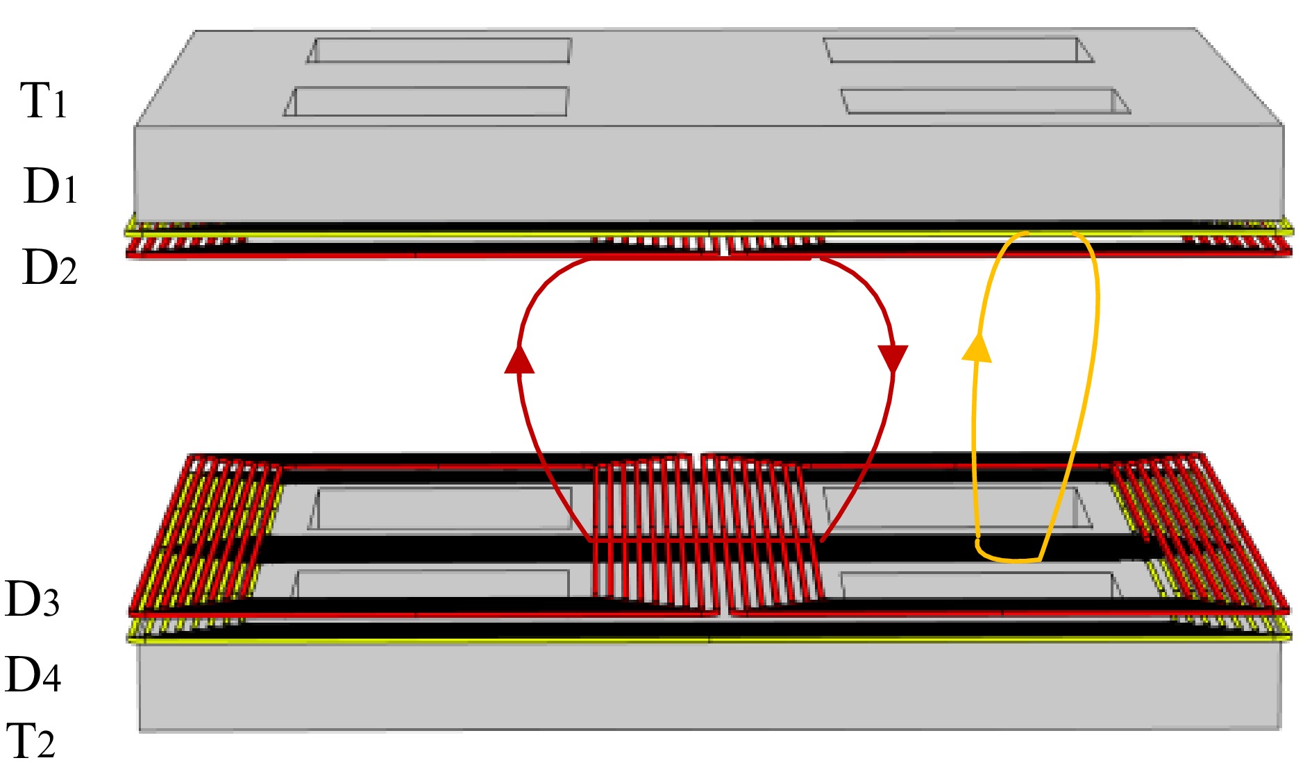
Figure 1.
Magnetic field diagram of the DVDD magnetic coupling mechanism.
By leveraging their orthogonal characteristics, when two DD coils are arranged perpendicularly with orthogonal alignment, their magnetic field lines remain mutually perpendicular, thereby exhibiting no mutual interference. As illustrated in Fig. 1, the red and yellow DD coils demonstrate this vertical orthogonal configuration, with their respective magnetic flux lines maintaining strict perpendicularity. The four DD coils are labeled sequentially from top to bottom as D1, D2, D3, and D4, with T1 and T2 denoting the primary and secondary magnetic cores, respectively. Due to the non-interfering nature of their magnetic fields, each coil pair demonstrates selective coupling: the D1 coil couples exclusively with the D4 coil, while the D2 coil interacts solely with the D3 coil.
As shown in Fig. 2, the schematic diagram of the DVDD coil magnetic coupling mechanism is presented. In Fig. 2a, the DVDD coil consists of two transmitting coils and two receiving coils to form the magnetic coupling mechanism. The coil width is W1, the length is L1, and the number of turns is n, with the fixed resin board width W2 and length L2. Both the transmitting and receiving coils are stacked with two mutually perpendicular DD coils, as shown in Fig. 2b. The transmitting coils are labeled from top to bottom as D1 coil, primary winding resin channel plate, D2 coil, and ferrite magnetic core. Let h1, h2, h3, and h4 denote the thicknesses of the D1 coil, primary winding resin channel plate, D2 coil, and ferrite magnetic core, respectively, while d represents the coil separation distance. The D1 and D2 coils are each composed of two DD coils with the same length, width, and number of turns connected in series. The receiving coils are labeled from top to bottom as ferrite magnetic core, D3 coil, secondary side resin groove plate, and D4 coil, where the D3 and D4 coils have the same number of turns as the transmitting coils.
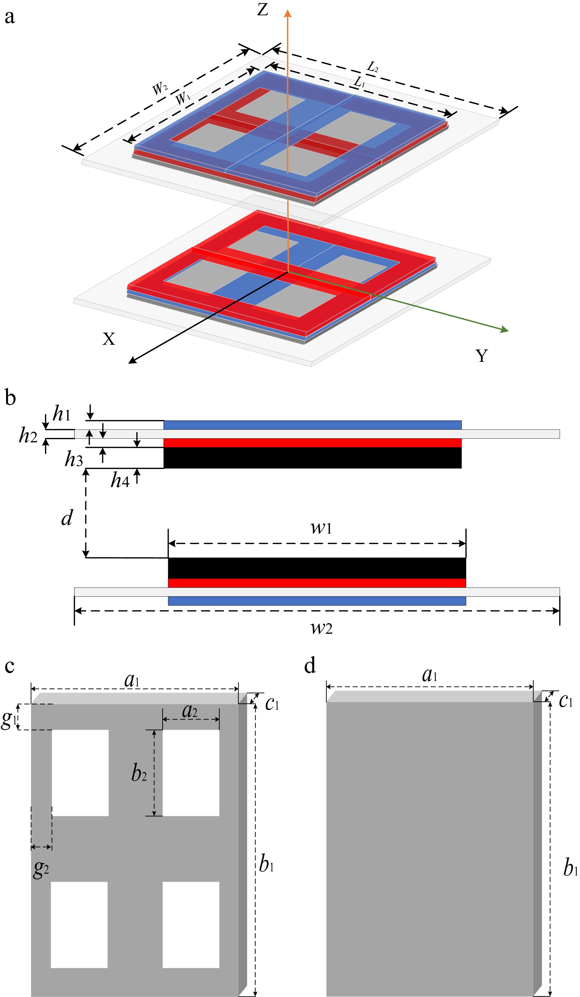
Figure 2.
Schematic diagram of the DVDD magnetic coupling mechanism. (a) 3D model of the DVDD magnetic coupling mechanism. (b) Front view of the DVDD magnetic coupling mechanism. (c) New-type magnetic core structure. (d) Full-coverage magnetic core structure.
Figure 2c, d shows the schematic diagrams of the full-coverage magnetic core and the new-type magnetic core in the DVDD coil magnetic coupling mechanism. In Fig. 2c, the new-type magnetic core structure is designed in a cross shape to reduce the amount of magnetic core used while maintaining the magnetic field intensity at the center overlap position of the coils. Both the new-type magnetic core and the full-coverage magnetic core structure use PC95 ferrite, with identical length, width, and thickness, denoted as a1, b1, and c1, respectively. The internal rectangular length of the new-type magnetic core is a2, with a width of b2, and the distance from length a1 is g1, while the distance from width b2 is g2. The specific parameter values are provided in Table 1.
Table 1. Relevant parameters of the DVDD magnetic coupling mechanism.
Parameters Values (mm) Parameters Values (mm) W1 120 a1 120 W2 200 a2 30 L1 150 b1 150 L2 200 b2 40 h1 1.53 g1 15 h2 2 g2 12 h3 1.53 c1 10 h4 10 Analysis of the DVDD wireless power transfer system
-
As shown in Fig. 3, the wireless power transfer system using a dual-vertical DD coil magnetic coupling mechanism consists of six main parts: the DC power supply, primary full-bridge inverter circuit, LCC-S compensation network, primary and secondary coils, secondary bridge rectifier circuit, output filtering, and equivalent load resistance. The DC power supply is provided by Udc in Fig. 3. The primary full-bridge inverter circuit is composed of four MOSFETs labeled Q1 to Q4. The LCC-S compensation network consists of L1, R1, C1, C2, and C3, forming the resonant network. The primary and secondary coils each consist of a pair of double-layered, mutually perpendicular DD coils. L2, L3, L4, L5, R2, and R3 represent the self-inductance and resistance of the primary and secondary coils, respectively. Current I refers to the input current of the primary full-bridge inverter circuit, while currents I1 and I2 represent the currents flowing through the primary and secondary coils. The secondary bridge rectifier circuit is made up of four diodes (VD1 to VD4), and C0 is the output filtering capacitor of the rectifier circuit. UIN, UOUT, Udc, Meq, RL, and Req denote the input voltage of the primary-side coil, output voltage at the secondary-side coil, DC voltage, equivalent mutual inductance, load resistance, and equivalent load resistance on the secondary side, respectively.
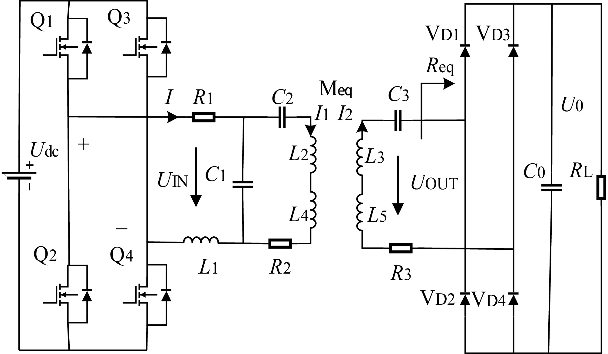
Figure 3.
Circuit diagram of a wireless power transfer system based on the DVDD magnetic coupling mechanism.
The wireless power transfer system converts the DC power supply Udc into a high-frequency AC voltage UIN by controlling the driving signals of the high-frequency inverter, which consists of four MOSFETs. The high-frequency AC voltage is then supplied to the transmitting coil of the primary DVDD magnetic coupling mechanism through the primary LCC resonant compensation network. After the receiving coil on the secondary side receives the power from the primary side, it is rectified through a series compensation connected to a rectifier circuit composed of four semiconductor diodes. Finally, the output is filtered and supplied to the equivalent load.
Mutual coupling exists among the four DD coils, where the mutual inductances between coil pairs are denoted as ML2L3, ML2L5, ML3L4, and ML4L5, representing the magnetic interactions between coils L2 and L3, L2 and L5, L3 and L4, and L4 and L5, respectively.
Given that coil pairs L2, L3 and L4, L5 are mutually orthogonal, the mutual inductances ML2L3 and ML4L5 are considered negligible and can be mathematically expressed as ML2L3 = ML4L5 ≈ 0. The equivalent mutual inductance Meq is consequently defined to characterize the magnetic coupling behavior of the DVDD structure[17].
$ {M_{{\text{eq}}}} = \sqrt {{M_{L{\text{2}}L{\text{5}}}}^2 + {M_{L3L4}}^2} $ (1) In the LCC-S resonant compensation network shown in the Fig. 3, applying KVL gives:
$ \left\{ \begin{gathered} {U_{{\text{IN}}}} = \left({R_1} + \dfrac{1}{{j\omega {C_1}}} + j\omega {L_1}\right)I - \dfrac{1}{{j\omega {C_1}}}{I_1} \\ 0 = - \dfrac{1}{{j\omega {C_1}}}I + \left({R_2} + \dfrac{1}{{j\omega {C_2}}} + j\omega {L_2} + j\omega {L_4} + \dfrac{1}{{j\omega {C_1}}}\right){I_1} - j\omega {M_{{\text{eq}}}}{I_2} \\ 0 = j\omega {M_{{\text{eq}}}}{I_1} - \left({R_3} + \dfrac{1}{{j\omega {C_3}}} + j\omega {L_3} + j\omega {L_5} + {R_{{\text{eq}}}}\right){I_2} \\ \end{gathered} \right. $ (2) In the resonant state, the following condition is satisfied:
$ \omega = \sqrt {\dfrac{1}{{{C_1}{L_1}}}} = \sqrt {\dfrac{1}{{{C_2}({L_2} + {L_4} - {L_1})}}} = \sqrt {\dfrac{1}{{{C_3}({L_3} + {L_5})}}} $ (3) From this, the currents I, I1, and I2 are derived as:
$ \left\{ \begin{gathered} I = \dfrac{{\left[ {{\omega ^2}{M_{{\text{eq}}}}^2 + {R_2}({R_3} + {R_{{\text{eq}}}})} \right]{U_{\text{I}}}_{\text{N}}}}{{({\omega ^2}{L_1}^2 + {R_1}{R_2})({R_3} + {R_{{\text{eq}}}}) + {\omega ^2}{M_{{\text{eq}}}}^2{R_1}}} \\ {I_1} = \dfrac{{ - j\omega {M_{{\text{eq}}}}{L_1}({R_3} + {R_{{\text{eq}}}}){U_{{\text{IN}}}}}}{{({\omega ^2}{L_1}^2 + {R_1}{R_2})({R_3} + {R_{{\text{eq}}}}) + {\omega ^2}{M_{{\text{eq}}}}^2{R_1}}} \\ {I_2} = \dfrac{{{\omega ^2}{M_{{\text{eq}}}}{L_1}{U_{{\text{IN}}}}}}{{({\omega ^2}{L_1}^2 + {R_1}{R_2})({R_3} + {R_{{\text{eq}}}}) + {\omega ^2}{M_{{\text{eq}}}}^2{R_1}}} \\ \end{gathered} \right. $ (4) Assuming that:
$ D = ({\omega ^2}{L_1}^2 + {R_1}{R_2})({R_3} + {R_{{\text{eq}}}}) + {\omega ^2}{M_{{\text{eq}}}}^2{R_1} $ (5) Consequently, the aforementioned system of equations can be expressed as:
$ \left\{ \begin{gathered} I = [{\omega ^2}M{\text{e}}{{\text{q}}^{\text{2}}} + {R_2}({R_3} + {R_{{\text{eq}}}})]\dfrac{{{U_{{\text{IN}}}}}}{D} \\ {I_1} = - j\omega M{\text{eq}}{L_1}({R_3} + {R_{{\text{eq}}}})\dfrac{{{U_{{\text{IN}}}}}}{D} \\ {I_2} = {\omega ^2}M{\text{eq}}{L_1}\dfrac{{{U_{{\text{IN}}}}}}{D} \\ \end{gathered} \right. $ (6) From this, the output power P0 and input power P1 of the wireless power transfer system are obtained as:
$ {P_{\text{0}}} = {I_2}^2{R_{{\text{eq}}}} = {\omega ^4}M{\text{e}}{{\text{q}}^2}{L_1}^2{R_{{\text{eq}}}}\dfrac{{U{\text{IN}}}}{{{D^2}}} $ (7) $ {P_1} = I{U_{{\text{IN}}}} = [{\omega ^2}M{\text{e}}{{\text{q}}^{\text{2}}} + {R_2}({R_3} + {R_{{\text{eq}}}})]\dfrac{{U{\text{IN}}}}{D} $ (8) From Eqs (8) and (9), the system conversion efficiency η is obtained as:
$ \eta = \dfrac{{{P_{\text{0}}}}}{{{P_1}}} = \dfrac{{{\omega ^8}{M_{eq}}^4{L_1}^4{R_{{\text{eq}}}}^2}}{{D\left[ {{\omega ^2}{M_{eq}}^2 + {R_2}({R_3} + {R_{{\text{eq}}}})} \right]}} $ (9) From the above reasoning, it can be concluded that when the coils in the DVDD magnetic coupling mechanism experience misalignment, the mutual inductances Meq will fluctuate, which in turn affects the overall system performance. Therefore, by enhancing the misalignment resistance of the magnetic coupling mechanism and ensuring the stability of the mutual inductance, the overall performance of the system can be improved[18,19].
-
The degree of magnetic coupling between the transmitting coil and the receiving coil is an important manifestation of the misalignment resistance ability of the wireless power transfer system's magnetic coupling mechanism. During the misalignment of the transmitting and receiving coils, the degree of magnetic coupling is often measured by the coupling coefficient[20−22]. The DVDD magnetic coupling mechanism consists of two transmitting coils and two receiving coils. The coils on the same side are mutually perpendicular and orthogonal, so they are decoupled from each other. The equivalent coupling coefficient keq is:
$ {k_{{\text{eq}}}} = \sqrt {\dfrac{{{S_{{\text{u}}e1}} + {S_{ue2}}}}{{{S_{ua1}} + {S_{ua2}}}}} $ (10) In the equation, Sue1 represents the apparent power of the D1 layer coil in the dual-vertical DD transmitter, Sue2 denotes the apparent power of the D2 layer transmitter coil, while Sua1 and Sua2 correspond to the apparent power induced in the D3 and D4 layer receiver coils, respectively. These quantities characterize the energy transfer capability between the transmitter and receiver coils through inductive coupling. Since the two coils on the same side are decoupled from each other, the apparent powers of the D1 and D2 transmitter coils in the DVDD structure are given by:
$ {S_{{\text{ue1}}}} = {U_{L{\text{2}}}}{I_1} = j\omega {L_2}{I_1}^2 $ (11) $ {S_{{\text{ue2}}}} = {U_{L{\text{4}}}}{I_1} = j\omega {L_4}{I_1}^2 $ (12) The apparent powers of the D3 and D4 receiver coils in the DVDD structure are given by:
$ {S_{{\text{ua1}}}} = {U_{L{\text{3}}}}{I_2} = \dfrac{{{{(j\omega {M_{{\text{1D4D}}}}{I_1})}^2}}}{{j\omega {L_3}}} $ (13) $ {S_{{\text{ua2}}}} = {U_{L{\text{5}}}}{I_{\text{2}}} = \dfrac{{{{(j\omega {M_{{\text{2D3D}}}}{I_2})}^2}}}{{j\omega {L_5}}} $ (14) Since the adjacent DD coils in series on the same side have identical structural dimensions, their self-inductance values are considered to be nearly the same and can be approximated. Combining the above equations, the equivalent coupling coefficient keq of the magnetic coupling mechanism is derived as shown in Eq. (15), where Meq is the equivalent mutual inductance of the DVDD magnetic coupling mechanism.
$ {k_{{\text{eq}}}} = \dfrac{{{M_{{\text{eq}}}}}}{{\sqrt {{L_2}{L_3}} }} $ (15) Based on the above equivalent coupling coefficient, the expression for the Coupling Coefficient Retaining Ratio (CCRR) is[23]:
$ CCRR = \dfrac{{{k_{{\text{eqmis}}}}}}{{{k_{{\text{eq0}}}}}} $ (16) where, CCRR represents the Coupling Coefficient Retaining Ratio of the magnetic coupling mechanism, keq0 represents the equivalent magnetic coupling coefficient when the coupler is aligned, and keqmis represents the equivalent coupling coefficient when the coupler is misaligned. The larger the CCRR value, the stronger the misalignment resistance ability of the magnetic coupling mechanism.
Based on the derived equivalent coupling coefficient keq and Coupling Coefficient Retaining Ratio (CCRR), simulation analysis of the misalignment resistance characteristics of the DVDD coil magnetic coupling mechanism was performed using the COMSOL finite element analysis tool. As shown in Fig. 4, the schematic of the front and rear coil winding of the DVDD coil in COMSOL is depicted. The simulation was conducted in the COMSOL finite element simulation software with the following structural parameters: W1 = 120 mm, W2 = 150 mm, n = 8, d = 40 mm, a1 = 120 mm, b1 = 150 mm, a2 = 30 mm, b2 = 40 mm, g1 = g2 = 15 mm.
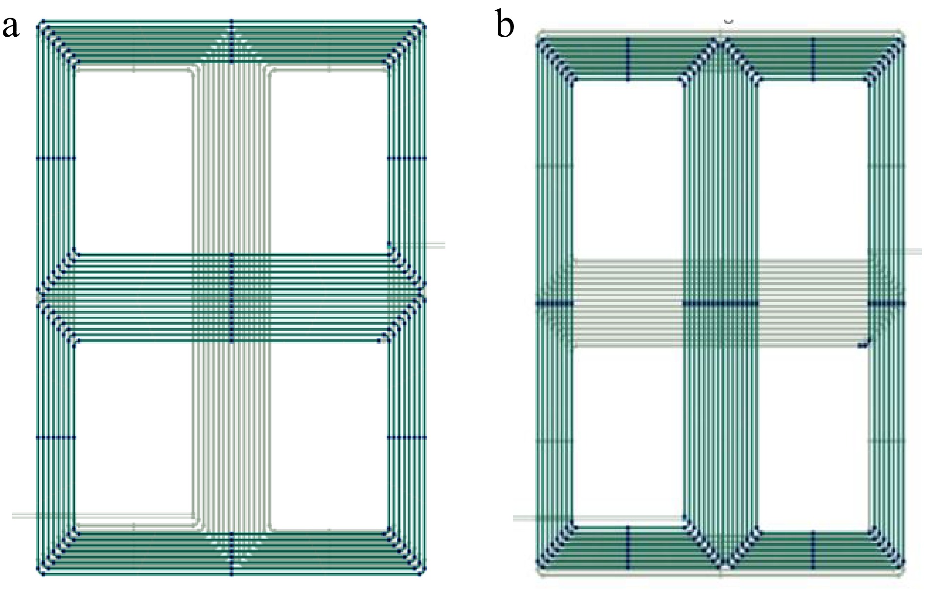
Figure 4.
Simulation model of DVDD coil in COMSOL. Schematic diagram of the (a) coil front view and (b) coil rear view.
As shown in Fig. 5, it presents the magnetic field distribution contour maps for a single DD coil magnetic coupling mechanism without a magnetic core, and for the DVDD coil magnetic coupling mechanism without a magnetic core, with a full-cover magnetic core, and with a new-type magnetic core. It is clear that after adding a magnetic core to the DVDD coil magnetic coupling mechanism, the magnetic field beneath the coil is shielded by the PC95 ferrite, making the magnetic field more concentrated and directing it towards the energy transfer direction. Under the same coil area and size, this significantly improves the self-inductance and mutual inductance values. Additionally, the magnetic field distribution for the new-type magnetic core is almost identical to that of the full-cover magnetic core. Table 1 lists the coupling coefficients and the volumes of magnetic cores used for the DVDD coil with two different magnetic core structures. The table clearly shows that the proposed magnetic core structure has a coupling coefficient almost identical to that of the full-cover magnetic core. Furthermore, the new-type magnetic core reduces the required magnetic core material by 26.6% compared to the full-cover magnetic core structure. This reduction in material usage not only maintains the original coupling strength but also contributes to weight reduction and cost savings. Therefore, the proposed magnetic core structure has significant practical value.
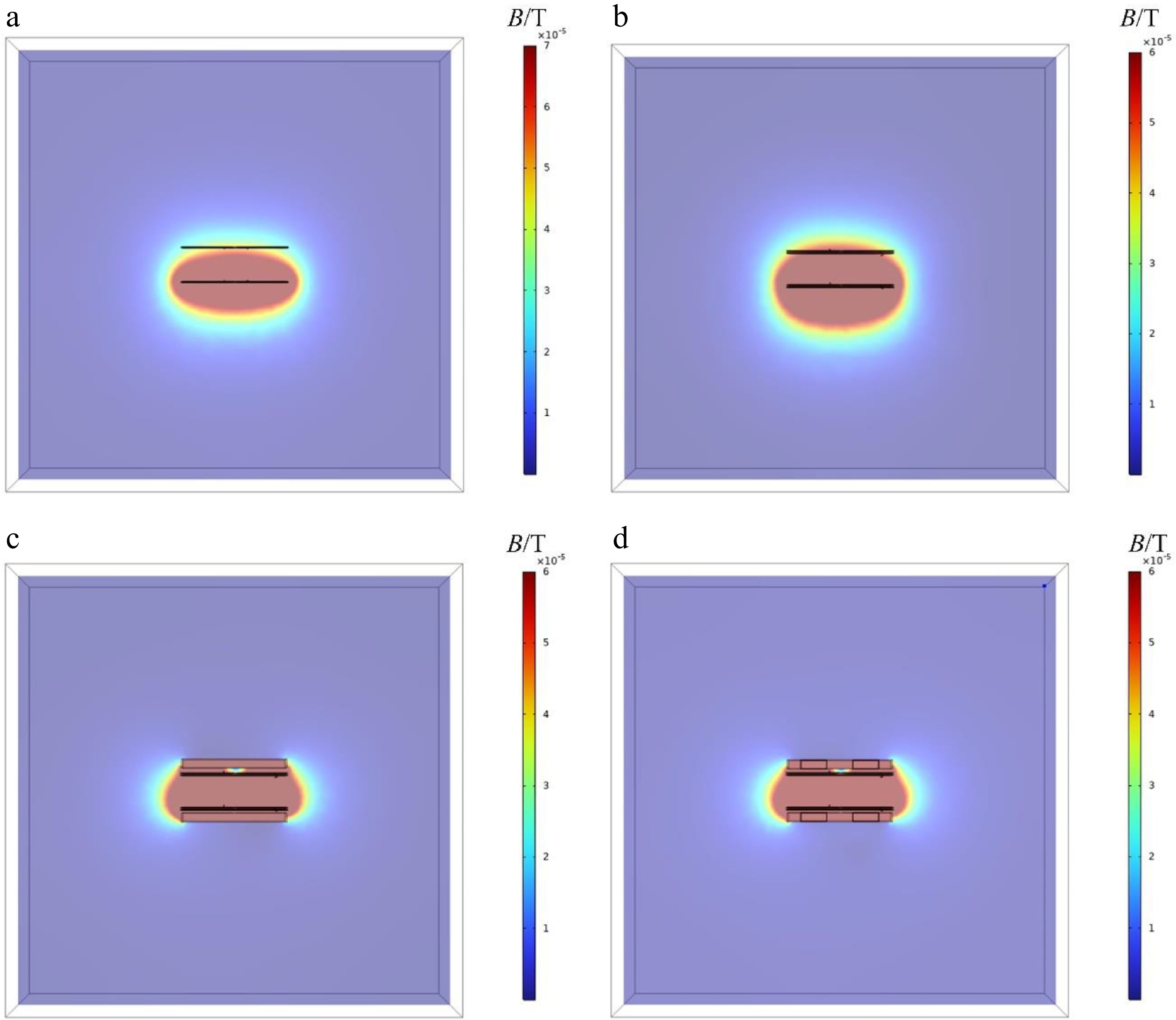
Figure 5.
Magnetic field contour plots of the XZ cross-section of the magnetic coupling mechanism under four scenarios. (a) Single DD magnetic coupling mechanism without magnetic core. DVDD magnetic coupling mechanism (b) without magnetic core, (c) with full-cover magnetic core, and (d) with new-type magnetic core.
As shown in Fig. 6, the 3D diagrams and front views of the mutual inductance variation for both the DVDD magnetic coupling mechanism and the single DD magnetic coupling mechanism are provided. These are for the case where no additional magnetic core is added, and when offsets occur in both X-axis and Y-axis direction. Figure 6 and b shows the mutual inductance variation for the DVDD magnetic coupling mechanism without a magnetic core when offsets occur in the X-axis and Y-axis direction. In the case where the magnetic coupling mechanism is aligned, the coil's equivalent mutual inductance is 5.2937 μH. After a 40 mm offset in the X-axis direction, the coil's equivalent mutual inductance is 3.2471 μH, showing a 38.66% change in mutual inductance. After a 40 mm offset in the Y-axis direction, the coil's equivalent mutual inductance is 1.990 μH, showing a 62.40% change in mutual inductance. When both X-axis and Y-axis direction experience a 40 mm offset, the equivalent mutual inductance becomes 0.254 μH, showing a 95.2% change in mutual inductance. Figure 6c and d shows the mutual inductance variation for the single DD magnetic coupling mechanism without a magnetic core when offsets occur in the X-axis and Y-axis direction. In the case where the magnetic coupling mechanism is aligned, the coil's equivalent mutual inductance is 3.3196 μH. After a 40 mm offset in the X-axis direction, the coil's equivalent mutual inductance is 0.17422 μH, showing a 94.75% change in mutual inductance. After a 40 mm offset in the Y-axis direction, the coil's equivalent mutual inductance is 2.6571 μH, showing a 19.95% change in mutual inductance. When both X-axis and Y-axis direction experience a 40 mm offset, the equivalent mutual inductance becomes 0.13229 μH, showing a 96.01% change in mutual inductance. The X-axis misalignment tolerance is significantly improved.
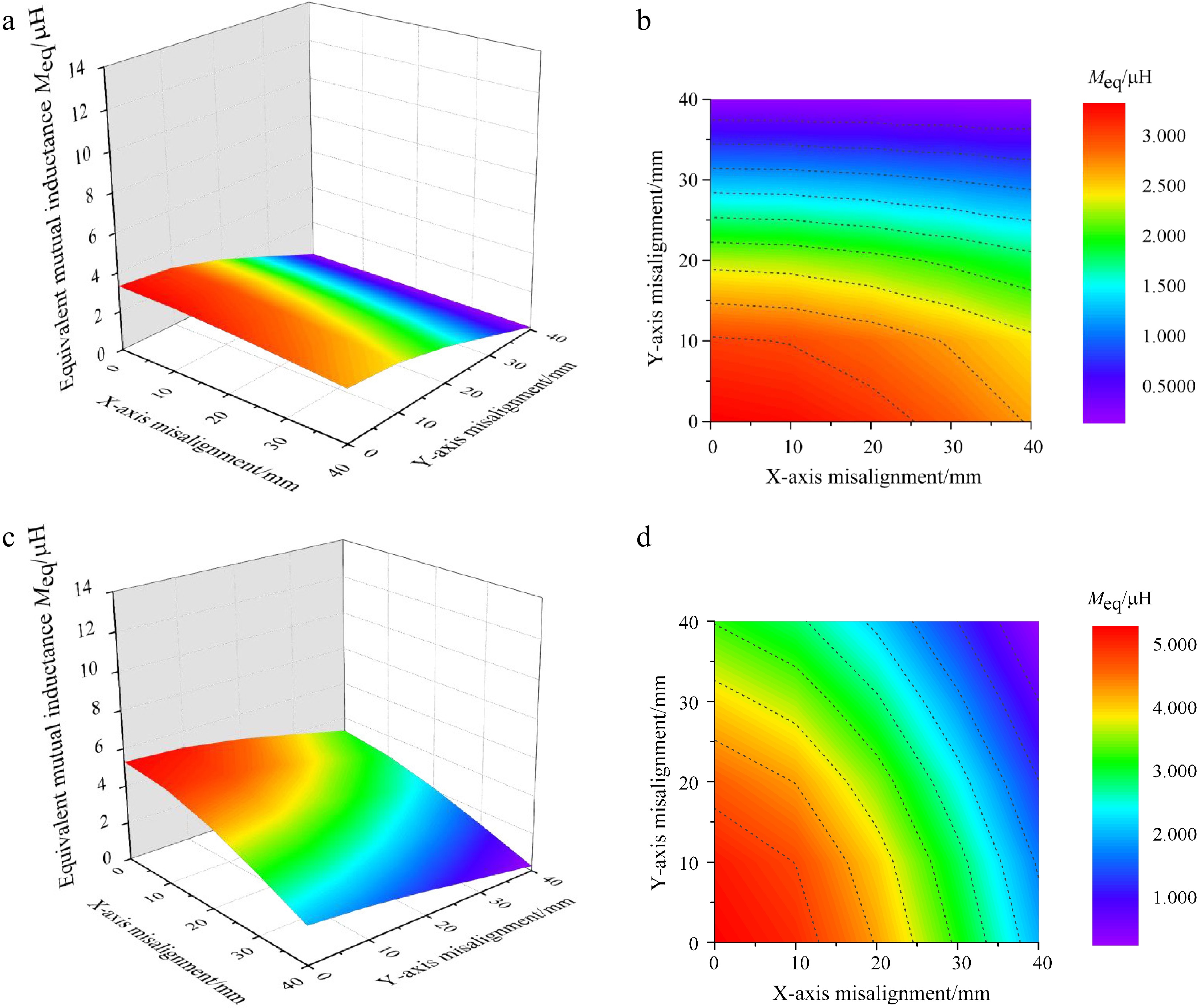
Figure 6.
Mutual inductance variation contour plots of two magnetic coupling mechanisms under misalignment conditions. (a) 3D diagram of the mutual inductance variation for single DD magnetic Coupling mechanism without magnetic core. (b) Front view of mutual inductance variation for single DD magnetic coupling mechanism without magnetic core. (c) 3D diagram of mutual inductance variation for DVDD magnetic coupling mechanism without magnetic core. (d) Front view of mutual inductance variation for DVDD magnetic coupling mechanism without magnetic core.
It can be concluded that the DVDD magnetic coupling mechanism, with two pairs of orthogonal coils, exhibits strong complementarity between the cross mutual inductances. This characteristic compensates for the lack of misalignment tolerance in X-axis direction for the single DD magnetic coupling mechanism, enabling the DVDD magnetic coupling mechanism to exhibit strong misalignment tolerance in both X-axis and Y-axis direction. Consequently, the DVDD magnetic coupling mechanism exhibits robust misalignment tolerance across the bidirectional (XY) plane, significantly broadening its feasible deployment domains in practical wireless power transfer systems.
As shown in Fig. 7, the 3D diagrams and 3D front views present the variation of the equivalent mutual inductance when the DVDD magnetic coupling mechanism experiences shifts in the X-axis and Y-axis direction, in both the full-cover magnetic core and the new-type magnetic core configurations. Figure 7a and b illustrates the mutual inductance variation for the DVDD magnetic coupling mechanism with a full-cover magnetic core. In the aligned state of the coupling mechanism, the coil's equivalent mutual inductance is 13.862 μH. When a 40 mm shift occurs only in the X-axis direction, the coil's equivalent mutual inductance becomes 9.1620 μH, showing a 33.91% change. When a 40 mm shift occurs only in the Y-axis direction, the coil's equivalent mutual inductance is 6.0455 μH, with a 56.38% change. When both X-axis and Y-axis direction experience a 40 mm shift, the equivalent mutual inductance is 1.6087μH, with an 88.25% change. Figure 7c and d demonstrates the mutual inductance variation of the DVDD magnetic coupling mechanism with a new-type magnetic core. In the aligned state of the coupling mechanism, the coil's equivalent mutual inductance is 13.115 μH. When a 40 mm shift occurs only in the X-axis direction, the coil's equivalent mutual inductance is 8.6893 μH, showing a 33.74% change. When a 40 mm shift occurs only in the Y-axis direction, the coil's equivalent mutual inductance becomes 5.7433 μH, with a 56.20% change. When both X-axis and Y-axis direction experience a 40 mm shift, the equivalent mutual inductance is 1.4919 μH, showing an 88.6% change.
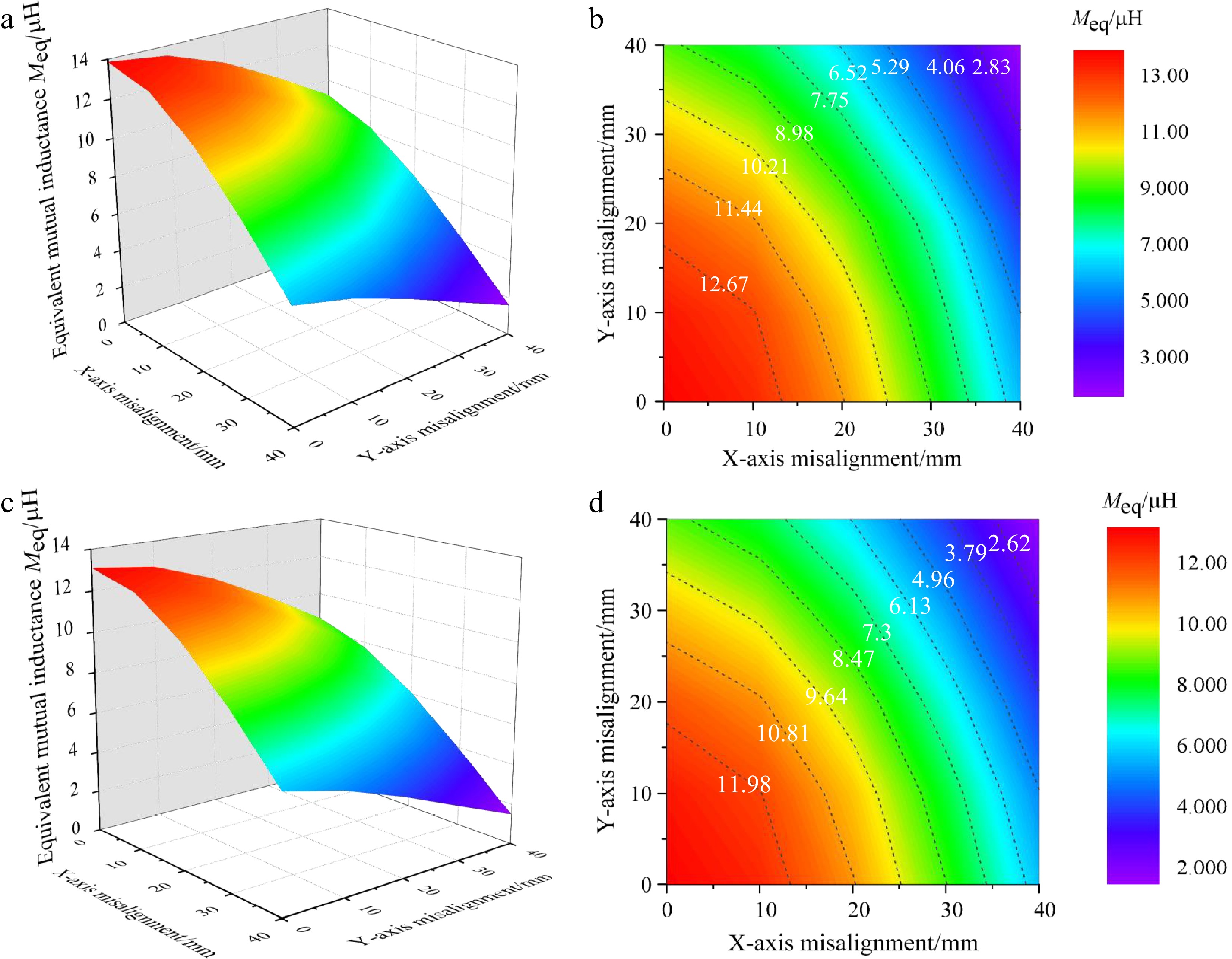
Figure 7.
Mutual inductance variation contour plots of two magnetic cores under misalignment conditions. (a) 3D diagram of the mutual inductance variation for DVDD magnetic coupling mechanism with full-coverage magnetic core. (b) Front view of the mutual inductance variation for DVDD magnetic coupling mechanism with full-coverage magnetic core. (c) 3D view of mutual inductance variation for DVDD magnetic coupling mechanism with new-style magnetic core. (d) 3D diagram of mutual inductance variation for DVDD magnetic coupling mechanism with new-type magnetic core.
Based on the above results, the new-type magnetic core structure reduces the magnetic core usage by 26.6% compared to the full-cover magnetic core structure, while maintaining the magnetic coupling strength and misalignment tolerance. This contributes to the lightweight design of the magnetic core and a reduction in costs.
As shown in Fig. 8, the CCRR variation in both X-axis and Y-axis direction for the single DD magnetic coupling system without a magnetic core, and the DVDD magnetic coupling system with no magnetic core, full-cover magnetic core, and new-type magnetic core, is presented. In the analysis, the coil dimensions, number of turns, and coupling spacing for both the single DD magnetic coupling system and the DVDD magnetic coupling system are the same. As illustrated, in the absence of a magnetic core, the CCRR contour lines for the single DD magnetic coupling system are nearly parallel to the Y-axis, indicating that the offset in the X-axis direction significantly affects the coupling coefficient, and there is no misalignment tolerance in X-axis direction. In contrast, the DVDD magnetic coupling system shows a more balanced misalignment tolerance in both X-axis and Y-axis directions. This further proves that the DVDD magnetic coupling system compensates for the lack of misalignment tolerance in X-axis direction for the single DD magnetic coupling system, making it suitable for a broader range of applications. Additionally, in the absence of a magnetic core, the area where the CCRR contour lines for the DVDD magnetic coupling system are greater than or equal to 0.3 is 1.14 times larger than that for the single DD magnetic coupling system, indicating a 14.5% improvement in the coupling coefficient retention ratio. This suggests that the overall misalignment tolerance of the DVDD magnetic coupling system is superior to that of the single DD magnetic coupling system.
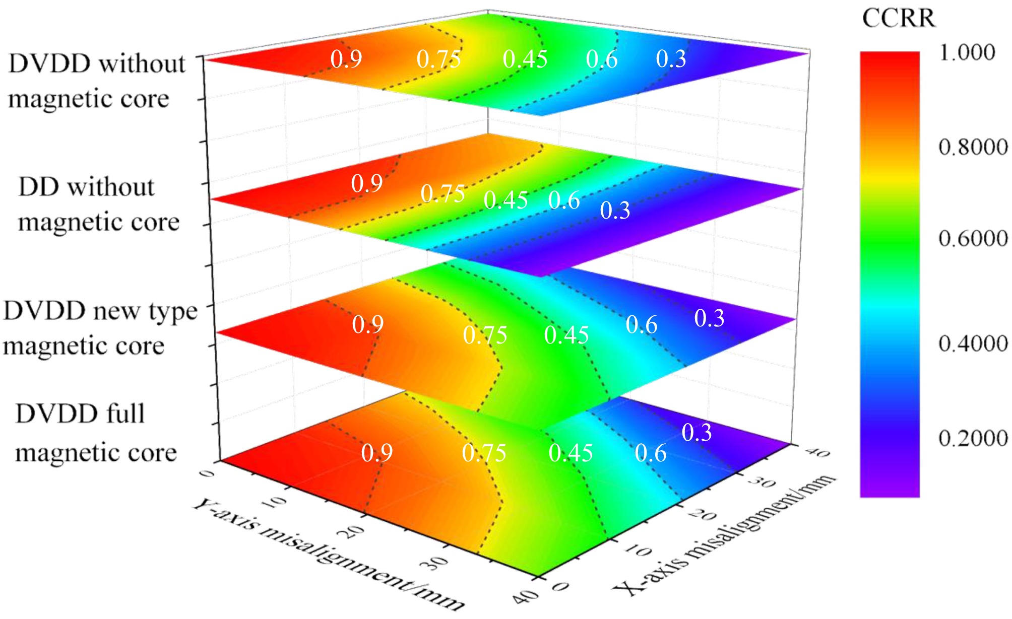
Figure 8.
Impact of X/Y misalignment on CCRR in four cases.
The CCRR contour distributions for the DVDD magnetic coupling system with both full-cover and new-type magnetic cores are nearly identical. In the case of the full-cover magnetic core, the area where the CCRR contour lines for the DVDD magnetic coupling system are greater than or equal to 0.3 is 1.002 times larger than that for the new-type magnetic core, showing a 0.2% decrease in the coupling coefficient retention ratio. This indicates that the misalignment tolerance of the DVDD magnetic coupling systems with the full-cover and new-type magnetic cores is almost identical. This further demonstrates that the novel magnetic core maintains equivalent misalignment tolerance while reducing core material usage by 26.6%.
In summary, the comparison shows that the DVDD magnetic coupling system has strong misalignment tolerance in both X-axis and Y-axis direction, compensating for the lack of misalignment tolerance in X-axis direction of the single DD coil magnetic coupling system. At the same time, its overall misalignment tolerance is superior to that of the single DD coil magnetic coupling system. The DVDD magnetic coupling system, with the new-type magnetic core, while reducing the magnetic core usage by 26.6%, still maintains a coupling strength and misalignment tolerance comparable to the full-cover magnetic core. Compared with the DD[24] and DDQ[25] magnetic coupling mechanisms, the DVDD magnetic coupling mechanism demonstrates enhanced capability in maintaining the magnetic coupling coefficient, achieving a CCRR of 93% at 15% misalignment. This performance surpasses the 90.9% CCRR of the DD configuration and the 87% CCRR of the DDQ configuration under equivalent misalignment conditions.
Experimental verification
-
Based on the size parameters of the DVDD magnetic coupling mechanism given in Table 1, the DVDD coil was fabricated using Litz wire of different specifications, tightly wound onto a 2 mm thick 3D-printed resin groove board. The completed DVDD coil to be tested is shown in Fig. 9. An inductance parameter testing experimental platform was also set up, as shown in Fig. 10, where the impedance analyzer used is the Agilent 4294A, and the test fixture is the 16047E.
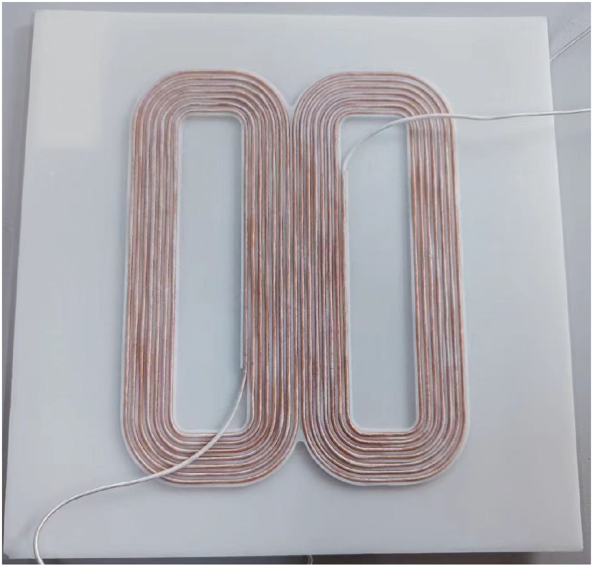
Figure 9.
Physical schematic of the DVDD coil.
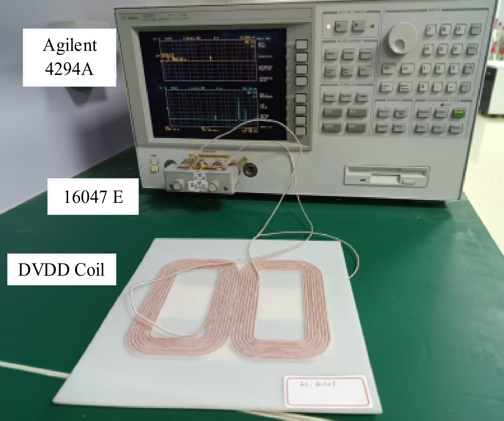
Figure 10.
DVDD coil inductance parameter testing platform.
The resonant capacitance required for the WPT system was calculated based on the measured self-inductance data of the primary-side and secondary-side coils, in conjunction with Eqs (17)–(19). In these equations, f denotes the system operating frequency, L1 represents the compensation inductance, LP and LS correspond to the self-inductances of the transmitting and receiving coils, respectively. In the LCC-S resonant compensation network, C1, C2, and C3 denote the compensation capacitors. The derived key circuit parameters of the system are summarized in Table 2.
Table 2. Main circuit parameters of the wireless power transfer system.
Parameters Values Parameters Values L1 2.2 μH C1 1.15 μF LS 47.586 μH C2 51.88 nF LP 50.866 μH C3 53.285 nF Udc 7 V f 100 kHz RL 20 Ω $ {C}_{1}=\dfrac{1}{{(2{\text π} f)}^{2}\cdot {L}_{1}} $ (17) $ {C}_{2}=\dfrac{1}{{(2{\text π} f)}^{2}\cdot({L}_{\text{P}}-{L}_{\text{1}})} $ (18) $ {C}_{3}=\dfrac{1}{{(2{\text π} f)}^{2}\cdot{L}_{\text{S}}} $ (19) Based on the coil data of the DVDD magnetic coupling mechanism in Table 1 and the system's main circuit parameters in Table 2, an experimental prototype was built to verify the misalignment tolerance of the DVDD magnetic coupling mechanism in both X-axis and Y-axis direction.
The experimental prototype of the WPT system using the DVDD magnetic coupling mechanism is shown in Fig. 11. The labels in the figure correspond to the following components: ① DC power supply; ② Primary circuit of the wireless power transfer system; ③ Primary coil of the DVDD magnetic coupling mechanism; ④ Secondary coil of the DVDD magnetic coupling mechanism; ⑤ Secondary circuit of the wireless power transfer system; ⑥ Oscilloscope (Model: RTB 2004). In this setup, both the transmitting and receiving coils of the DVDD magnetic coupling mechanism are wound with 0.1 mm × 120 strands of Litz wire, with each D-shaped coil consisting of eight turns. The coil magnetic core uses PC95-type power ferrite material.
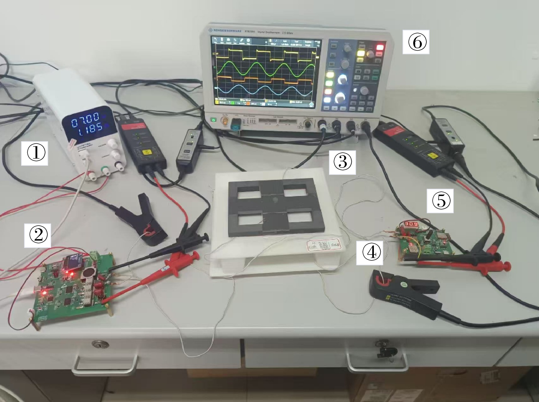
Figure 11.
Experimental platform of the WPT system based on the DVDD magnetic coupling mechanism
To verify the offset resistance characteristics of the DVDD magnetic coupling mechanism in both X-axis and Y-axis direction, the corresponding equivalent inductance is measured and calculated at different positions, with the reference position being the aligned position with a 40 mm gap. The equivalent mutual inductance of the DVDD magnetic coupling mechanism when offset in both X-axis and Y-axis direction is shown in Fig. 12. Additionally, to validate the transmission characteristics of the WPT system with the DVDD magnetic coupling mechanism under offset conditions, the experimental waveforms of the output voltage of the inverter U1, the rectifier's equivalent AC voltage U2, the transmitter coil current IP, and the receiver coil current IS are shown in Fig. 13.
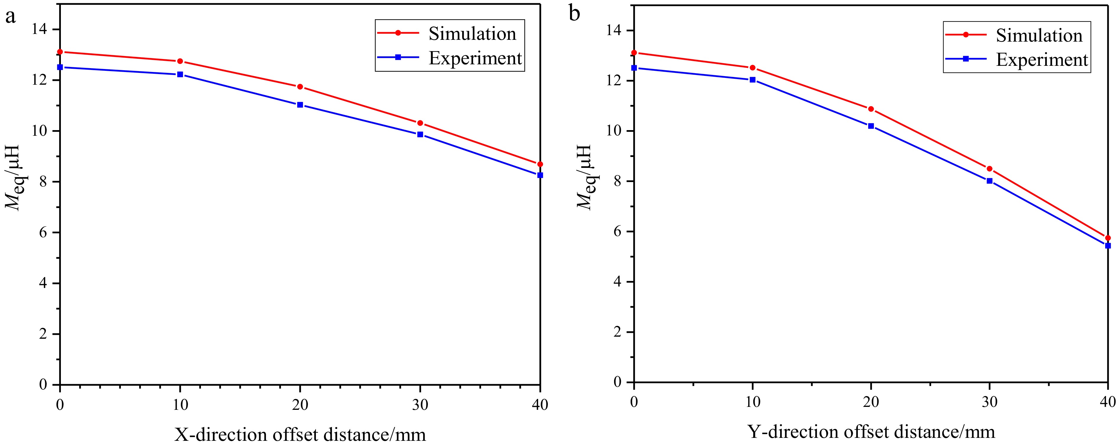
Figure 12.
Mutual inductance variation curve of DVDD magnetic coupling mechanism under X-axis and Y-axis direction misalignment. Mutual inductance change curve under (a) X-axis direction misalignment and (b) Y-axis direction misalignment.
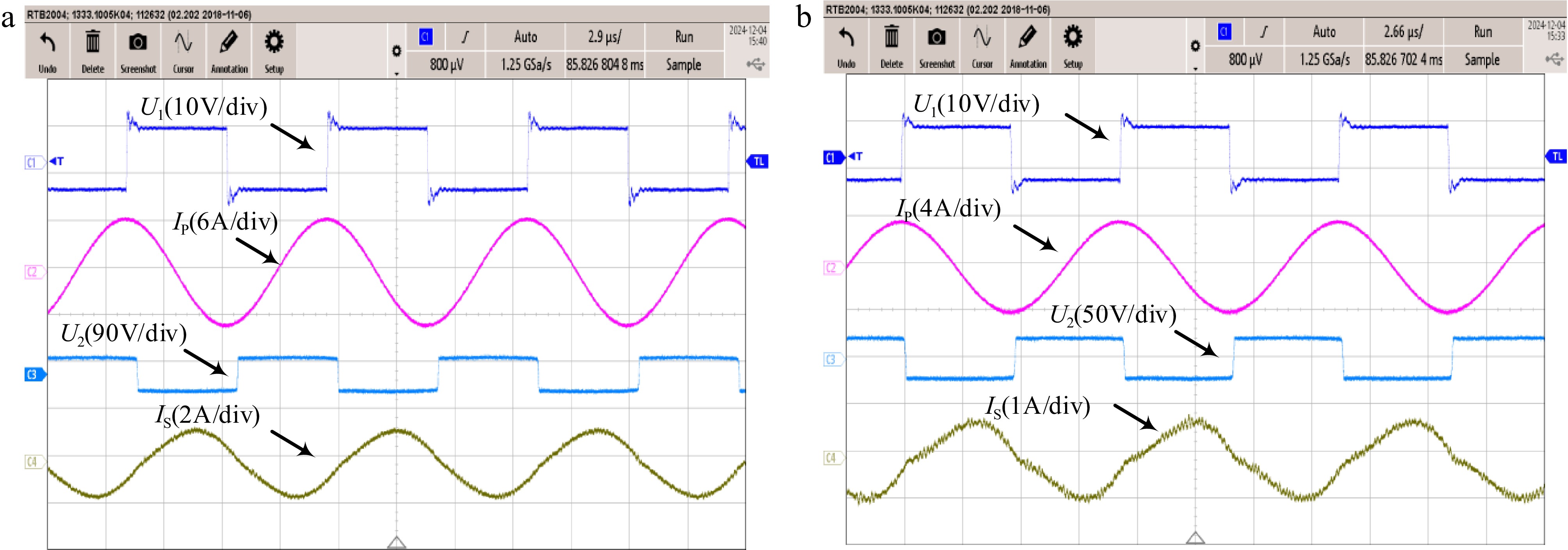
Figure 13.
Experimental waveforms. Waveform diagram under (a) magnetic coupling alignment and (b) 4 cm misalignment of magnetic coupling mechanism.
The equivalent mutual inductance measurement results of the DVDD system are shown in Fig. 12. Under X-axis misalignment, experimental measurements and analytical calculations demonstrate close agreement with COMSOL Multiphysics finite element simulations. This experimentally confirms the theoretical validity of misalignment tolerance in the DVDD magnetic coupling mechanism. The waveform of the WPT system is shown in Fig. 13. In both the aligned and 4 cm misalignment cases, the phase difference between the output voltage of the inverter U1 and the transmitter coil current IP remains at 90°, satisfying the resonant excitation requirements of the DVDD coupling mechanism.
-
This paper presents a novel DVDD magnetic coupling mechanism, which has the advantages of a lightweight core structure and strong misalignment tolerance. The DVDD magnetic coupling mechanism achieves these advantages by adopting two vertically stacked and orthogonally placed double DD coils, along with a lightweight, partially covered magnetic core structure. Simulation results show that in the case of no magnetic core, the area corresponding to the magnetic coupling coefficient retention rate of the DVDD magnetic coupling mechanism with a retention rate of no less than 0.3 is 1.14 times that of the single DD magnetic coupling mechanism, representing a 14.5% increase in the coupling coefficient retention rate. This indicates that the overall misalignment tolerance of the DVDD magnetic coupling mechanism is superior to that of the single DD magnetic coupling mechanism. Furthermore, for the DVDD magnetic coupling mechanism, the effective area where the coupling coefficient retention rate remains no less than 0.3 with the full-cover magnetic core is 1.002 times that of the proposed partially-covered magnetic core. This marginal 0.2% CCRR reduction confirms that the novel partially-covered design achieves equivalent magnetic coupling performance and comparable misalignment tolerance while reducing magnetic core material consumption by 26.6%. Comparative experiments demonstrate that under 15% misalignment, the DVDD mechanism achieves a CCRR of 93%. This performance exceeds the 90.9% CCRR of the DD configuration and the 87% CCRR of the DDQ configuration under equivalent misalignment conditions. Finally, a WPT system experimental prototype using the DVDD magnetic coupling mechanism was developed, and the equivalent mutual inductance under both alignment and misalignment conditions was measured and compared with simulation results.
-
The results indicate that the proposed DVDD magnetic coupling mechanism effectively achieves misalignment tolerance in multiple directions, while also reducing the use of magnetic core material and associated costs.
Special thanks to the Natural Science Basic Research Program of Shaanxi Province Program (Grant No. 2024JC-YBMS-346), the Shaanxi Provincial Technology Innovation Guidance Fund Household Photovoltaic-Storage Integrated Controller Project (2025ZC-YYDP-23) for providing the necessary resources and financial support, which made this study possible.
-
The authors confirm contribution to the paper as follows: study conception and design: Wan X, Jiang J, Liu B; data collection: Wan X, Jiang J; analysis and interpretation of results: Wan X, Jiang J; draft manuscript preparation: Wan X, Jiang J. All authors reviewed the results and approved the final version of the manuscript.
-
The data that support the findings of this study are available upon request from the corresponding author.
-
The authors declare that they have no conflict of interest.
- Copyright: © 2025 by the author(s). Published by Maximum Academic Press, Fayetteville, GA. This article is an open access article distributed under Creative Commons Attribution License (CC BY 4.0), visit https://creativecommons.org/licenses/by/4.0/.
-
About this article
Cite this article
Wan X, Jiang J, Liu B. 2025. Optimization study on misalignment tolerance of a wireless power transfer system with double-layer vertical DD coils. Wireless Power Transfer 12: e025 doi: 10.48130/wpt-0025-0022 

Optimization study on misalignment tolerance of a wireless power transfer system with double-layer vertical DD coils
- Received: 28 February 2025
- Revised: 21 May 2025
- Accepted: 26 June 2025
- Published online: 29 September 2025
Abstract: To address the issue of coil misalignment in magnetically coupled wireless power transfer (WPT) systems, which causes fluctuations in mutual inductance, a reduction in the magnetic coupling coefficient, and a decline in transmission efficiency, this paper proposes a misalignment tolerance WPT system. The system utilizes a novel dual-layer vertical DD (DVDD) coil coupling mechanism, featuring an innovative magnetic core design. A mathematical model of the DVDD mechanism has been developed and analyzed to characterize its output properties. Comparative evaluation of equivalent mutual inductance variation and coupling coefficient retention demonstrates the DVDD's superiority over conventional magnetic coupling mechanisms. The DVDD mechanism achieves a 14.5% improvement in coupling coefficient retention compared to traditional DD magnetic coupling mechanisms. Furthermore, the newly designed magnetic core achieves 26.6% material reduction relative to conventional full-coverage designs while preserving 98% of the magnetic coupling coefficient retention rate in the full-coverage magnetic core. These combined improvements ensure enhanced operational stability in dynamic WPT systems. A WPT system prototype implementing the DVDD magnetic coupling mechanism was developed. Experimental and simulation results demonstrated close agreement, confirming the enhanced misalignment tolerance of the DVDD mechanism and the feasibility of the lighter magnetic core design.