


-
With the swift progression of electronic technology, smartphones, smart homes, electric vehicles, and other electronic devices have seamlessly integrated into our daily lives, yet the necessity for frequent charging has grown increasingly prominent[1−4]. Traditional wired power transmission encounters numerous challenges that hinder its efficiency and reliability, such as harsh transmission environments and significant construction and maintenance costs[5−8]. Wireless power transfer (WPT) provides a more convenient and secure energy replenishment method for these devices[9−14].
The series-series (S-S) compensated WPT system is favored for its constant-current output and load-independent frequency characteristics. Furthermore, it demonstrates exceptional near-field power transmission performance, making it ideal for high-efficiency short-distance power delivery[15,16]. However, the primary current exhibits an inverse relationship with the coupling coefficient. Consequently, under a physical separation or no-load conditions, the primary current surges significantly. Such a surge risks damaging the power supply and poses safety hazards to the system[17,18]. To address no-load overcurrent, improved compensation networks (e.g., LCC-LCC, LCC-S) have been developed, where primary current scales with coupling coefficient[19,20]. While effective at lower frequencies, their MHz-range application is limited by high-frequency losses. An alternative RF power supply using a bidirectional coupler and capacitor-array matching network enables communication-free impedance control[21], though added integrated circuits reduce system efficiency. The parallel-parallel (P-P) compensated WPT system effectively mitigates the safety risks associated with S-S compensation under no-load conditions, owing to the high-impedance characteristics of its parallel resonance point[22]. However, the P-P compensated topology exhibits a notable drawback: its resonant frequency is influenced by both the coupling coefficient and load conditions. This dual dependency results in degraded power transfer stability and high sensitivity to load variations, thereby severely restricting the practical application scope of this topology[23]. Therefore, effectively integrating the advantages of S-S and P-P compensation topologies to develop WPT systems with high efficiency, broad applicability, and enhanced safety constitutes a key technical challenge in the current wireless power transfer field.
In this paper, a novel coupling structure is proposed where both sides of the structure are connected by planar alternative-winding coils (PAWC) combined with magnetic backplates. The influence of variations in the positional relationship between magnetic materials and coils on their operating frequency, as well as the impact of frequency offsets on the impedance of PAWC. The PAWC operates at a high-impedance state resembling parallel resonance characteristics when only the transmitting coil is active (no-load condition). In this state, no current flows through the transmitter, and no power output is generated, which is equivalent to an open-circuit state, thereby completely eliminating the safety hazards caused by the excessive current in S-S-compensated systems during no-load operation. When the system enters charging mode, the receiver's magnetic backplate and coil move closer to the transmitter, shifting the operating frequency to an optimal state where the impedance's imaginary part reaches zero. The switching between operational states is achieved solely through changes in the relative physical positions of the coils, requiring no additional control devices. It is noteworthy that current mainstream wireless charging applications (such as mobile phone charging) inherently require the receiver to be in close proximity to the transmitter. Therefore, in daily use, this design only requires conventional placement/removal operations to automatically complete state switching, perfectly matching user habits.
Compared with traditional solutions, when PAWC is not working under no-load conditions, the transmitter exhibits a high-impedance state, defined in this paper as the open-circuit frequency (OCF), where no current flows. When placing the receiver in the charging position during charging, PAWC demonstrates an impedance with zero imaginary part at the same operating frequency, defined as the short-circuit frequency (SCF) point. In this state, high-efficiency transmission is achieved without requiring compensation networks while also featuring significant advantages, including constant current output, wide-range high-efficiency energy transmission, and load-independent resonant frequency characteristics, demonstrating broad application prospects.
-
This section examines the influence of magnetic materials on coil resonant frequency, analyzing the characteristics of S-S compensated coils with magnetic backplates under both operating and no-load conditions. Based on the impedance characteristics of AWC, a design scheme is proposed to achieve automatic switching between OCF and SCF states through magnetic material-induced frequency shifting.
Effect of magnetic materials on the resonant frequency
-
When the spatial position of the magnetic material relative to the coil changes, it leads to a variation in the spatial permeability around the coil. The relationship between the spatial permeability and the coil inductance is as follows[24]:
$ L=\mu N^2\left[\ln(\dfrac{8r}{a})-1.75\right] $ (1) where, N, r, and a represent the number of coil turns, wire radius, and wire constant respectively, which are only related to the wire itself. When the position of the magnetic material relative to the coil changes, it leads to a variation in the spatial permeability μ.
From Eq. (1), it can be seen that when the relative permeability of the space changes, it will result in a change in the coil's self-inductance L.
$ {\omega _0} = \dfrac{1}{{\sqrt {LC} }} $ (2) In Eq. (2), it can be seen that when the inductance L changes, it leads to an offset in the resonant frequency, and ultimately, at the same frequency as the position of the magnetic material changes, it leads to a change in the impedance of the coil.
Effect of frequency offset on S-S compensation coil
-
In the study of WPT, most coupling coils use S-S compensation coils due to their simple structure and resonant frequency independence from the coupling coefficient and load. Figure 1a shows the equivalent circuit diagram of the S-S compensation coil system. In this diagram, Uin serves as the voltage source, with Ct and Cr representing the compensation capacitors at the transmitting (TX) and receiving (RX) ends, respectively. Lt and Rt are the inductance and internal resistance of the TX coil, while Lr and Rr are the inductance and internal resistance of the RX coil. RL is the load of the system. The input impedance of this system can be expressed as:
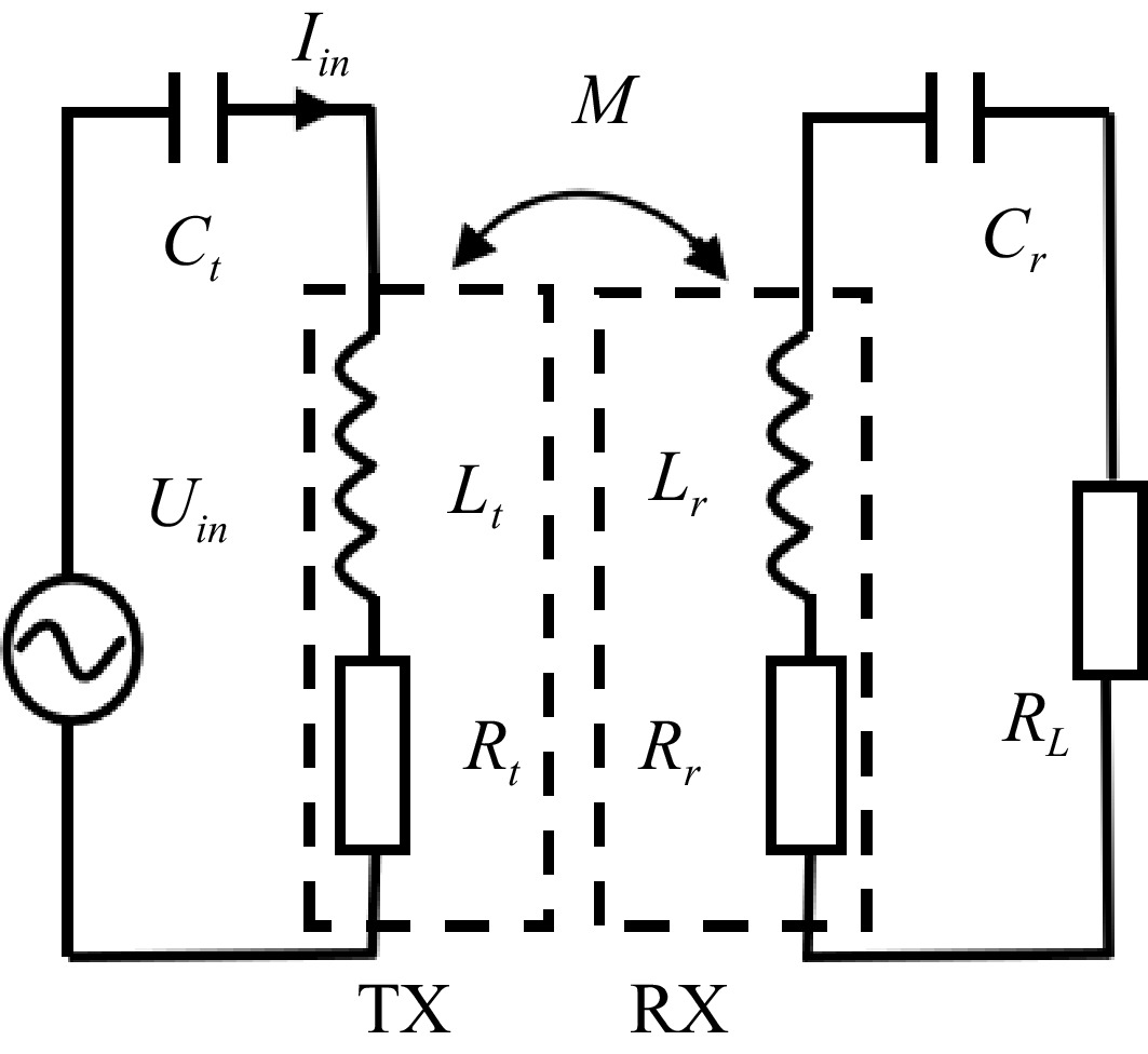
Figure 1.
Equivalent circuit diagram of S-S compensated coil system.
$ {Z_{{\text{in}}}} = jX + {R_t} + {Z_{rf}} $ (3) where the reflected impedance Zrf is given by:
$ {Z_{rf}} = \dfrac{{{\omega ^2}{M^2}}}{{\dfrac{1}{{j\omega {C_r}}} + j\omega {L_r} + {R_L} + {R_r}}} $ (4) where, M represents the mutual inductance between the two coils. The current value at the input end of the coil system is as follows:
$ {I_{in}} = \dfrac{{{U_{in}}}}{{{Z_{in}}}} = \dfrac{{{U_{in}}}}{{jX + {R_t} + {Z_{rf}}}} $ (5) To further investigate the impact of magnetic backplate on the resonance frequency shift of the coil, as well as analyze the current characteristics of the S-S compensated coil with integrated magnetic backplate under both working and no-load conditions, an S-S compensated coil structure distributed on both sides of a dielectric plate was designed, with its diagram shown in Fig. 2a. With the magnetic backplate integrated into this structure, a resonance at 13.56 MHz was successfully achieved. Figure 2b presents the frequency response characteristics of coil input impedance during operation, demonstrating that when the system reaches its operating point with zero imaginary impedance, the input current achieves optimal performance for highly efficient power transfer. The corresponding transmitter-side voltage and current waveforms under these conditions are illustrated in Fig. 3.
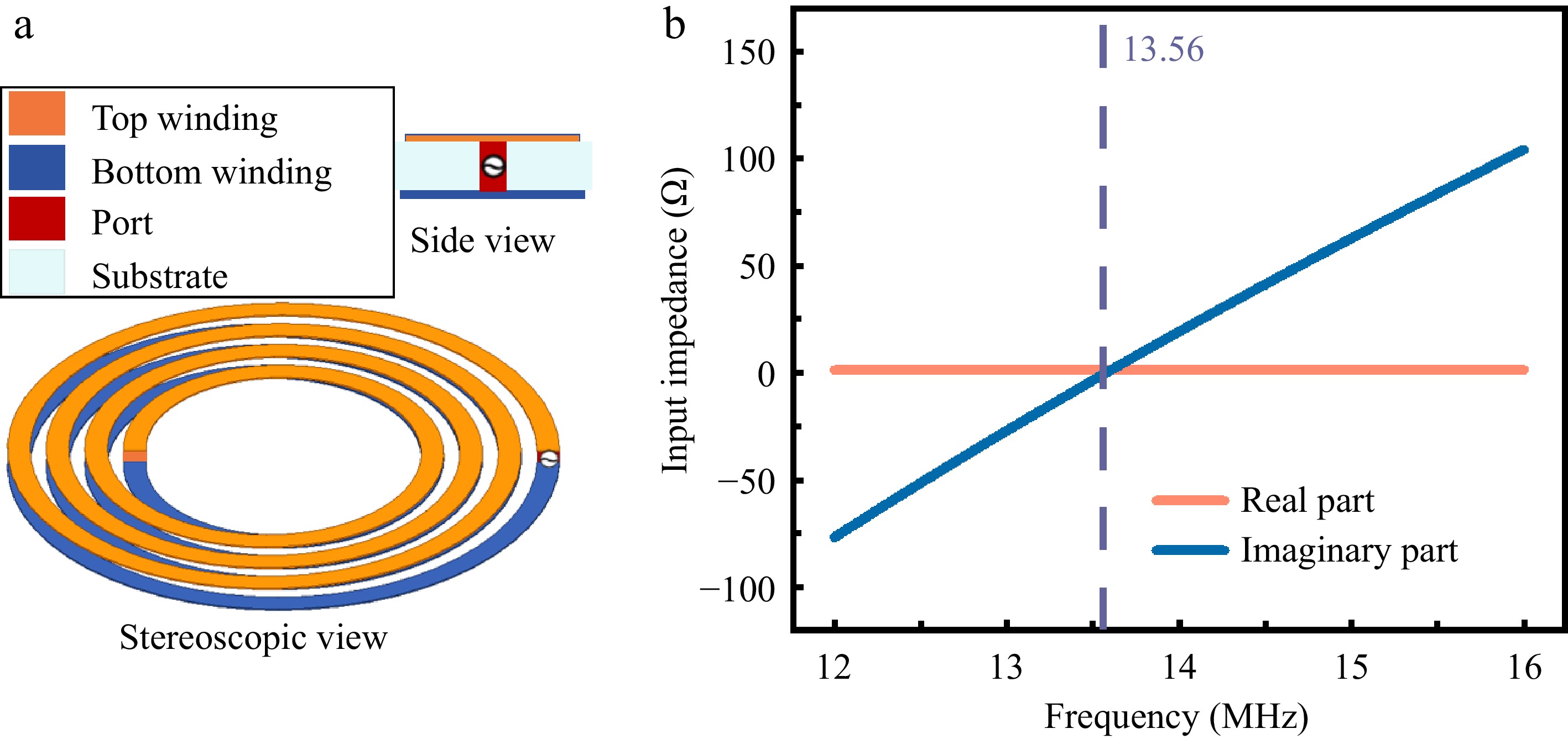
Figure 2.
(a) Structural characteristics of dielectric-substrate-bilateral S-S compensation. (b) Frequency-dependent input impedance characteristics.
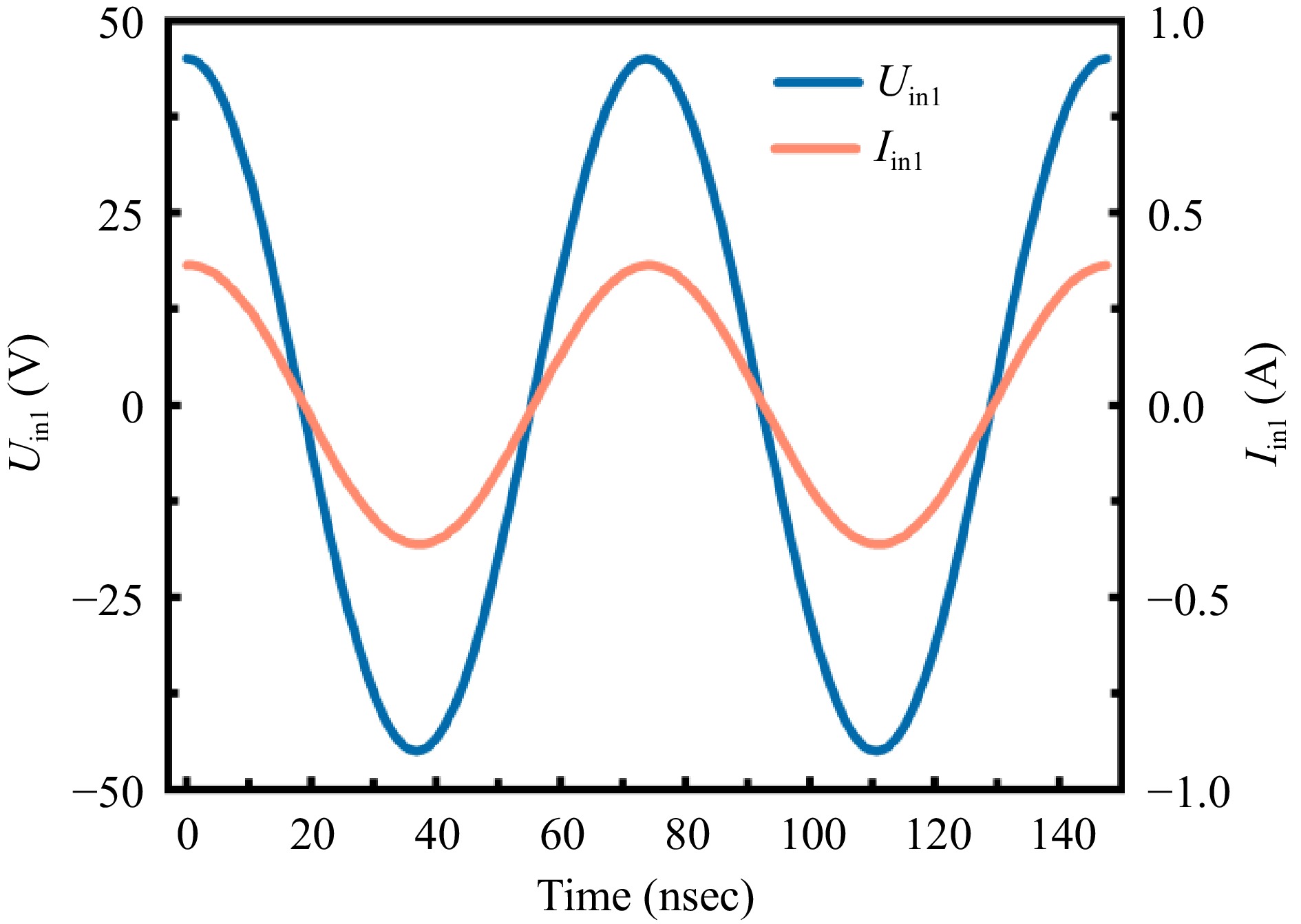
Figure 3.
Voltage and current waveforms at the transmitter side of the S-S compensated coil under operating conditions.
When the receiver moves away from the system under no-load conditions, the equivalent circuit model is shown in Fig. 4a. The removal of the receiver's magnetic backplate reduces the effective permeability of the surrounding medium, consequently increasing the transmitter coil's resonant frequency and altering its impedance characteristics, as clearly demonstrated in Fig. 4b. In this decoupled state, the mutual inductance M decreases to zero and the reflected impedance from the receiver side vanishes, with the system's current behavior being described by:
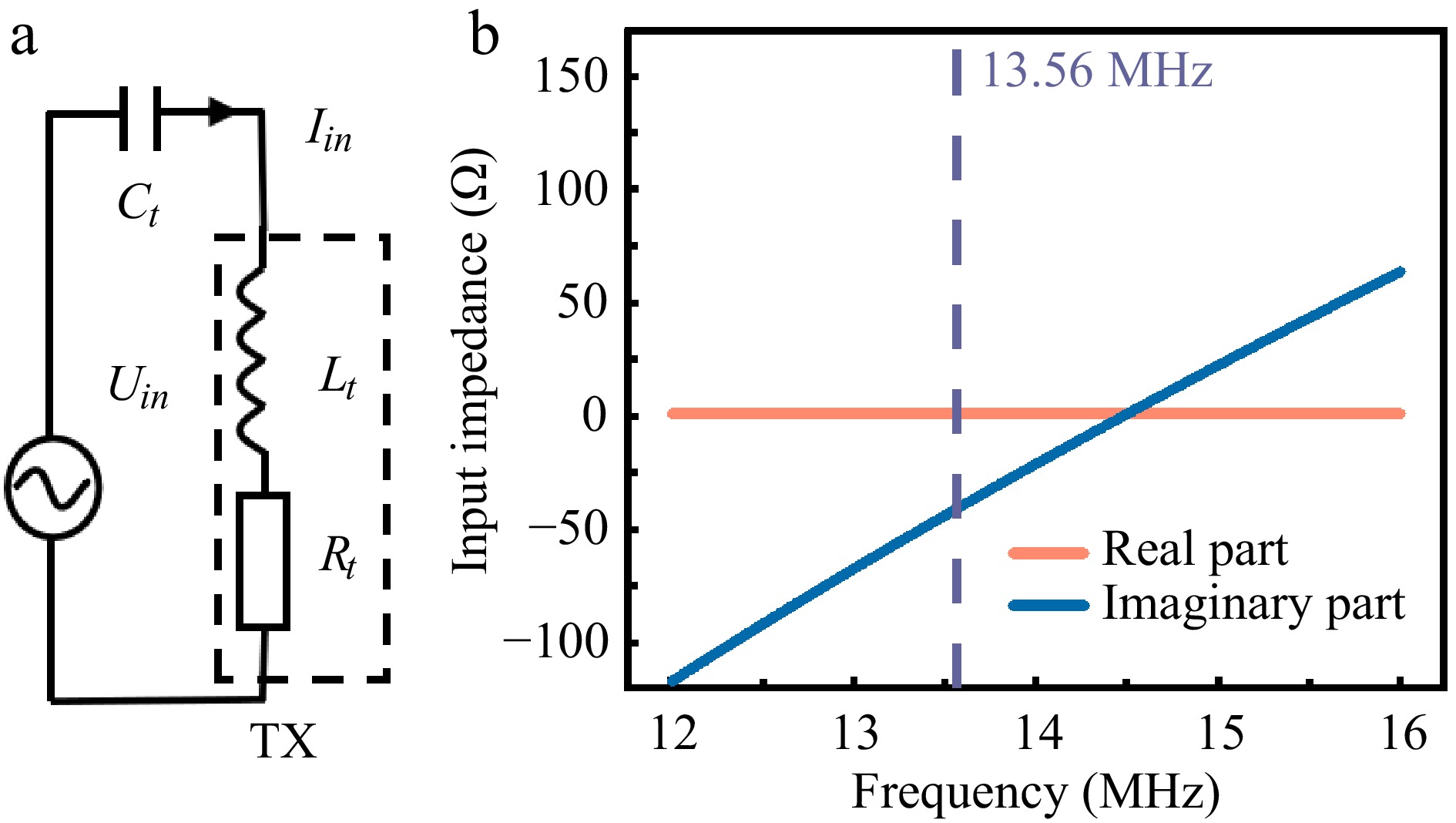
Figure 4.
(a) Equivalent circuit diagram of the S-S compensated coils under no-load condition. (b) Functional relationship between input impedance and frequency.
$ {I_{in}} = \dfrac{{{U_{in}}}}{{j{X_{}} + {R_t}}} $ (6) However, this S-S compensated coil configuration exhibits negligible impedance variation during frequency shifting, with merely several tens of ohms fluctuation in the imaginary component-insufficient to reduce the no-load input current Iin to zero.
As demonstrated in Fig. 5, the transmitter maintains substantial voltage and current amplitudes under no-load conditions. The persistently high current flow, without energy dissipation through receiver-side loading, creates critical system safety hazards. To ensure the safety of the transmitter under no-load conditions, it is essential to maintain sufficiently high coil impedance. When the equivalent impedance jX + Rt in Eq. (6) reaches a sufficiently large magnitude, the transmitter current Iin becomes negligible. Therefore, a novel coil design featuring near-infinite impedance characteristics under no-load conditions is required to fundamentally address current-related safety concerns.
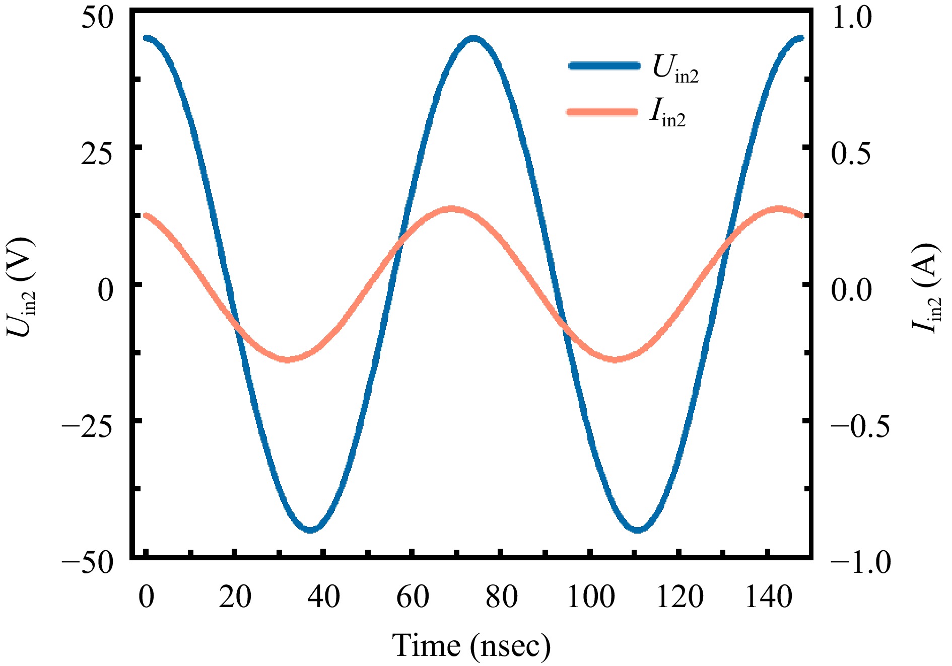
Figure 5.
Voltage and current waveforms at the transmitter side of the S-S compensated coil under no-load conditions.
Frequency-impedance characteristics of AWC
-
The AWC structure is characterized by its unique winding configuration where the central segment is wound in the opposite direction to the end segments, with the three sections maintaining a precise 1:2:1 turns ratio. The structure achieves self-resonance without requiring a compensation network and outperforms conventional coils[25]. In addition to AWC's superior performance, the impedance vs frequency characteristic is crucial. As shown in Fig. 6, when the system contains only the receiver in no-load condition, the coil is designed to operate at the frequency point where the impedance magnitude approaches infinity − this characteristic frequency is formally defined as the OCF. Under OCF operation mode, the input impedance Zin approaches infinity, driving the system current Iin to asymptotically approach zero, thereby completely eliminating the overcurrent risk inherent in S-S compensated coils during no-load conditions. Importantly, a corresponding characteristic frequency point exists in the adjacent frequency domain where the impedance imaginary part becomes zero, defined as the SCF. When the system operates at SCF, the imaginary impedance components at both coil terminals vanish simultaneously, enabling optimal power transfer efficiency without additional compensation networks. Therefore, at the OCF of the AWC, an impedance close to infinity can be achieved. Meanwhile, within a closely adjacent frequency range, there is an SCF point that can be utilized for energy transfer through the coil.
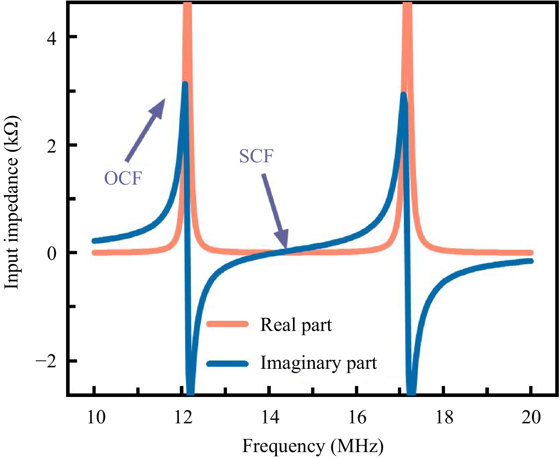
Figure 6.
Frequency-dependent input impedance characteristics of AWC.
Combined with the effect of the magnetic material on the resonant frequency of the coil, it can be envisioned that when only the TX coil is energized, the OCF is aligned with the operating frequency of 13.56 MHz. At this frequency, the coil impedance approaches infinity under no-load conditions. Placing the RX coil in the charging position causes the magnetic backplates to approach each other. This results in an increase in the spatial permeability and, consequently, an increase in the coil's self-inductance, leading to a decrease in frequency. The entire impedance curve shifts to the left, causing the first OCF point to move leftward to approximately 12 MHz. However, our primary focus at this stage is on the SCF point at the operating frequency of 13.56 MHz. This achieves the switching between the first OCF and SCF at 13.56 MHz. The first OCF point was selected because the entire impedance curve shifts leftward during the charging process. Only when the SCF is positioned on the right side can it be shifted to 13.56 MHz.
Design of the coupling structure
-
This section is the design of the coupling structure and its simulation, which includes the planarization design of the AWC coil and the selection of the magnetic backplate. The switching between two states of extremely high-impedance and operational states at a single operating frequency. Based on the analysis of the AWC in the previous section, it has been determined that the AWC coil exhibits high transmission efficiency and does not require a compensation network.
Additionally, its impedance characteristics meet the design requirements. However, its three-dimensional structure is too large, limiting its scope of application. The three-dimensional coil structure also poses difficulties in placing a magnetic backplate. Therefore, there is a need to planarize the three-dimensional AWC coil. Figure 7a illustrates the proposed PAWC structure, which consists of upper and lower layers. The coils are distributed on both sides of the Rogers sheet, with a 1:1 ratio of wire length between the clockwise and counterclockwise winding on each side. The coils on both sides are connected to the end of the coils through the through holes, achieving the overall design requirement of 1:2:1 for the total wire length. The PAWC's final thickness is only 0.3 mm, making it suitable for a wider range of applications than the three-dimensional structure. It can be used for wireless charging of cell phones. The single side-coupled structure adds a magnetic backing plate in addition to the PAWC, as shown in Fig. 7c. A unilateral view over the dielectric plate is shown in Fig. 7b. In this case, the inner ring is wound counterclockwise while the outer ring is wound clockwise. In this paper, the simulation design is carried out using the High Frequency Structure Simulator (HFSS) developed by Ansys Corporation. First, a set of initial parameters must be defined for the inner coil, including inner diameter rin, outer diameter ro, number of turns N1, line width W, and trace spacing S. Based on these parameters, the line length of the counterclockwise winding is calculated. Next, the design parameters for the outer coil are determined. To ensure that the coil can return precisely to the starting point after winding the same number of turns on the backside of the dielectric substrate, the outer coil turn count is set to N2 = N1 − n, where n is an integer. This design enables end-to-end connection of the entire coil by simply milling a slot on the dielectric substrate. After determining the outer coil turn count, a corresponding pair of inner diameter Rin and outer diameter Ro for the outer coil is found based on the principle that the line lengths of the inner and outer coils are approximately equal. Subsequently, the coil is co-simulated with a magnetic backplane. By selecting a magnetic material with appropriate permeability and adjusting the inner and outer diameters of the coil, the PAWC can achieve resonance at the operating frequency. If the resonance point is too high, the initial inner diameter, outer diameter, and turn count of the inner coil are reduced proportionally, and the outer coil design process is repeated until resonance is achieved at the operating frequency. The final result is the inner coil rotates counterclockwise with a number of turns N1 being 2.45, an inner radius rin of 11.06 mm, and an outer radius ro of 23.88 mm. The outer coil rotates clockwise with a number of turns being 1.45, an inner radius Rin of 23.8 mm, and an outer radius Ro of 32.5 mm. The line width W is 2.6 mm, and the line spacing S is 4.375 mm. The coil structure on the underside of the Rogers board is exactly the same as that on the top side. The coil substrate is a Rogers RO4003 (tm) with a sheet thickness of 0.2 mm and a radius of 38 mm. The magnetic backplate is a ferrite with a relative permittivity of 15 and a relative permeability of 50. It measures 42 mm in radius and 1 mm in thickness. In addition, the TX and RX coils are dimensionally identical. Therefore, the simulation design of the coupling structure of the whole PAWC is completed.
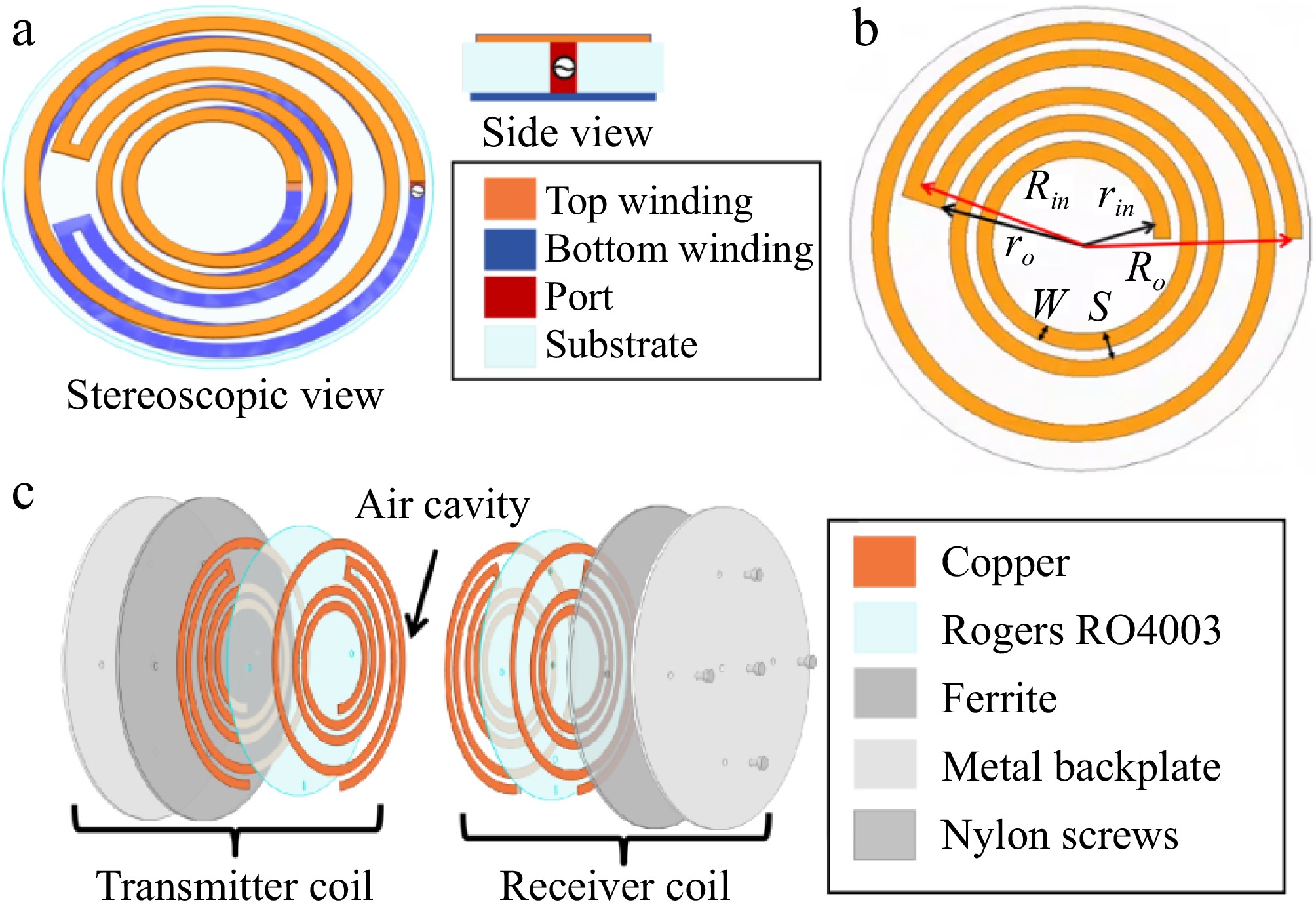
Figure 7.
(a) PAWC structure. (b) The structural diagram of the PAWC on the upper side of the Rogers board. (c) Exploded view of the PAWC coupling structure.
Due to its thinness and susceptibility to damage, it is fixed onto a metal backplate of the same size. The coil is secured to the magnetic backplate by drilling holes in the coil and the magnetic backplate as well as the metal backplate at the corresponding locations, and then utilizing nylon screws through the holes to secure the coil to the magnetic backplate. As shown in Fig. 8, the overall coupling structure is a combination of two identical unilateral structures.
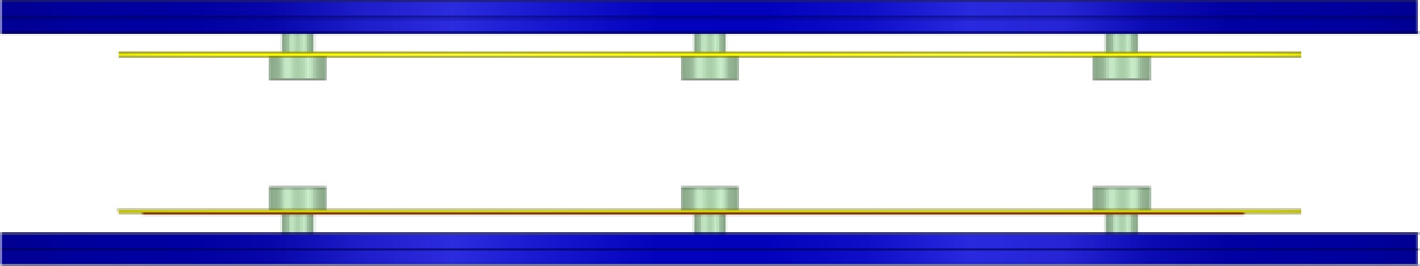
Figure 8.
Overall coupling structure.
As shown in Fig. 9, the magnetic fields are well concentrated between the coupling structures, and there is basically no magnetic field leakage. In practical applications, this reduces electromagnetic interference to other integrated structures.
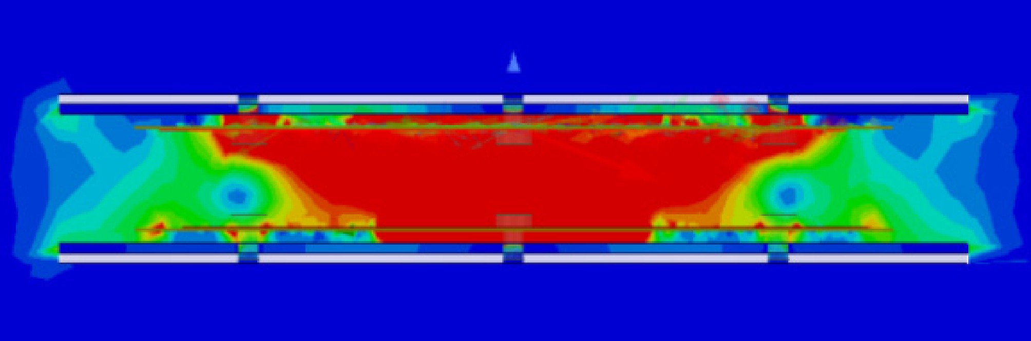
Figure 9.
Magnetic field distribution between coupled structures.
The coupling structure designed in this section finally realizes the two impedance states mentioned above, as illustrated in Fig. 10. The input impedance of the unilateral PAWC varies with frequency, as shown in Fig. 10a. At 13.56 MHz, the real and imaginary parts of its impedance can reach approximately 10 and 6 kΩ, respectively, with the impedance value approaching infinity. When the receiver approaches and positions itself on the charging location near the TX coil, the spatial permeability between the coils changes, consequently inducing a frequency shift in the system. This physical effect automatically adjusts the SCF to the optimal operating frequency of 13.56 MHz, where the imaginary part of the transmitter coil's impedance precisely reaches zero. This unique characteristic enables the system to achieve optimal power transfer efficiency without requiring additional compensation networks.
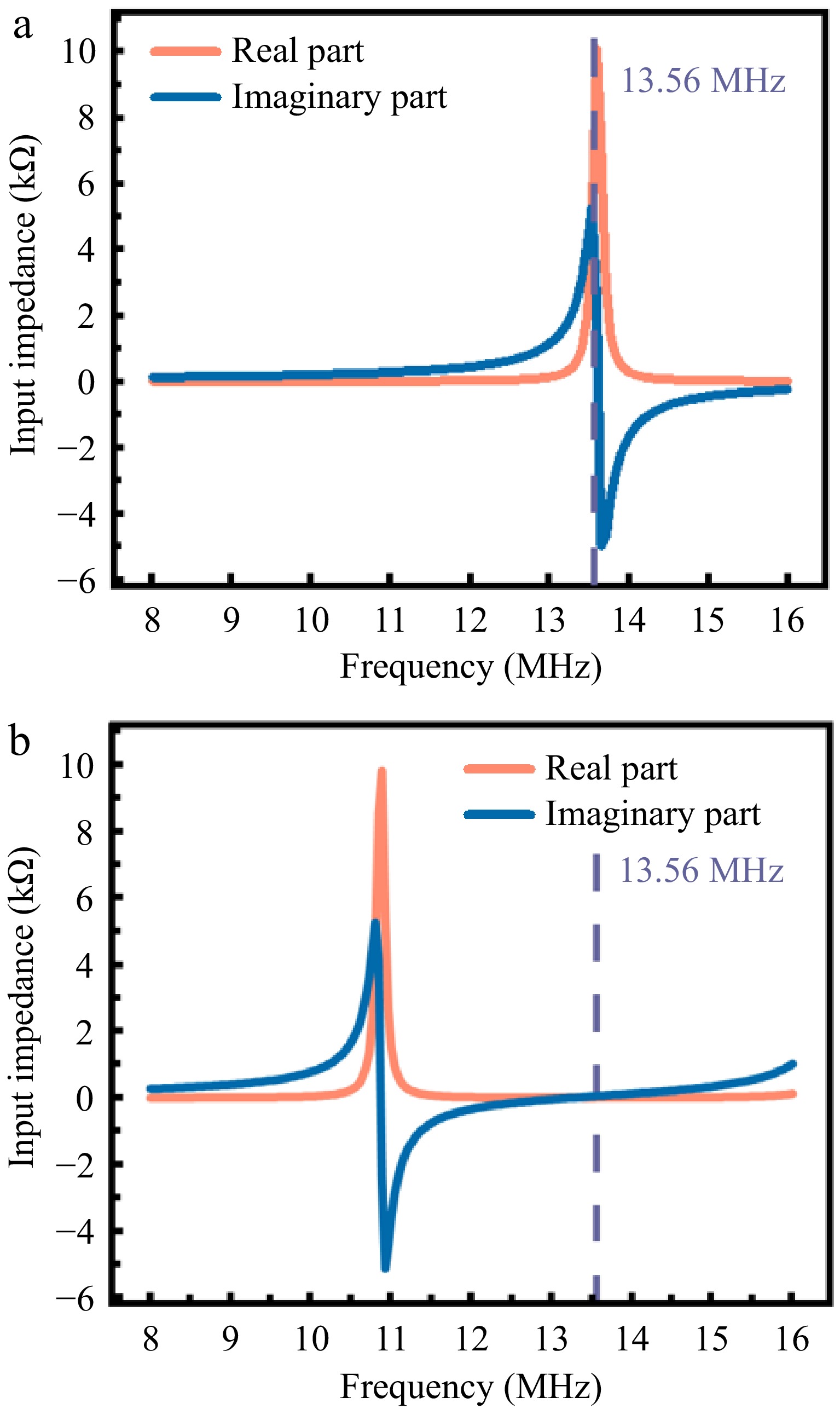
Figure 10.
(a) The relationship between input impedance and frequency of the unilateral PAWC. (b) The relationship between input impedance and frequency for coupled bilateral PAWC.
-
This section presents the experimental validation, which primarily consists of the following key experimental procedures: First, the precision fabrication and manufacturing of the PAWC prototype were completed; second, the mode-switching functionality between OCF and SCF was systematically verified; finally, through the establishment of a test platform, quantitative testing, and analysis were conducted on the system's power transfer efficiency and constant-current characteristics.
Prototype fabrication and switching function validation
-
Figure 11 depicts the fabricated PAWC structure. The measurement of the coil transmission structure was conducted using an Agilent N5247A vector network analyzer (VNA), as depicted in Fig. 12. At 13.56 MHz, with only the unilateral transmission structure in place, the real part of the impedance is 12.09 kΩ and the imaginary part is 6.66 kΩ, as seen from Fig. 12a. During the test based on the single-sided transmission structure, the coil on the other side was connected to Port 2 of the VNA using an SMA connector. As Fig. 12b demonstrates, when the distance to the TX coil was 5 mm at a frequency of 13.56 MHz, the real part of the impedance dropped to 2.99 Ω, and the imaginary part was 0.298 Ω.
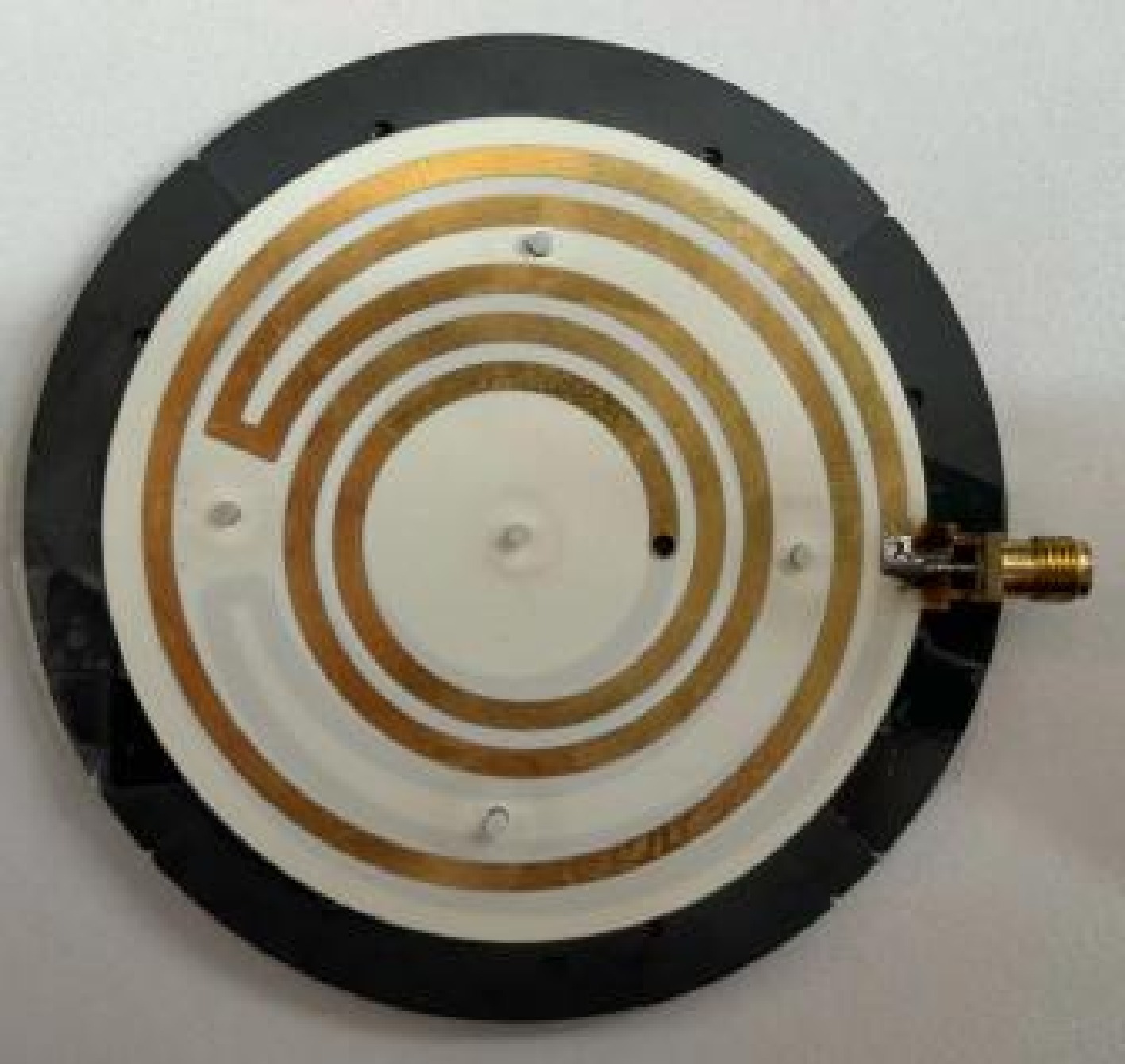
Figure 11.
Fabricated PAWC structure.
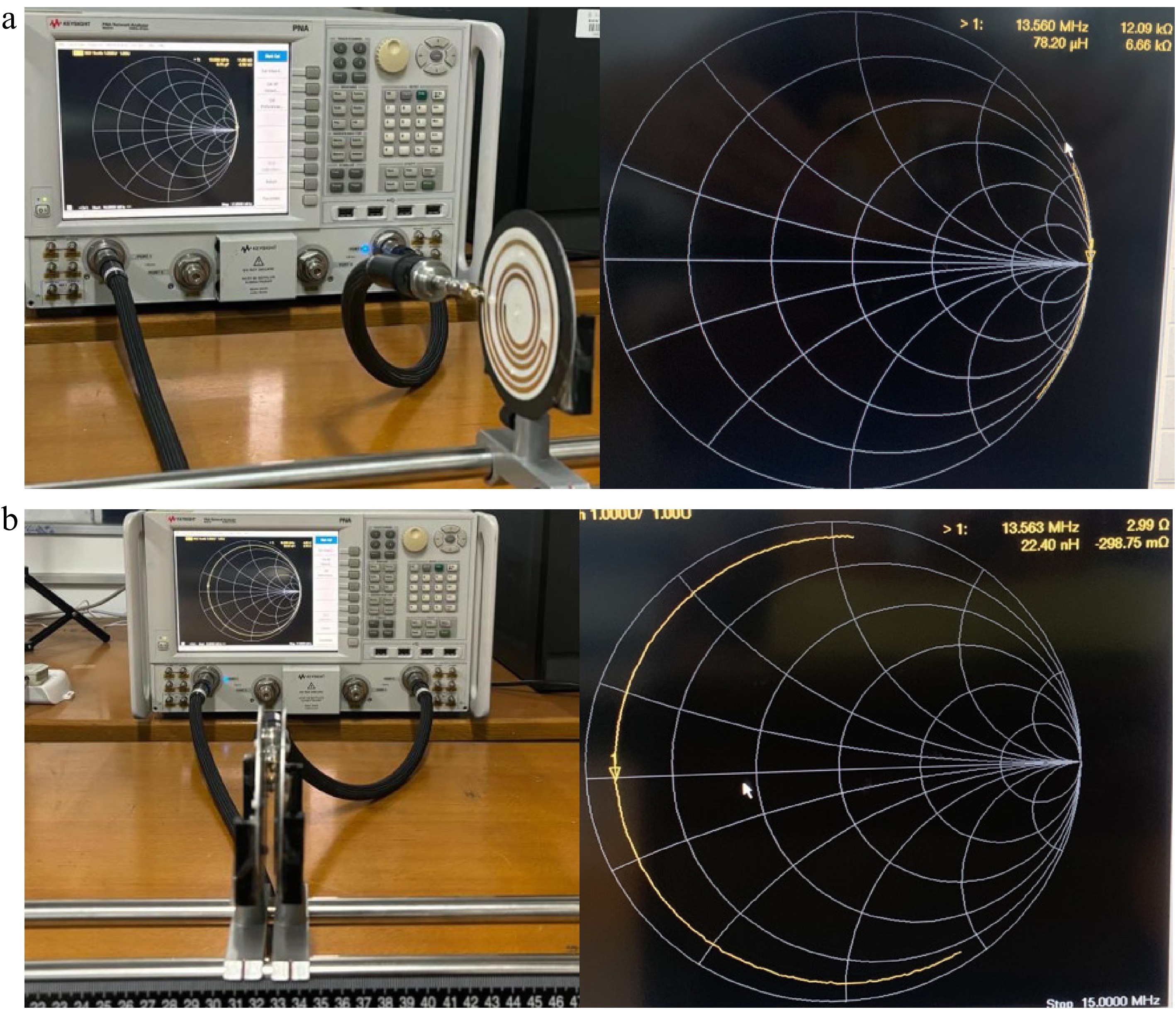
Figure 12.
Experimental setups of the fabricated PAWC. (a) Unilateral transmission structure testing. (b) Bilateral transmission structure testing.
To comprehensively characterize the frequency-dependent impedance behavior, the measured S2P files were imported into Advanced Design System circuit simulation software for visualizing and analyzing the impedance characteristics at both coil terminals, with detailed comparison against simulation results.
As shown in Fig. 13, excellent agreement between measurements and simulations was observed: (1) When only the transmitter coil was present, the system exhibited high-impedance characteristics at 13.56 MHz (OCF); (2) With the receiver positioned for charging, the system automatically transitioned to SCF at the identical 13.56 MHz frequency, where the imaginary part of impedance reached zero.
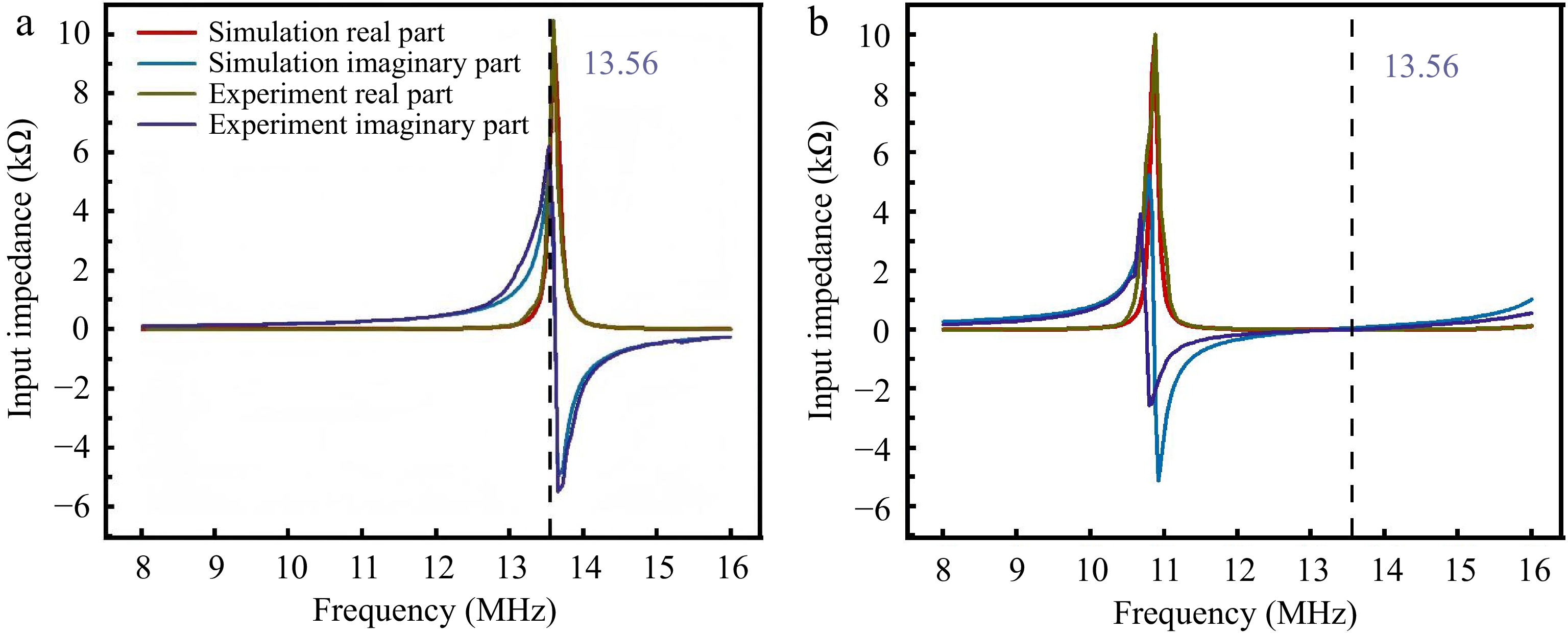
Figure 13.
Experimental-simulation comparison of PAWC impedance characteristics. (a) Transmitter-only operation with OCF mode at 13.56 MHz. (b) 5 mm receiver spacing with SCF mode impedance at 13.56 MHz.
The experimental results clearly validate the theoretical analysis presented earlier, demonstrating that changes in the relative position of PAWCs induce a transition between two distinct impedance states.
To validate the position-sensing-based power transfer switching capability of the PAWC system, experimental tests were conducted with an AC power source connected to the TX coil. As shown in Fig. 14a, when the RX coil was positioned at a larger separation distance, the system impedance significantly increased to approximately 13 kΩ, exhibiting an equivalent open-circuit state with zero current and no power output from the transmitter, fundamentally eliminating the overcurrent risk inherent in conventional S-S compensation topologies under no-load conditions. With the receiver moved to the charging position, as shown in Fig. 14b, the system impedance dropped sharply to several ohms, with the imaginary part reaching zero, thereby generating substantial sinusoidal current.
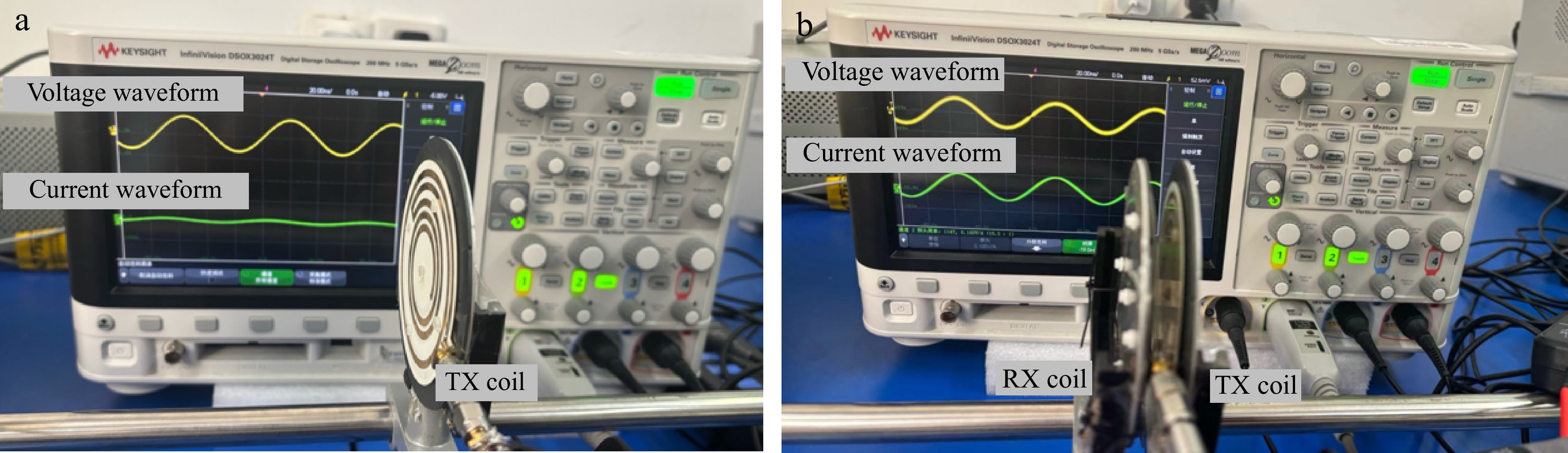
Figure 14.
Switching state verification of PAWC. (a) TX coil only-safety cutoff mode and zero-current protection. (b) Receiver in charging position, showing high-efficiency transfer mode and auto-activation feature.
Subsequent separation tests confirmed the system's reversion to high-impedance characteristics, demonstrating complete consistency with the results in Fig. 14a. These experiments not only verify that PAWC completely resolves the safety hazards of S-S compensated systems during no-load operation but also demonstrate the implementation of position-dependent power transfer switching.
PAWC transmission performance evaluation
-
Figure 15 illustrates the experimental platform for evaluating the transmission performance of a fabricated PAWCs pair. Two PAWCs with identical dimensions were coaxially aligned with a fixed separation distance of 5 mm. In this setup, a DC power source supplied an inverter to generate AC excitation signals for the TX coil while the RX coil was connected to an AC load. The waveforms were measured using an oscilloscope. To ensure measurement accuracy, the voltage and current probes of the oscilloscope were calibrated using a standard AC resistor combined with a deskew fixture. This calibration procedure eliminated phase shift errors and ensured that the displayed values precisely matched the actual values of the standard resistor. When a 110 Ω AC load was connected to the system, the voltage and current waveforms at both the transmitting and receiving coils were measured by the oscilloscope, as shown in Fig. 15. These waveform data were used to calculate the transmitted power and the transmission efficiency of the PAWCs. The transmitted power can be calculated using the following formula:
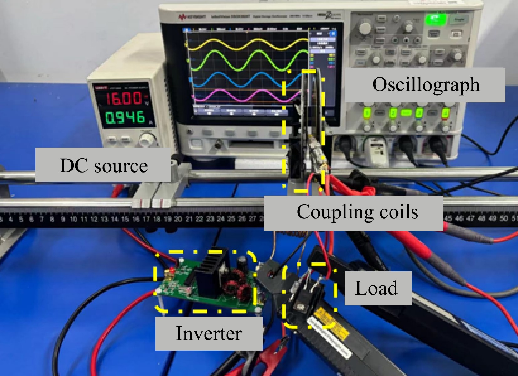
Figure 15.
Experimental setups of PAWC WPT system without compensation circuits.
$ \bar{P} = \dfrac{1}{T}\int\limits_0^T P(t)dt $ (7) where,
$ P(t)=u(t)\cdot i(t)=U_0 I_0 \cos(\omega t+\varphi )cos(\omega t) $ (8) As illustrated in Fig. 16, with a load of 110 ohms, both the input current/voltage and output current/voltage of the coupling coil exhibit standard sinusoidal waveforms while maintaining nearly in-phase relationships between all current and voltage signals. According to Eq. (8), the calculated input power of the coupling coil is 12.9 W with an output power of 12 W, yielding an AC-AC efficiency (ηAC) of 92.8% for the PAWC.
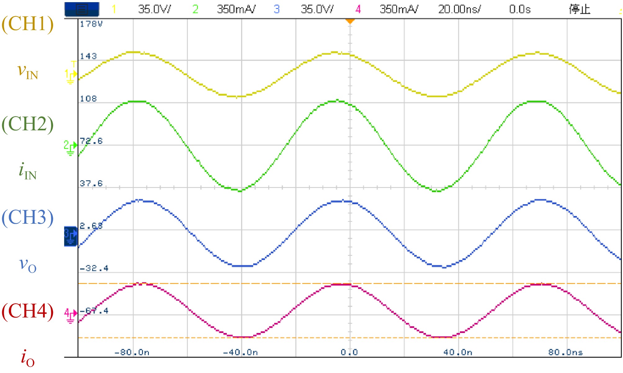
Figure 16.
Measured voltage and current waveforms at both transmitting and receiving coils under 110 Ω AC load condition.
The experimental platform illustrated in Fig. 15 was utilized to systematically evaluate the
${\eta _{AC}}$ 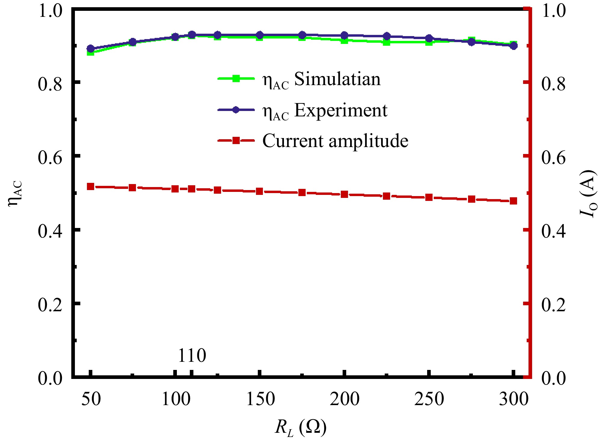
Figure 17.
Measured transmission efficiency of PAWCs across 50−300 Ω AC load range.
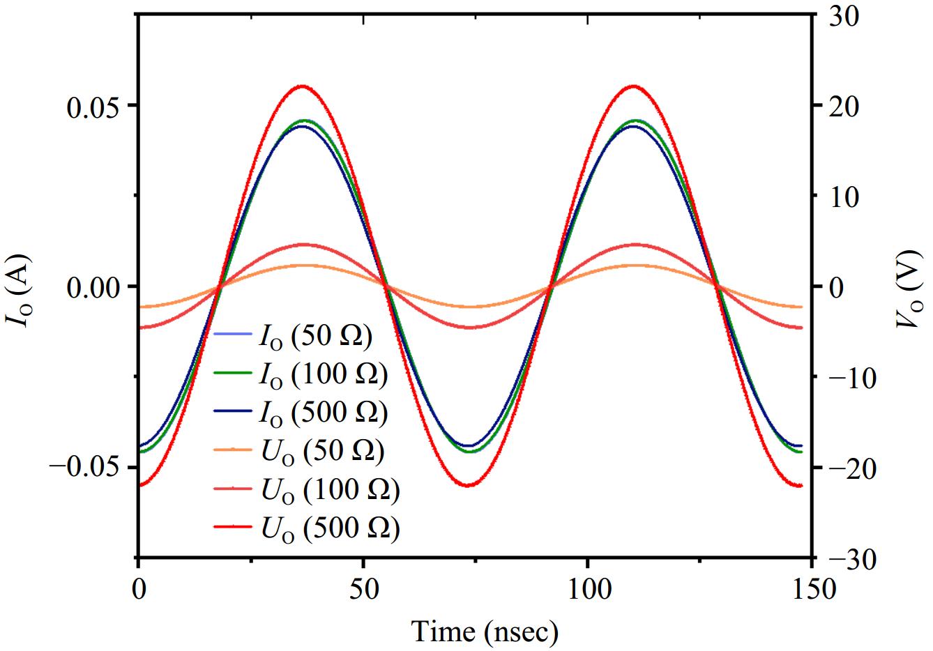
Figure 18.
Waveforms of load-side voltage and current under different loads.
Furthermore, to visually demonstrate the wireless power transfer capability of the PAWC system, a DC-DC WPT system (as illustrated in Fig. 19) was constructed to energize a monitor. The functionalities of each module within the DC-DC WPT system are described as follows: DC source 1 and a signal generator jointly drive the inverter control chip, while DC source 2 provides DC input that is converted to AC via a Class-E inverter module, transmitted through the PAWC coupling module to the rectifier, oscilloscope measurements of waveforms at each node. The circuit measurements confirm that DC Source 2 provides an input of 18 V/0.85 A, corresponding to an input power of 15.3 W. This value is also displayed on the source's screen in Fig. 19. With a DC-DC conversion efficiency of 75%, it delivers 13 V/0.885 A (output power: 11.5 W) to the monitor module, successfully achieving display operation. This platform also enables verification of the system's safety performance under no-load conditions. To further assess the automatic shutdown functionality of the PAWC system, the receiver module can be physically decoupled from the DC-DC system test platform (as depicted in Fig. 20). In this configuration, only the transmitter remains energized, and measurements from DC Source 2 reveal that the input current asymptotically approaches zero under a constant 18 V DC supply voltage, confirming negligible power influx into the system. This observation indicates that the transmitter autonomously initiates shutdown upon receiver disengagement.
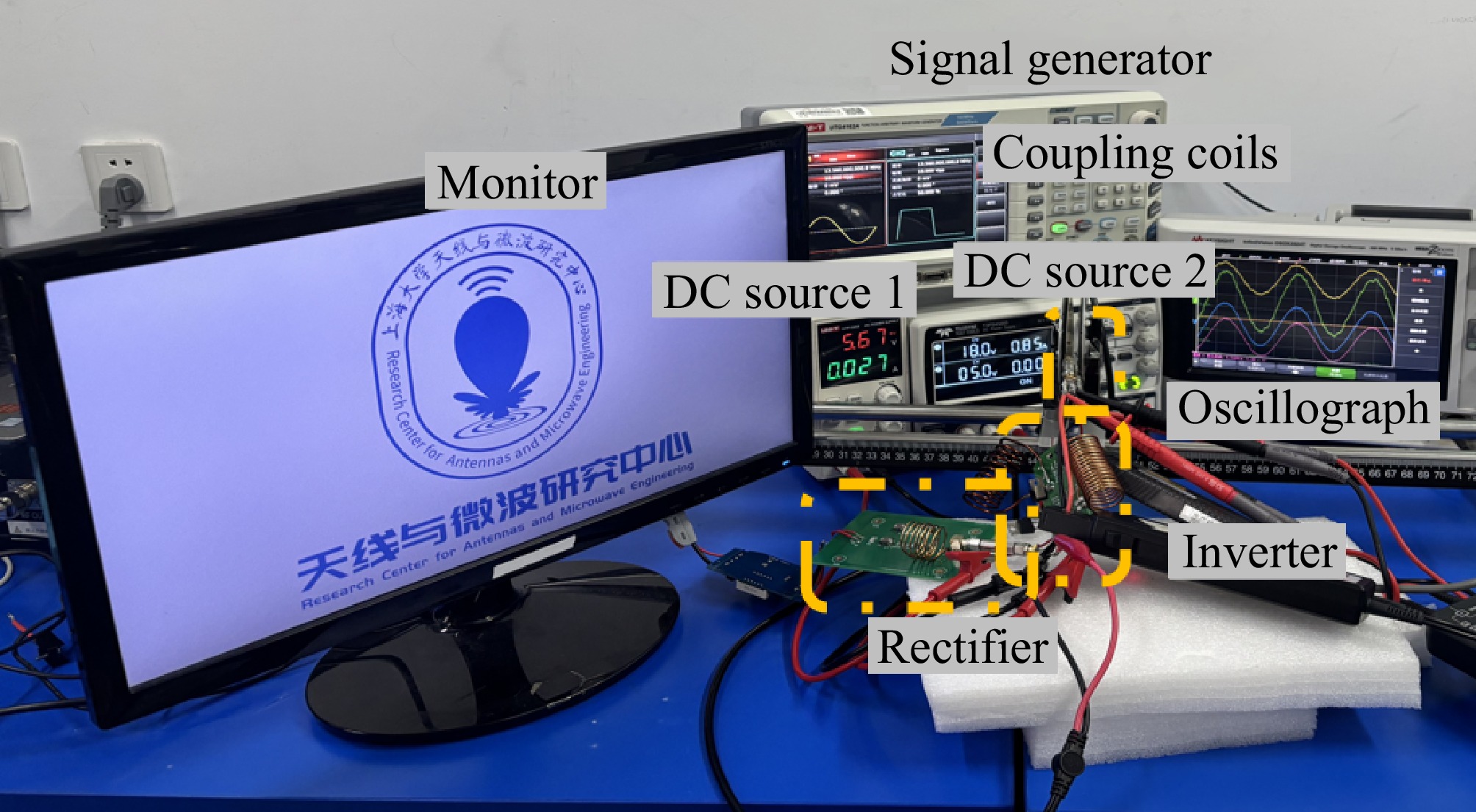
Figure 19.
Test platform for DC-DC systems based on PAWC (coil spacing: 5 mm), used in monitor illumination experiments.
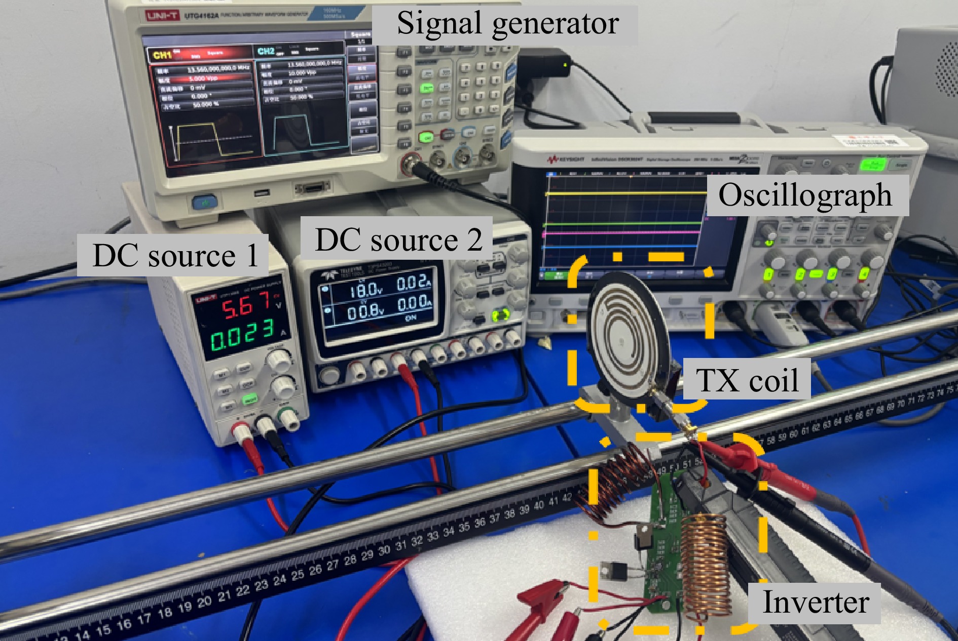
Figure 20.
PAWC system automatic shutdown validation via receiver disconnection.
-
The proposed PAWC-based WPT system addresses critical limitations of conventional S-S and P-P compensation topologies by leveraging the dynamic impedance characteristics of planar alternative winding coils combined with magnetic backplates. Unlike S-S compensation, which suffers from hazardous primary current surges under no-load conditions, the PAWC structure inherently maintains a high-impedance (open-circuit) state when the receiver is absent, eliminating safety risks without additional control mechanisms. While P-P compensation avoids no-load overcurrent issues due to its parallel resonance behavior, its resonant frequency instability under varying coupling and load conditions has restricted its practical adoption. The PAWC demonstrates load-independent frequency stability while achieving highly efficient constant-current output across a wide load range, effectively overcoming the frequency drift issue inherent in conventional P-P compensation due to load sensitivity. Moreover, the PAWC system enables automatic power transfer switching solely through the physical displacement of the RX coil. Compared to conventional solutions relying on additional sensors and switching control modules, this design not only significantly simplifies the system architecture but also demonstrates superior operational reliability. The PAWC structure simplifies system architecture through position-based switching while simultaneously resolving the no-load safety issues inherent in conventional topologies and maintaining load-independent frequency stability, thereby providing a safer and more reliable solution for WPT systems.
-
This study introduces a PAWC system characterized by the integration of magnetic backplates on both sides of the dielectric substrate. The system exhibits unique operational characteristics. During no-load operation, the TX coil demonstrates high-impedance properties (real part 12.09 kΩ, imaginary part 6.66 kΩ), effectively eliminating overcurrent risks that are inherent in conventional S-S compensation topologies under no-load conditions. When the receiver is positioned in the charging area, the spatial permeability variation caused by its magnetic backplate automatically tunes the system to the SCF, where the imaginary part of the impedance precisely reaches zero, facilitating high-efficiency power transfer (up to 92.8%) without the need for any compensation networks. Notably, the system achieves autonomous start-stop control of power transmission solely through physical position changes, thereby eliminating the need for additional switching modules that are required by conventional solutions. Experimental validation demonstrates that the PAWC maintains over 90% efficiency across a wide load range (50−300 Ω) while exhibiting load-independent constant-current output characteristics. This innovative design, integrating high-efficiency energy transfer, no-load protection, and self-adaptive switching functionality, offers new technical approaches for the development of wireless charging systems.
This research was funded by the National Natural Science Foundation of China (Grant No. 52207214).
-
The authors confirm their contribution to the paper as follows: study conception and design, draft manuscript preparation: Yi Z, Tao X; data collection: Yi Z, Tao X, Zeng D; analysis and interpretation of results: Tao X, Li M. All authors reviewed the results and approved the final version of the manuscript.
-
The datasets generated during and/or analyzed in the current study are available from the corresponding author on reasonable request.
-
The authors declare that they have no conflict of interest.
- Copyright: © 2025 by the author(s). Published by Maximum Academic Press, Fayetteville, GA. This article is an open access article distributed under Creative Commons Attribution License (CC BY 4.0), visit https://creativecommons.org/licenses/by/4.0/.
-
About this article
Cite this article
Yi Z, Tao X, Zeng D, Li M. 2025. 13.56 MHz magnetic backplate-integrated PAWC wireless power transfer: an innovative switchless control and no-load protection approach. Wireless Power Transfer 12: e023 doi: 10.48130/wpt-0025-0017 

13.56 MHz magnetic backplate-integrated PAWC wireless power transfer: an innovative switchless control and no-load protection approach
- Received: 09 April 2025
- Revised: 29 April 2025
- Accepted: 14 May 2025
- Published online: 27 August 2025
Abstract: This study first proposes a planar alternating winding coil (PAWC) integrating a magnetic backplate, adopting a dual-sided alternating winding architecture on dielectric substrates. The proposed PAWC system features three fundamental characteristics: load-independent constant-current output, broad-range high-efficiency power transfer, and inherent no-load protection. During no-load operation, the transmitter exhibits high-impedance characteristics, effectively entering a zero-current shutdown state that completely prevents the overcurrent risks typical of series-series (S-S) compensated systems. When the receiver approaches the charging position, the system autonomously shifts to a zero-reactance operating mode at the same working frequency, achieving efficient power transfer without supplemental compensation networks. This design enables state switching purely through relative coil positioning, eliminating the need for additional sensing or switching components. Experimental validation confirms 92.8% coil-to-coil transfer efficiency at 5 mm separation, with efficiency exceeding 90% across 50−300 Ω load variations. These advancements offer particular value for safety-critical applications, including smart home ecosystems and medical implants, where the system's self-regulating switching capability and robust efficiency significantly enhance operational reliability.
-
Key words:
- Wireless power transfer /
- Coils /
- Power transmission