-
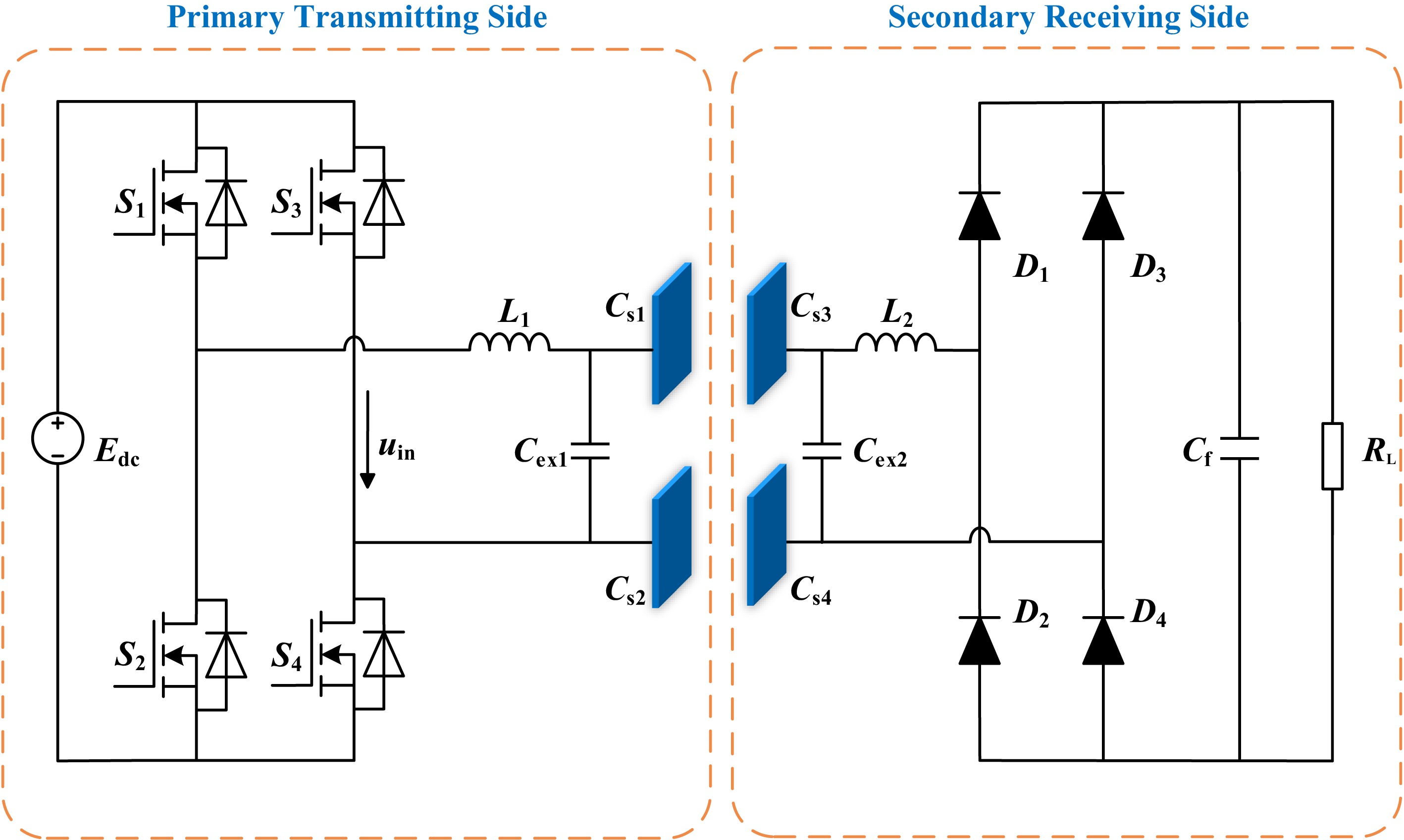
Figure 1.
ECPT system architecture based on double-sided LC compensation topology.
-
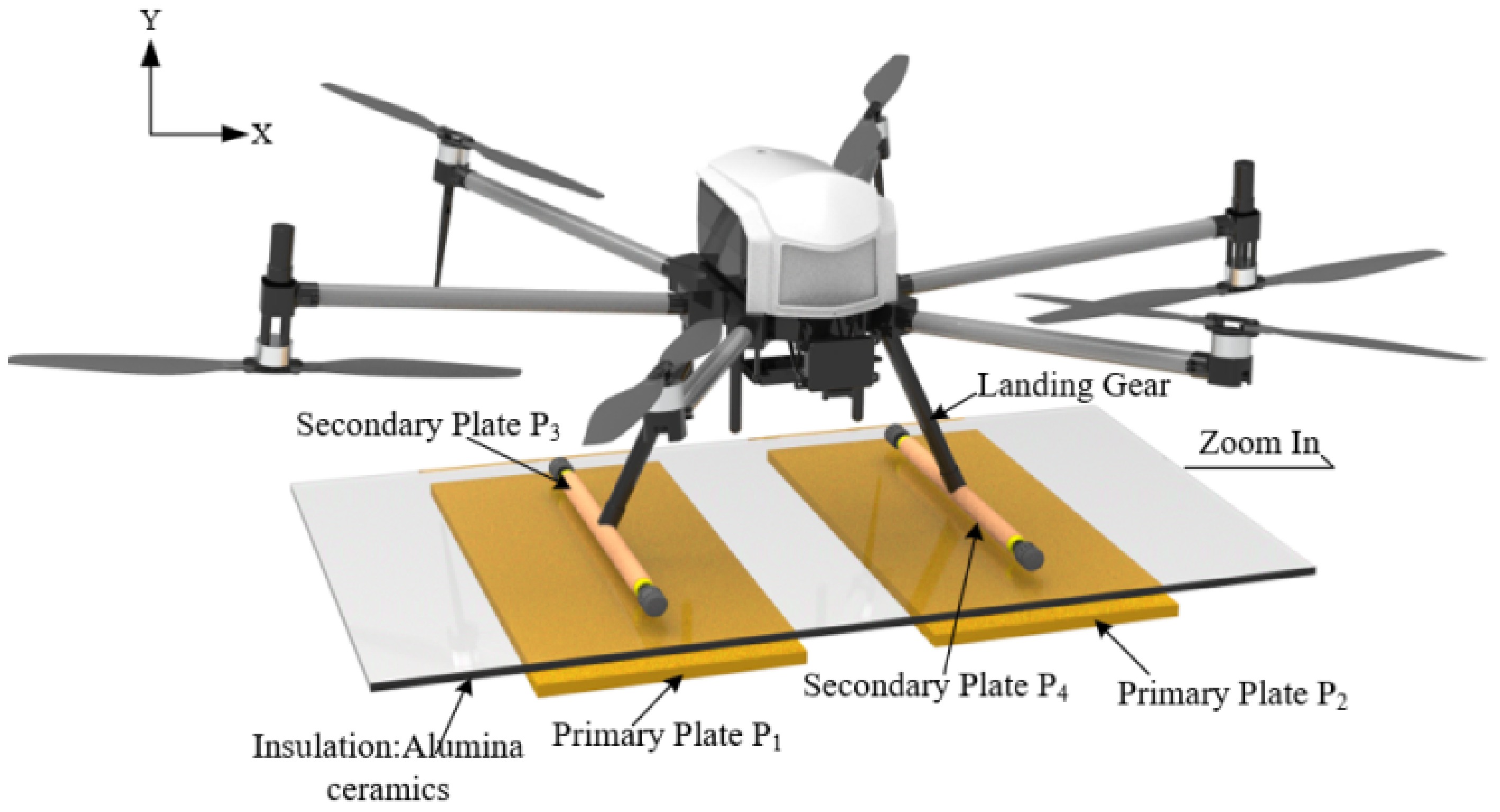
Figure 2.
Schematic diagram of the UAV and its electric field coupling structure.
-
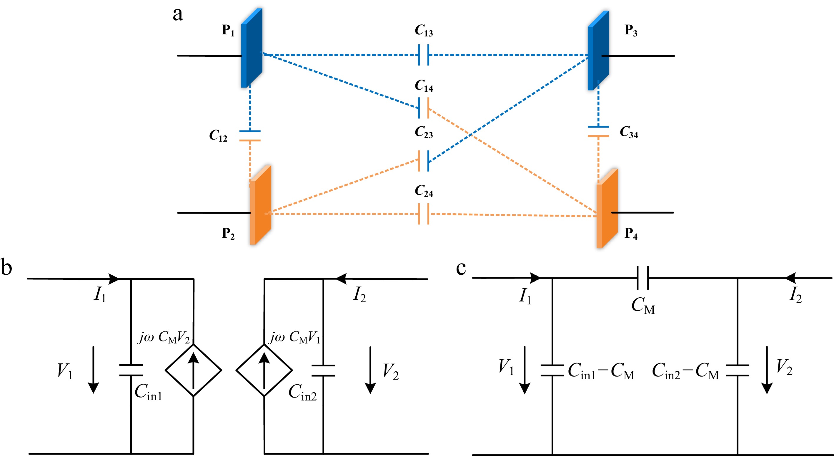
Figure 3.
Equivalent circuit of coupling mechanism. (a) Coupling mechanism model. (b) Current source model. (c) Equivalent π model.
-
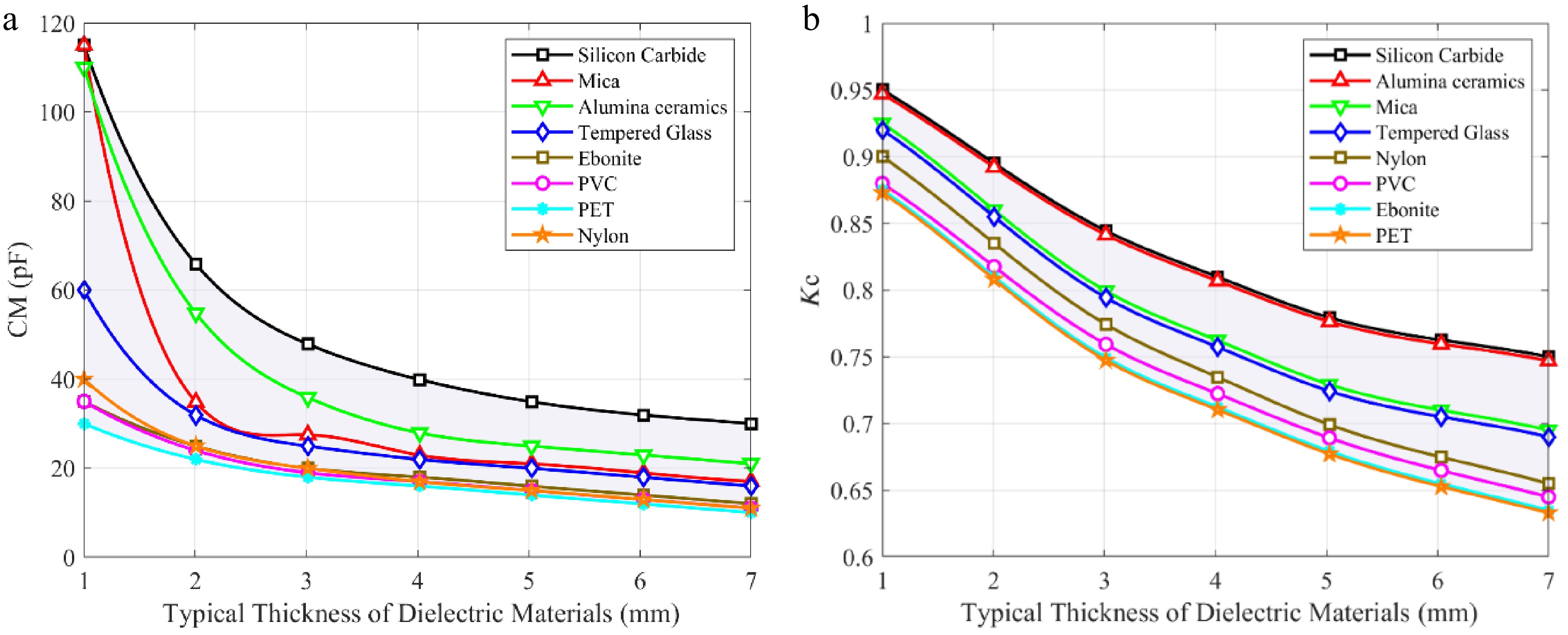
Figure 4.
Coupling mechanism variation curve. (a) Mutual capacitance (b) Coupling coefficient.
-
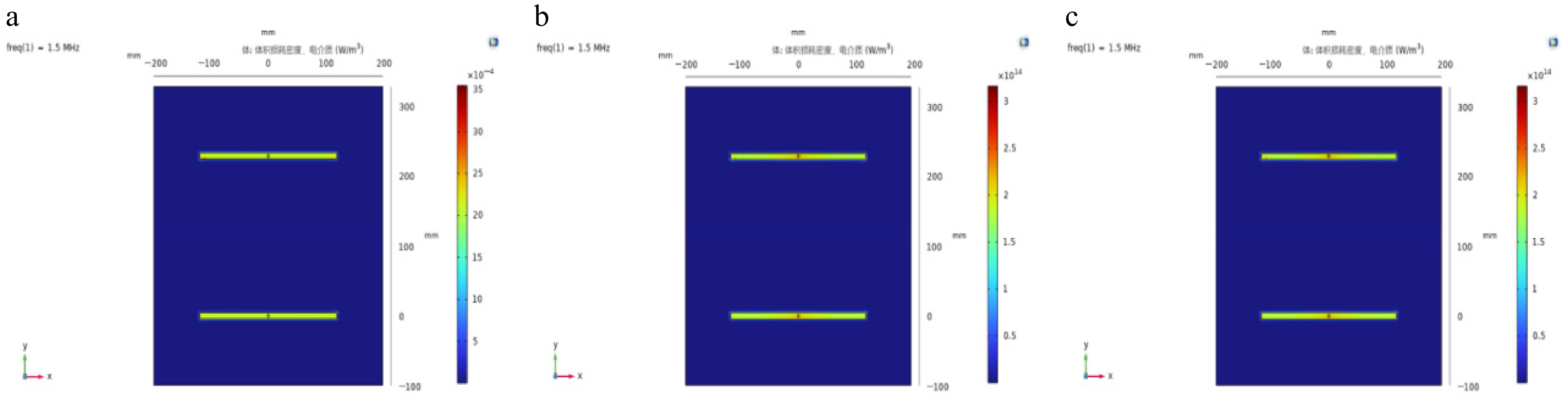
Figure 5.
Power loss density distribution of different typical dielectric materials. (a) Tempered glass. (b) Silicon carbide. (c) Alumina ceramics.
-
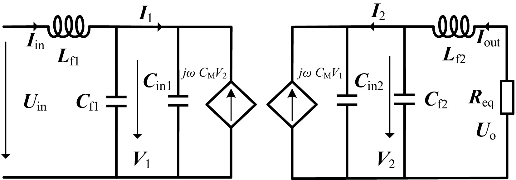
Figure 6.
Bilateral LC type resonant topology under π equivalent model.
-
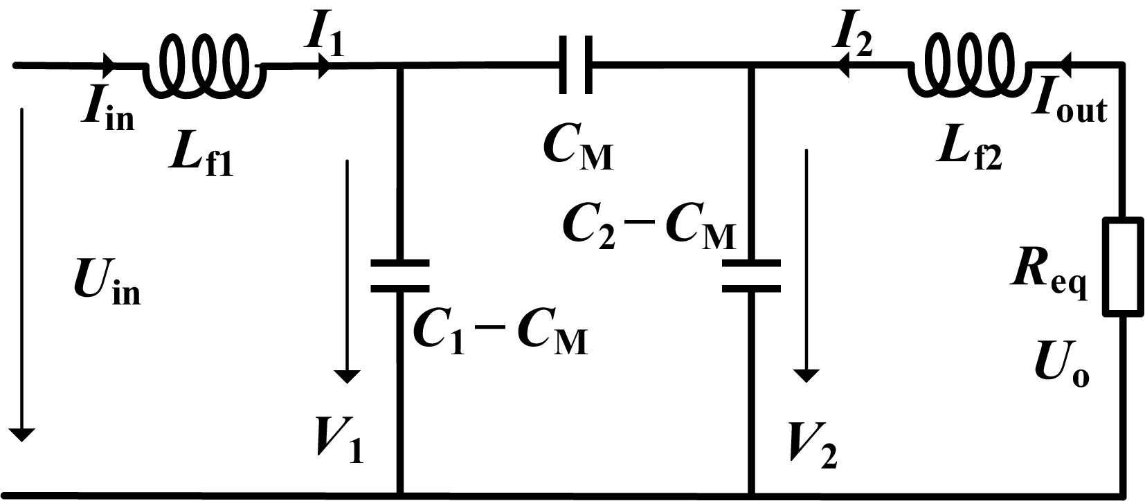
Figure 7.
Equivalent circuit of bilateral LC resonant network under π model.
-
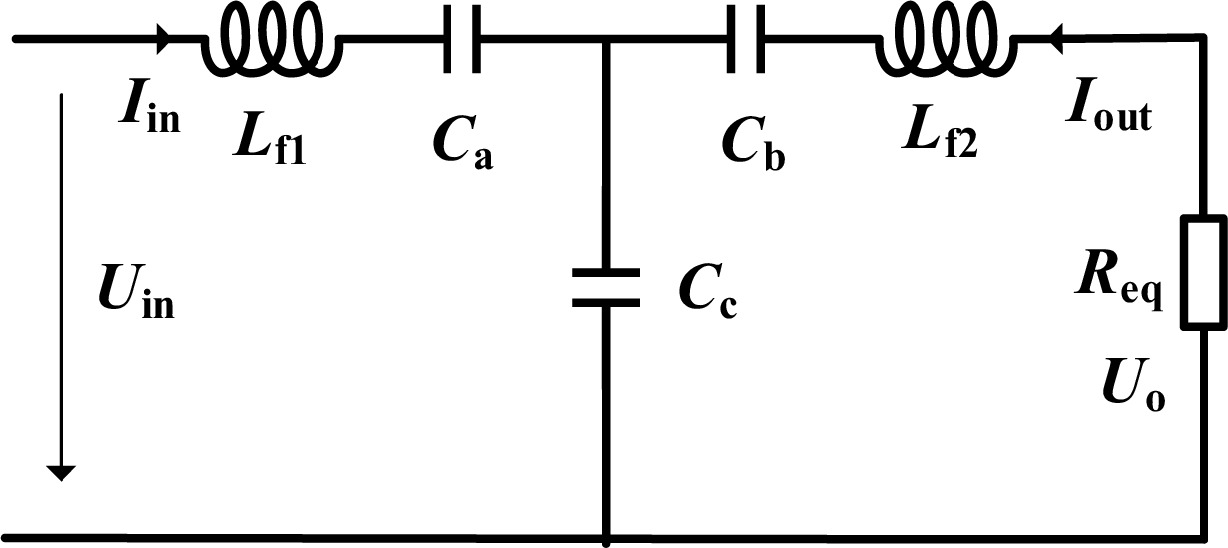
Figure 8.
Equivalent circuit of bilateral LC resonant network under T model.
-
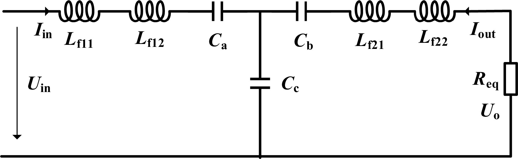
Figure 9.
Equivalent circuit of bilateral LC resonant network after inductor splitting.
-
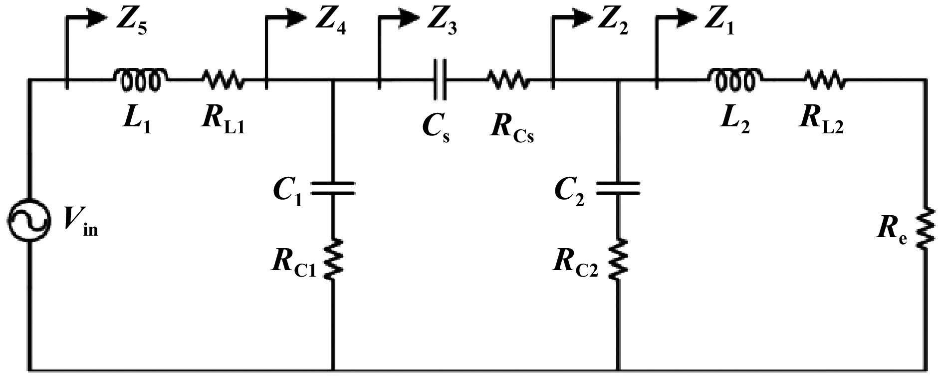
Figure 10.
Equivalent circuit of bilateral LC compensation ECPT system.
-
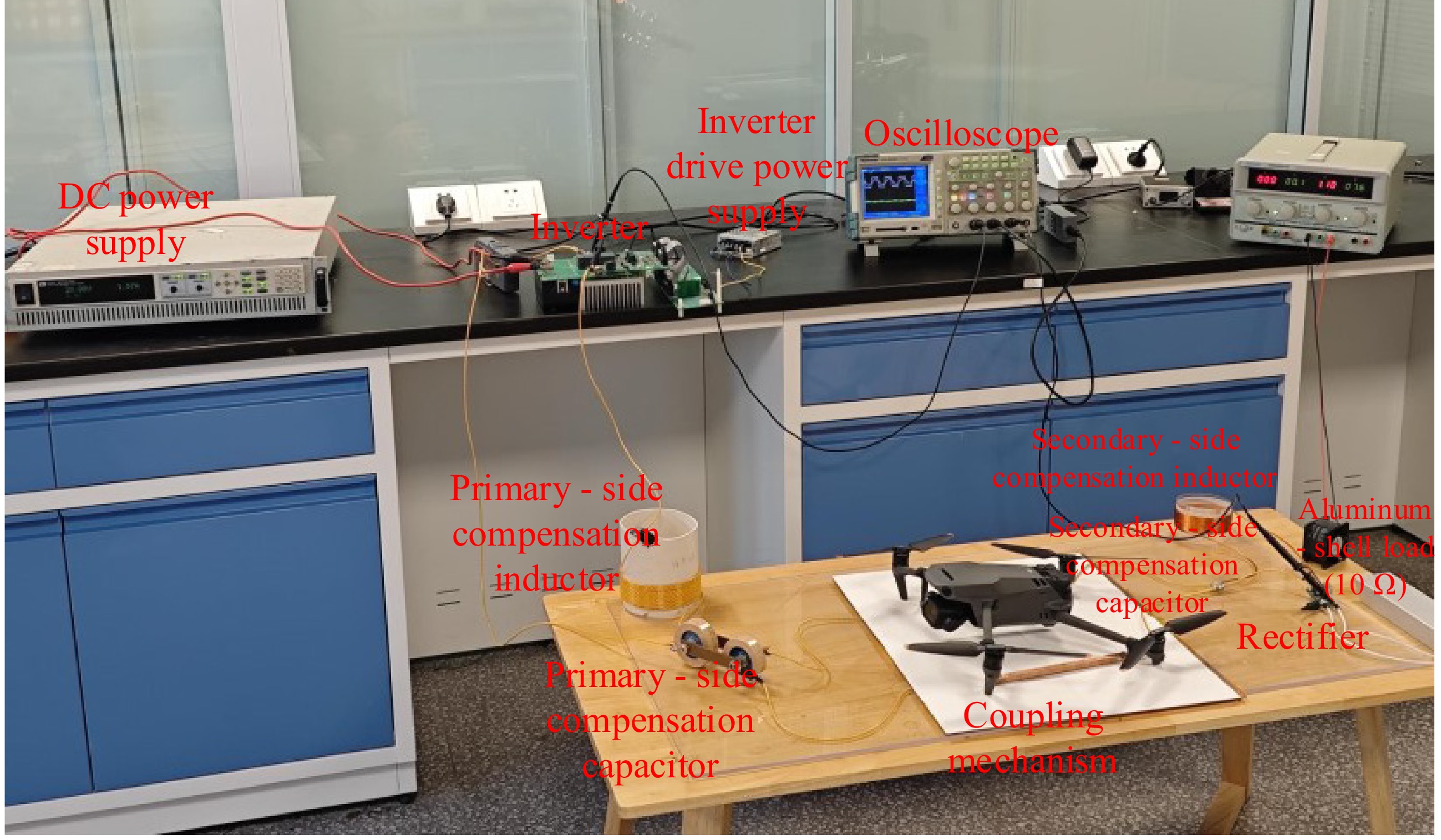
Figure 11.
Experimental prototype of the wireless charging system.
-
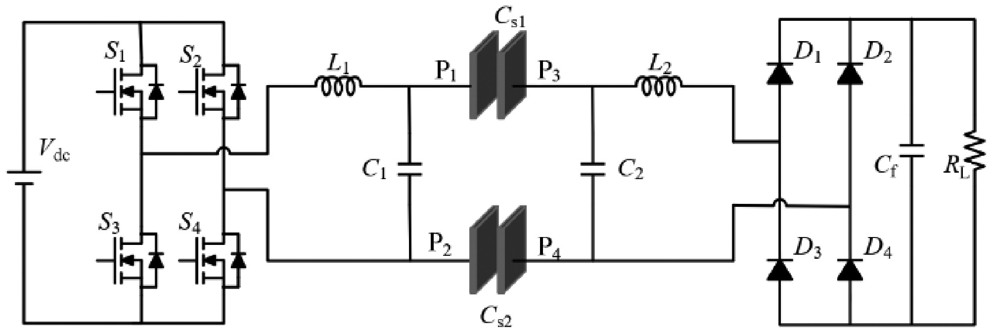
Figure 12.
Block diagram of the experimental system architecture.
-
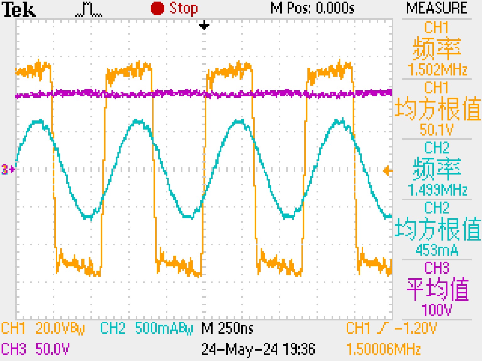
Figure 13.
System waveforms at R = 50 Ω (output power: 200 W, DC-DC efficiency: 87%).
-
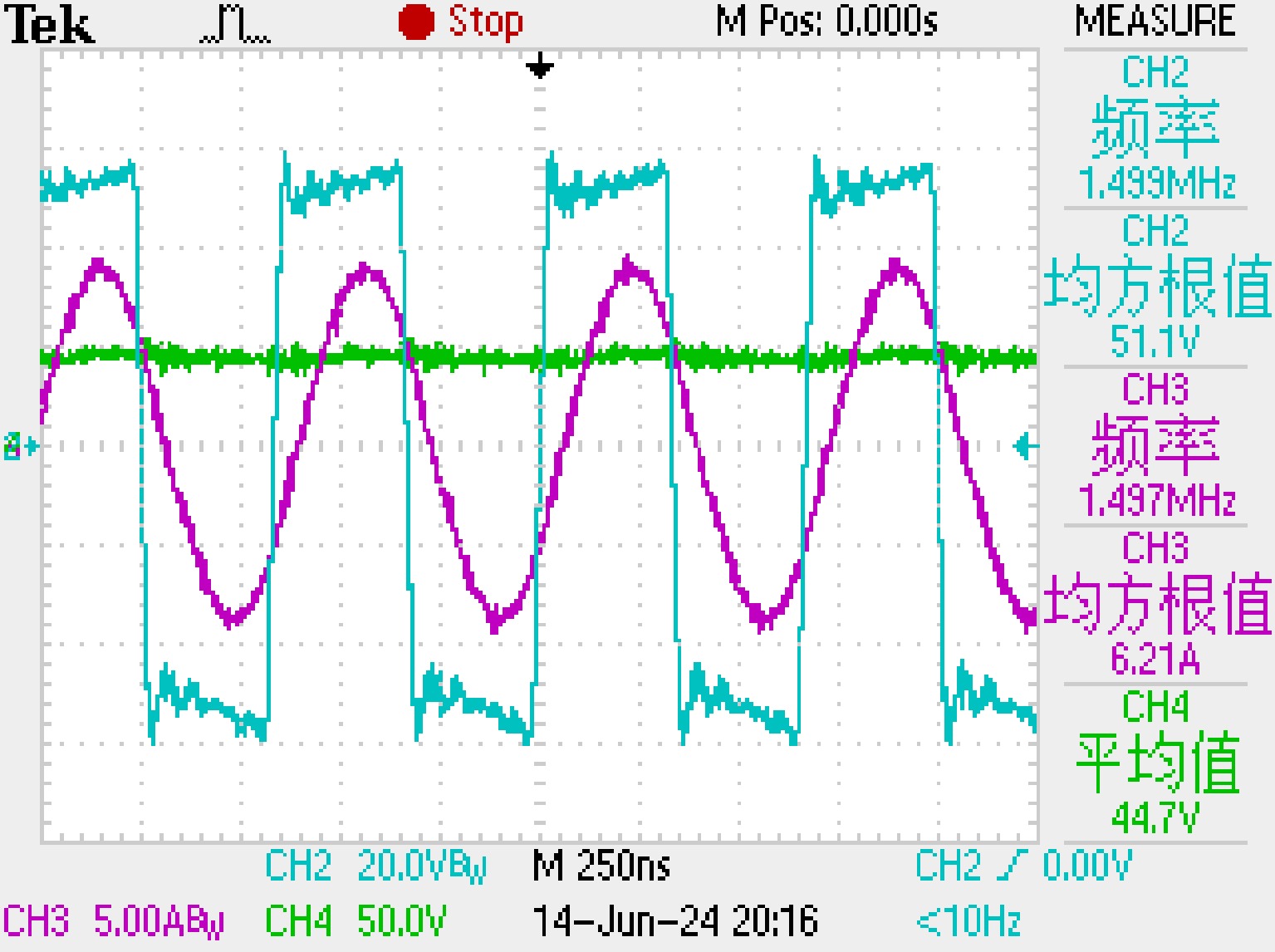
Figure 14.
System waveforms at R = 10 Ω (output power: 200 W, DC-DC efficiency: 84.2%).
-
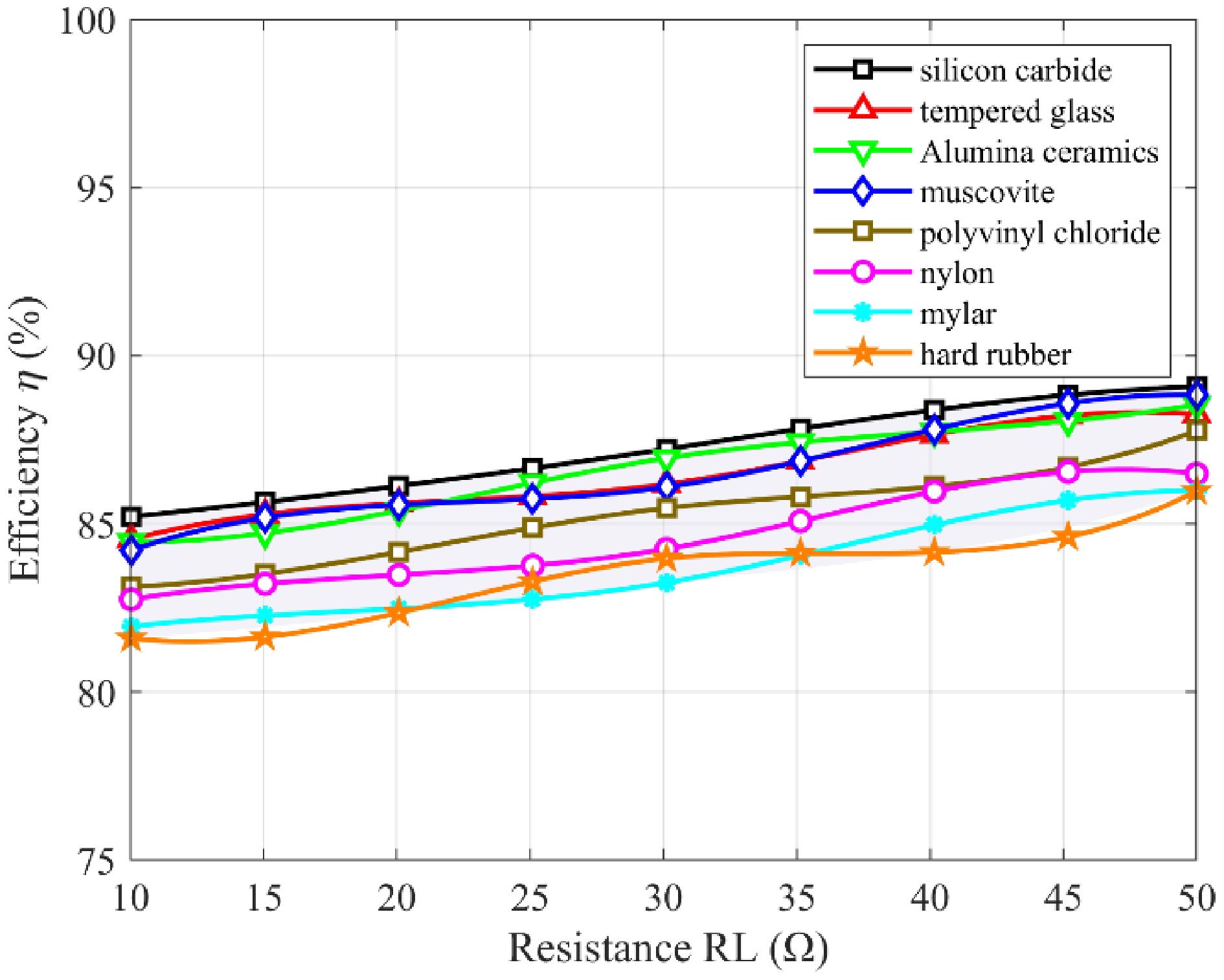
Figure 15.
Variation of DC-DC efficiency under different load resistances.
-
Typical dielectric
materialsRelative complex
dielectric constantCM (pF) Cin1−CM (pF) Cin2−CM (pF) Tempered glass 5.5-j1.2e-10 65.52 11.43 0.111 Silicon carbide 10-j1.2e7 116.22 12 0.110 Muscovite 5.7-j2.41e-11 67.77 11.45 0.111 Alumina ceramics 9.8-j1.2e-10 113.97 11.98 0.110 Hard rubber 3-j1.2e-11 37.27 11.08 0.114 Polyvinyl chloride 3.4-j6e-10 41.8 11.14 0.113 Mylar 3.1-j1.2e-9 38.41 11.1 0.113 Nylon 4-j1.2e-8 48.59 11.23 0.112 Table 1.
Relative complex permittivity of typical dielectric materials and mutual capacitance of coupling mechanisms.
-
Typical dielectric
materialsC12 (pF) C13 (pF) C14 (pF) C23 (pF) C24 (pF) C34 (pF) Tempered glass 11.32 131 0.10535 0.11187 131.27 0.0025 Silicon carbide 11.9 232.3 0.10403 0.11045 232.79 0.00243 Muscovite 11.35 135.52 0.10525 0.11176 135.79 0.00249 Alumina ceramics 11.87 227.8 0.10406 0.11048 228.28 0.00243 Hard rubber 10.97 74.59 0.10772 0.11439 74.72 0.00262 Polyvinyl chloride 11.03 83.64 0.10711 0.11375 83.79 0.00259 Mylar 10.99 76.86 0.10755 0.11421 76.99 0.00261 Nylon 11.12 97.19 0.10643 0.11301 97.37 0.00255 Table 2.
Coupling capacitance of typical dielectric materials.
-
Parameter Expression Parameter Expression YL1 $ \dfrac{1}{j\omega {L}_{1}} $ YL2 $ \dfrac{1}{j\omega {L}_{2}} $ YC1 $ j\omega {C}_{1} $ YC2 $ j\omega {C}_{2} $ Y1 $ j\omega {C}_{1}+\dfrac{1}{j\omega {L}_{1}} $ Y2 $ j\omega {C}_{2}+\dfrac{1}{j\omega {L}_{2}} $ YM $ j\omega {C}_{{\mathrm{M}}} $ YRL $ \dfrac{1}{{R}_{{\mathrm{L}}}} $ Table 3.
Admittances of the circuit components.
-
Parameter Value Parameter Value f (MHz) 1.5 Vdc (V) 50 L1 (μH) 30.7 Cex1 (pF) 330 L2 (μH) 30.7 Cex2 (pF) 330 CM (pF) 33.1 Cin1 (pF) 39.1 Kc 0.0898 Cin2 (pF) 39.1 RL (Ω) 10–50 Table 4.
System parameters.
-
Table 5.
Comparison of UAV ECPT systems.
Figures
(15)
Tables
(5)