


-
Unmanned aerial vehicles (UAVs) have been widely applied in both civilian and military fields due to their strong environmental adaptability, mission execution capability, lightweight structure, and low operational cost[1]. However, limited by current energy storage technologies, UAVs face a fundamental trade-off between the demand for lightweight design and the need for large-capacity batteries to support long-duration missions. As a result, UAVs must be periodically recharged to maintain operation. The two most commonly adopted recharging methods—modular battery replacement and contact-based plug-in charging—both require human intervention, which contradicts the autonomous nature of UAV systems. Additionally, these approaches have inherent drawbacks: battery swapping interrupts mission continuity, while plug-in charging is prone to safety issues such as arcing and contact oxidation. These limitations underscore the need for a highly efficient, fully autonomous charging method tailored for UAV operations.
Wireless power transfer (WPT) technologies, which deliver energy from a power source to a load without direct electrical contact via electromagnetic or microwave fields, have emerged as promising alternatives. Among these, electric field coupling power transfer (ECPT) has attracted increasing attention for UAV applications due to its unique advantages[2,3]: (1) lightweight structure, as ECPT relies on capacitive coupling between transmitter and receiver plates and eliminates the need for bulky magnetic coils; (2) reduced eddy current losses and heating in nearby metallic materials compared to magnetic field-based methods; and (3) greater spatial flexibility in receiver plate alignment, which allows for lateral displacement and rotation without severely affecting performance. These features make ECPT particularly well-suited for UAV wireless charging.
Despite its potential, research on lightweight, high-power ECPT systems for UAVs remains limited, with most studies focusing on circuit topology. For instance, scholar Gao investigates the effects of normalized frequency variation on output power and transfer efficiency in an E-class amplifier with a CLC-S resonant network, yet lacks analysis of circuit designs optimized for high-efficiency conversion[4]. Scholar in Chongqing University addresses the parameter sensitivity of LCL-type ECPT systems and identifies feasible design ranges for four key parameters—load quality factor (Q), inductance ratio (k), and capacitance ratios (a and b)—to balance conversion efficiency and voltage gain stability, offering useful theoretical guidance[5].
However, little attention has been paid to factors such as the choice of plate materials, asymmetrical coupling geometries, dielectric material loss characteristics, and their impact on coupling performance and transmission distance. Furthermore, studies on enhancing electric flux density in irregular asymmetric plate structures, analyzing power loss mechanisms, and conducting multi-objective optimization of the coupling interface are still lacking. Existing ECPT prototypes often suffer from bulky and heavy receiver designs and rely on low-frequency AC charging, resulting in limited power levels and insufficient efficiency for continuous UAV operation. Therefore, a systematic investigation into the design and optimization of a lightweight, high-power-density electric field coupling structure for UAVs is of significant practical and academic value.
In this context, this paper proposes an ECPT-based UAV wireless charging system that achieves high efficiency and practicality without altering the UAV's original structural form. By experimentally evaluating various common dielectric materials, the optimal dielectric is selected. Using a fundamental harmonic approximation method, the equivalent circuit is analyzed to derive system resonance conditions. The final design features a high electric flux density, low loss in both plates and dielectric, and a compact, lightweight structure—contributing to the overall performance and feasibility of electric field-based UAV wireless charging systems.
-
The structure of the ECPT system based on double-sided LC compensation topology is illustrated in Fig. 1. The system comprises a DC power supply Edc, a voltage-source full-bridge inverter constructed with power MOSFET switches S1 to S4, double-sided LC resonant compensation networks, a tightly coupled quadrupole parallel-plate electric field coupling structure, a rectifier circuit, a filter capacitor Cf, and an equivalent load RL. The inclusion of the LC ZVS full bridge suppresses oscillation to a certain extent and significantly reduces switching losses. The operating principle is as follows:
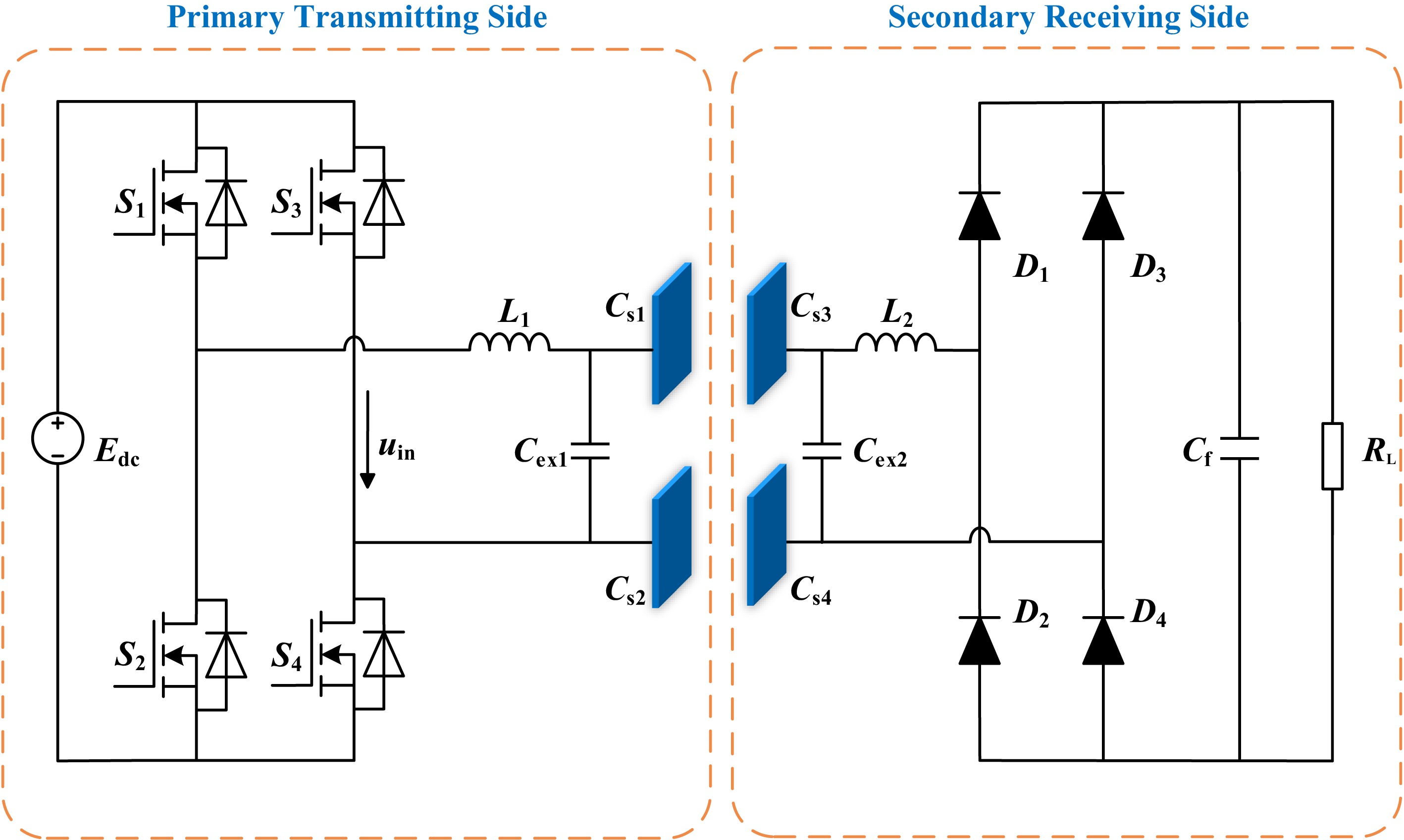
Figure 1.
ECPT system architecture based on double-sided LC compensation topology.
The DC power supply Edc provides electrical energy, which is converted into high-frequency AC by the full-bridge inverter. This AC signal is processed through the transmitter-side double-LC resonant network, which performs frequency tuning and impedance matching before delivering the signal to the transmitting plates. Under the influence of the high-frequency electric field between the coupling plates, displacement currents are induced, enabling contactless power transfer from the transmitter to the receiver. For the wireless charging application of drones, several key design indicators for the coupling mechanism are: (1) the size of the coupling capacitance; (2) the ability to resist misalignment; (3) the weight of the receiving plate. Since drones typically carry equipment such as infrared imaging devices and visible light cameras on their abdomen during operation, the landing gear is a preferable installation position for the receiving mechanism. A model of the coupling mechanism was constructed based on the Comsol simulation platform, including models of planar, concave–convex, cylindrical, and integrated electric field coupling mechanisms. This study focuses on comparing the electric field strength distribution, charge density size and distribution, coupling capacitance, and resistance to offset performance of the four types of asymmetric irregular coupling mechanisms, ultimately analyzing the influencing factors and their patterns. It is concluded that the planar coupling mechanism exhibits the best performance in the aforementioned aspects.
On the receiver side, the double-sided LC resonant network performs impedance matching to convert the coupled electric field energy into voltage/current signals compatible with the load. Finally, the received signal is rectified and filtered by the rectifier circuit and filter capacitor Cf, providing a stable DC output to the load resistor RL[6].
The UAV and its coupling structure are illustrated in Fig. 2. The receiving plates P3 and P4 are mounted on the landing gear of the UAV. During charging, the UAV is positioned above a dielectric platform made of aluminum oxide ceramic, beneath which the transmitting plates P1 and P2 are embedded.
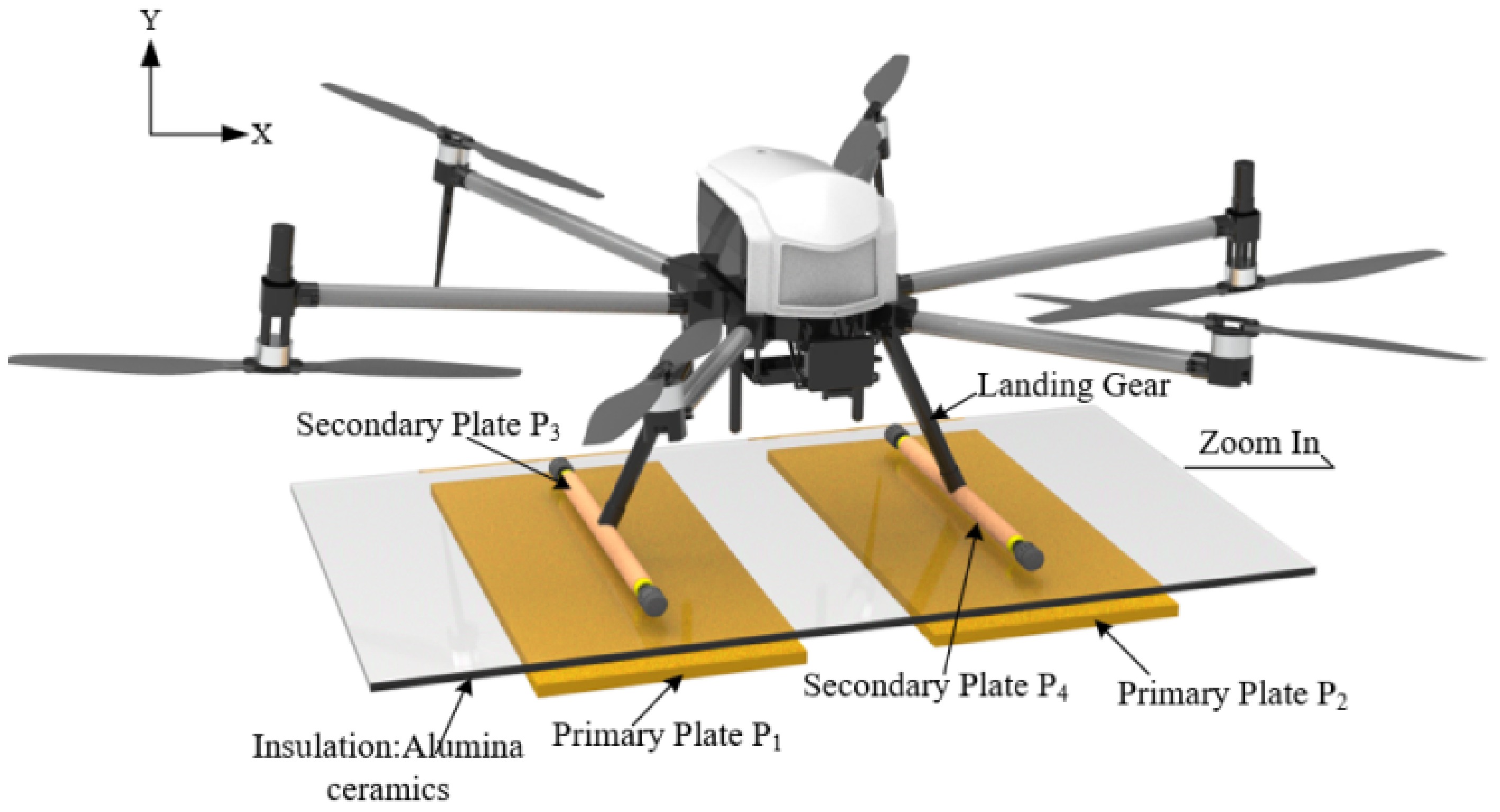
Figure 2.
Schematic diagram of the UAV and its electric field coupling structure.
-
The coupling mechanism is the core part of energy wireless transmission in the electric field wireless energy transmission system. For the electric field coupling mechanism, the coupling capacitance is an important electrical parameter, and the size of the coupling capacitance directly affects the transmission power capability of the system. Therefore, this chapter systematically analyzes the influence of typical dielectric materials on the coupling mechanism to select the optimal dielectric material for the coupling mechanism[7].
Analyze the typical six-capacitor coupling model, as shown in Fig. 3. Among them, C13 and C24 are the coupling capacitors facing the electrode plate, representing the energy transfer component of the coupling electric field. The cross-coupling capacitors C14 and C23, as well as the parasitic capacitors C12 and C34, are the stray capacitors, representing the overlapping component of the coupling electric field. Although the stray capacitance is smaller compared to the coupling capacitance of the opposite electrode plate, it cannot be ignored for the accuracy of the equivalent circuit. The coupling mechanism can be further simplified into a current source model and an equivalent π model to more clearly reflect the connection between the ECPT system's power transmission and reception ends, as shown in Fig. 3b, c. By deduction, Cin1, Cin2, the mutual capacitance CM and coupling coefficient Kc can be expressed as[8,9]:
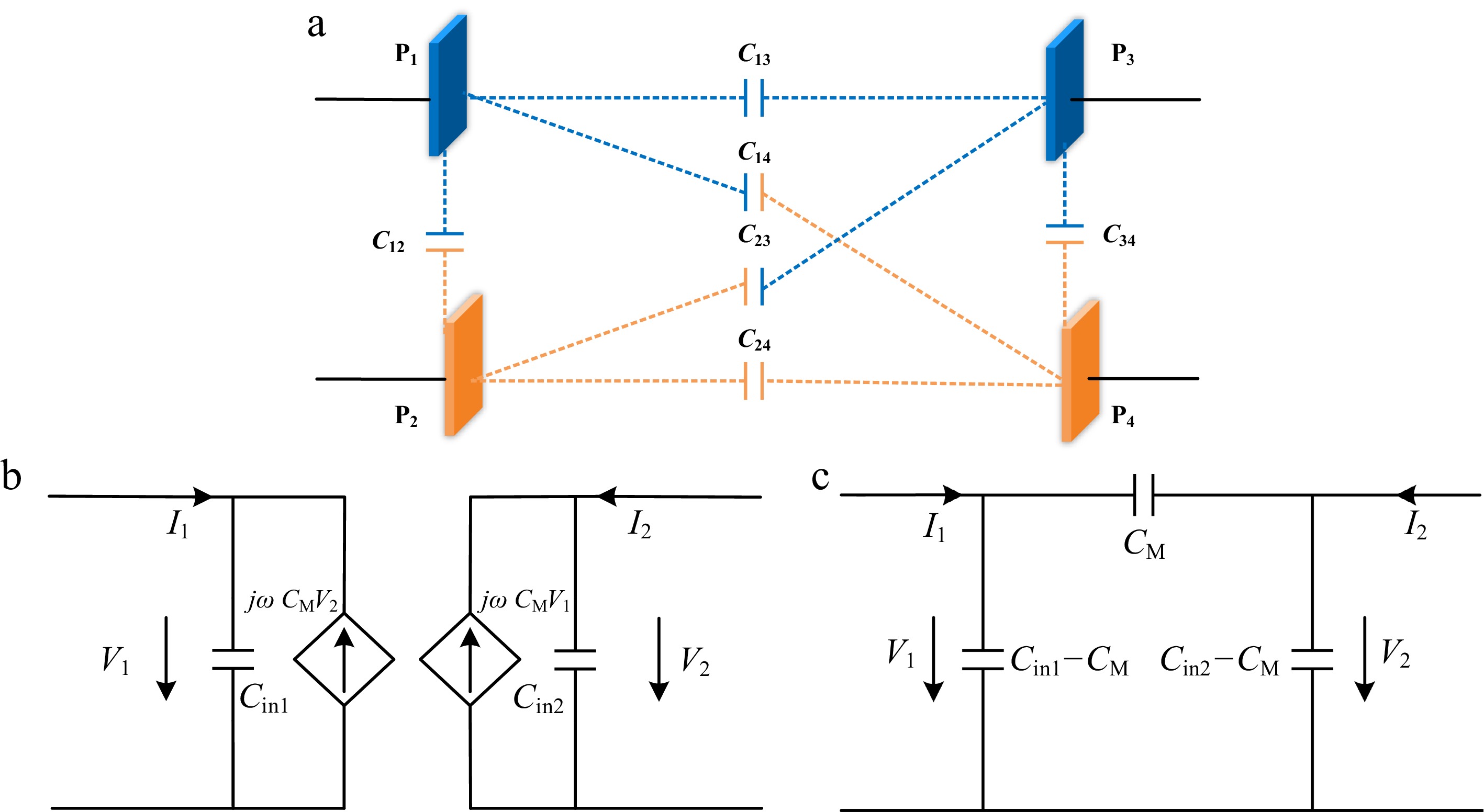
Figure 3.
Equivalent circuit of coupling mechanism. (a) Coupling mechanism model. (b) Current source model. (c) Equivalent π model.
$ \begin{cases} {C}_{{\mathrm{in}}1}={C}_{12}+\dfrac{({C}_{13}+{C}_{14})({C}_{23}+{C}_{24})}{{C}_{13}+{C}_{14}+{C}_{23}+{C}_{24}}\\ {C}_{{\mathrm{in}}2}={C}_{34}+\dfrac{({C}_{13}+{C}_{24})({C}_{14}+{C}_{24})}{{C}_{13}+{C}_{14}+{C}_{23}+{C}_{24}}\\ {C}_{{\mathrm{M}}}=\dfrac{{C}_{13}{C}_{24}\text-{C}_{14}{C}_{23}}{{C}_{13}+{C}_{14}+{C}_{23}+{C}_{24}}\\ {K}_{{\mathrm{c}}}=\dfrac{{C}_{{\mathrm{M}}}}{\sqrt{{C}_{{\mathrm{in}}1}{C}_{{\mathrm{in}}2}}} \end{cases} $ (1) Using a typical flat plate coupling mechanism with a determined size, modify the dielectric material to obtain the effect of the typical dielectric material on the coupling capacitance. As shown in Tables 1 and 2. It can be seen that the coupling capacitance is only related to the real part of the relative complex dielectric constant of typical dielectric materials and not to the imaginary part. For C14 and C23, the larger the real part of the relative complex dielectric constant, the smaller the cross-coupling capacitance. However, since the size of the cross-coupling capacitance is only about 0.1 pF, it can be basically ignored. For parasitic coupling capacitors C12 and C34, the larger the real part of the relative complex dielectric constant, the larger C12 and the smaller C34. However, due to the relatively long distance between the two receiving plates located on the landing gear of the drone, the size of C34 is only about 0.0025 pF, which can be basically ignored. The size variation range of C12 under different typical dielectric materials is around 1 pF. For the coupling capacitance of the electrode facing the coupling capacitor, the larger the real part of the relative complex dielectric constant, the larger C13 and C24, and the larger the range of variation, which can reach 160 pF. Therefore, it has a significant impact on the numerical value of the mutual capacitance CM.
Table 1. Relative complex permittivity of typical dielectric materials and mutual capacitance of coupling mechanisms.
Typical dielectric
materialsRelative complex
dielectric constantCM (pF) Cin1−CM (pF) Cin2−CM (pF) Tempered glass 5.5-j1.2e-10 65.52 11.43 0.111 Silicon carbide 10-j1.2e7 116.22 12 0.110 Muscovite 5.7-j2.41e-11 67.77 11.45 0.111 Alumina ceramics 9.8-j1.2e-10 113.97 11.98 0.110 Hard rubber 3-j1.2e-11 37.27 11.08 0.114 Polyvinyl chloride 3.4-j6e-10 41.8 11.14 0.113 Mylar 3.1-j1.2e-9 38.41 11.1 0.113 Nylon 4-j1.2e-8 48.59 11.23 0.112 Table 2. Coupling capacitance of typical dielectric materials.
Typical dielectric
materialsC12 (pF) C13 (pF) C14 (pF) C23 (pF) C24 (pF) C34 (pF) Tempered glass 11.32 131 0.10535 0.11187 131.27 0.0025 Silicon carbide 11.9 232.3 0.10403 0.11045 232.79 0.00243 Muscovite 11.35 135.52 0.10525 0.11176 135.79 0.00249 Alumina ceramics 11.87 227.8 0.10406 0.11048 228.28 0.00243 Hard rubber 10.97 74.59 0.10772 0.11439 74.72 0.00262 Polyvinyl chloride 11.03 83.64 0.10711 0.11375 83.79 0.00259 Mylar 10.99 76.86 0.10755 0.11421 76.99 0.00261 Nylon 11.12 97.19 0.10643 0.11301 97.37 0.00255 The variation curves of the mutual capacitance CM coupling coefficient Kc of the coupling mechanism composed of different typical dielectric materials at different thicknesses of dielectric materials are shown in Fig. 4a, b, respectively. As can be seen, with the increase of typical dielectric material thickness, the mutual capacitance value of the electric field coupling mechanism gradually decreases, and the parallel capacitance of the equivalent circuit transmitting and receiving ends gradually increases, while the coupling coefficient gradually decreases. The coupling degree between the surface transmitting plate and the receiving plate becomes weaker and weaker. The decrease curve of the coupling coefficient with increasing thickness for coupling mechanisms composed of different typical dielectric materials is basically consistent. However, the larger the real part of the relative complex dielectric constant, the higher the coupling coefficient of the typical dielectric material. When the thickness of the typical dielectric material is 8 mm, there is still a coupling coefficient of nearly 0.75, while the coupling coefficient of the typical dielectric material with a lower real part of the relative complex dielectric constant is only about 0.63.
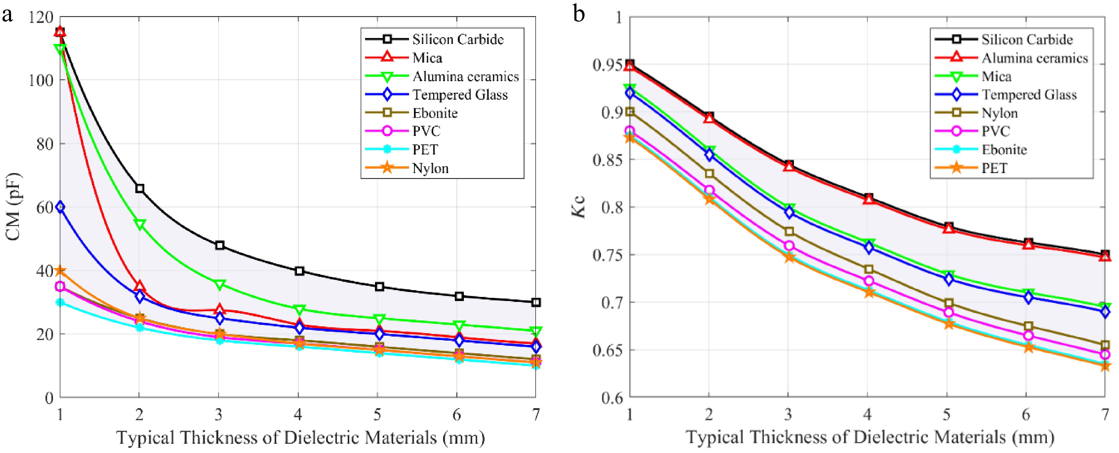
Figure 4.
Coupling mechanism variation curve. (a) Mutual capacitance (b) Coupling coefficient.
Based on the previous analysis and comprehensive consideration, the analysis of the impact of selecting alumina ceramics, tempered glass, and silicon carbide with better performance on power loss density distribution is shown in Fig. 5. The power loss density of different typical dielectric materials is not the same, and it is closely related to the magnitude of the real and imaginary parts of the relative complex permittivity of typical dielectric materials. Among them, although the real part of the relative complex dielectric constant of silicon carbide and aluminum oxide ceramics is not significantly different, due to the fact that silicon carbide belongs to semiconductors and aluminum oxide ceramics belong to insulating materials, the imaginary part of the relative complex dielectric constant of the two is significantly different, reaching nearly 17 orders of magnitude. From Fig. 5b, c, it can be seen that the power loss density of silicon carbide can reach the order of magnitude of 1,014 W/m3, and the total power loss can be calculated as about 6.5e-8 W based on the volume of the dielectric. However, the power loss density of alumina ceramics is only 10−3 W/m3, and the total power loss is about 8.6e-9 W. Therefore, the smaller the imaginary part of the relative complex permittivity of typical dielectric materials, the lower their power loss. The imaginary part of the relative complex dielectric constant of alumina ceramics and tempered glass is basically the same, but the real part differs greatly. From Fig. 5a, it can be seen that the power loss density of tempered glass is also on the order of 10−3 W/m3, but its maximum power loss density is 0.0035 W/m3, while the maximum power loss density of alumina ceramics is 0.00363 W/m3. Therefore, it can be concluded that the total power loss of tempered glass is about 9.9e−9 W, slightly higher than that of alumina ceramics. Therefore, the larger the real part of the relative complex dielectric constant of typical dielectric materials, the greater their power loss.
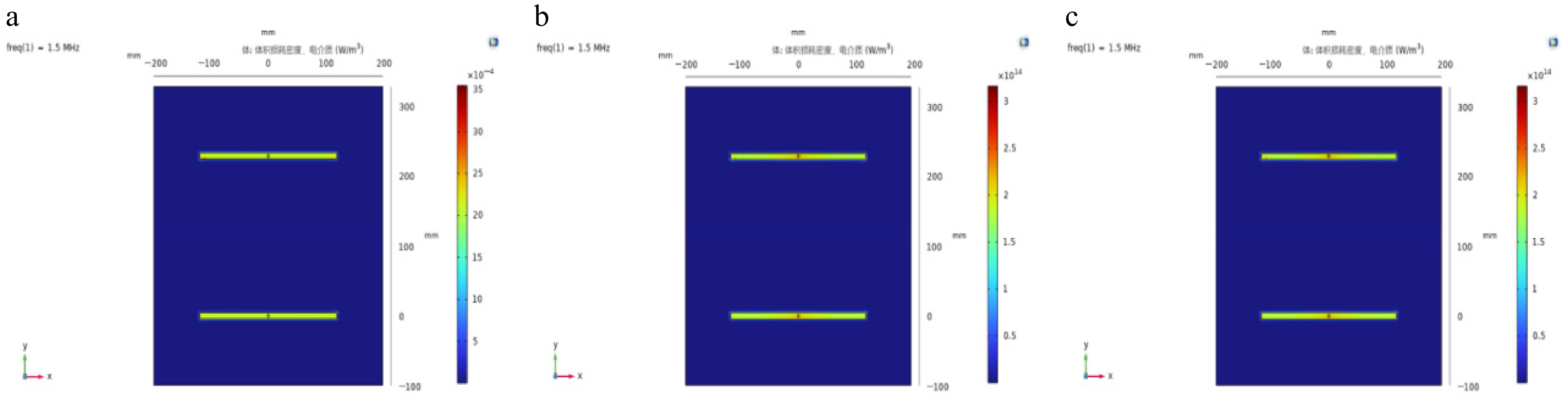
Figure 5.
Power loss density distribution of different typical dielectric materials. (a) Tempered glass. (b) Silicon carbide. (c) Alumina ceramics.
In general, alumina ceramics can be chosen as the dielectric material for electric field coupling mechanisms to achieve higher mutual capacitance and coupling coefficient, and lower power loss of the coupling mechanism.
-
The bilateral LC type resonant topology is widely used in ECPT systems due to its advantages of easy implementation, few compensation components, strong reliability, and good filtering characteristics, and can also be applied to low to medium-power applications. The typical network topology structure is shown in Fig. 6[10].
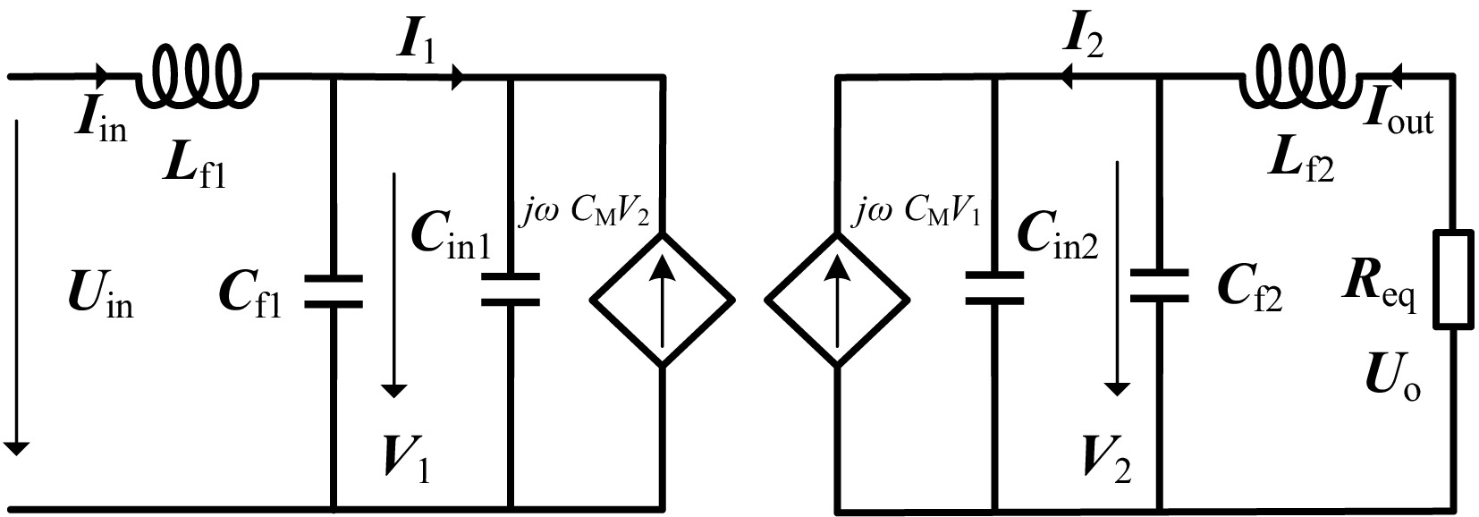
Figure 6.
Bilateral LC type resonant topology under π equivalent model.
This type of topology can achieve a constant output current. In addition, the load current is inversely proportional to the coupling capacitance. Therefore, changes in coupling parameters can affect the output current of the system. The equivalent self-capacitances are expressed as C1= Cin1 + Cf1 and C2 = Cin2 + Cf2[11].
Instead of impedances, admittances are used in the analysis, which are defined in Table 3[11].
Table 3. Admittances of the circuit components.
Parameter Expression Parameter Expression YL1 $ \dfrac{1}{j\omega {L}_{1}} $ YL2 $ \dfrac{1}{j\omega {L}_{2}} $ YC1 $ j\omega {C}_{1} $ YC2 $ j\omega {C}_{2} $ Y1 $ j\omega {C}_{1}+\dfrac{1}{j\omega {L}_{1}} $ Y2 $ j\omega {C}_{2}+\dfrac{1}{j\omega {L}_{2}} $ YM $ j\omega {C}_{{\mathrm{M}}} $ YRL $ \dfrac{1}{{R}_{{\mathrm{L}}}} $ Write the KVL and KCL equation for the system as follows:
$ \begin{cases} {U}_{{\mathrm{in}}}=j\omega {L}_{{\mathrm{f1}}}{I}_{{\mathrm{in}}}+\dfrac{1}{j\omega {C}_{{\mathrm{f1}}}}\left({I}_{{\mathrm{in}}}-{I}_{1}\right)\\ {U}_{{\mathrm{o}}}=j\omega {L}_{{\mathrm{f2}}}{I}_{{\mathrm{out}}}+\dfrac{1}{j\omega {C}_{{\mathrm{f}}2}}\left({I}_{{\mathrm{out}}}-{I}_{2}\right)\\ {V}_{1}=\dfrac{1}{j\omega {C}_{{\mathrm{f}}1}}\left({I}_{{\mathrm{in}}}-{I}_{1}\right)\\ {V}_{2}=\dfrac{1}{j\omega {C}_{{\mathrm{f}}2}}\left({I}_{{\mathrm{out}}}-{I}_{2}\right)\\ \end{cases} $ (2) $ \begin{cases} {Y}_{{\mathrm{L}}1}\left({U}_{{\mathrm{in}}}-{V}_{1}\right)+{Y}_{{\mathrm{M}}}{V}_{2}={V}_{1}{Y}_{1}\\ {Y}_{{\mathrm{L}}2}\left({U}_{{\mathrm{o}}}-{V}_{2}\right)+{Y}_{{\mathrm{M}}}{V}_{1}={V}_{2}{Y}_{2}\\ {Y}_{{\mathrm{L}}2}\left({U}_{{\mathrm{o}}}-{V}_{2}\right)+{Y}_{{\mathrm{M}}}{V}_{2}=-{V}_{2}{Y}_{{\mathrm{RL}}}\\ \end{cases} $ (3) According to these equations, since a resistive load is used on the output side, the transconductance Gi is expressed as:
$ {G}_{{\mathrm{i}}}=\dfrac{{I}_{{\mathrm{out}}}}{{U}_{{\mathrm{in}}}}=\dfrac{{Y}_{{\mathrm{L1}}} \cdot {Y}_{{\mathrm{L2}}}\cdot{Y}_{{\mathrm{M}}}}{\left({Y}_{1}{Y}_{2}-Y_{{\mathrm{M}}}^{2}\right)+{Y}_{{\mathrm{L2}}}\cdot\left({Y}_{1}{Y}_{2}-Y_{{\mathrm{M}}}^{2}-{Y}_{1}{Y}_{{\mathrm{L}}2}\right)\cdot{R}_{{\mathrm{L}}}} $ (4) Equation (3) show that the current Iout relate to the admittances of the passive components and the load resistance RL[12]. The expressions will be used to analyze the system frequency properties, which result in constant–current (CC) working mode.
Using Eq. (3), the CC frequency is determined by taking dGi/dRL = 0, which results in:
$ {Y}_{1}{Y}_{2}-Y_{{\mathrm{M}}}^{2}-{Y}_{1}{Y}_{{\mathrm{L}}2}=0 $ (5) The CC frequency is given by:
$ {\omega }_{{\mathrm{c}}}=\dfrac{{\omega }_{1}}{\sqrt{1-k_{{\mathrm{c}}}^{2}}} $ (6) Due to the parallel connection of Cf1 and Cf2 on both sides of the equivalent π model, they can be equivalently simplified into two capacitors of size C1−CM and C2−CM, the corresponding structure is reflected in Fig. 7, where C1= Cin1 + Cf1 and C2 = Cin2 + Cf2.
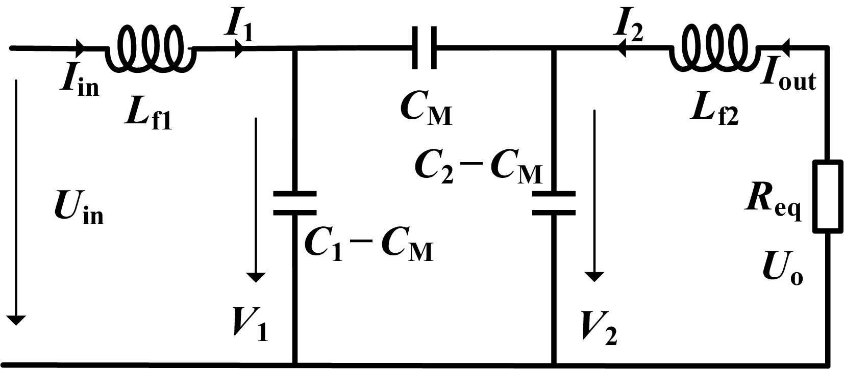
Figure 7.
Equivalent circuit of bilateral LC resonant network under π model.
In order to facilitate the analysis of the topology characteristics of bilateral LC compensation, the π model in the bilateral LC compensation topology can be transformed into a T model, as shown in Fig. 8.
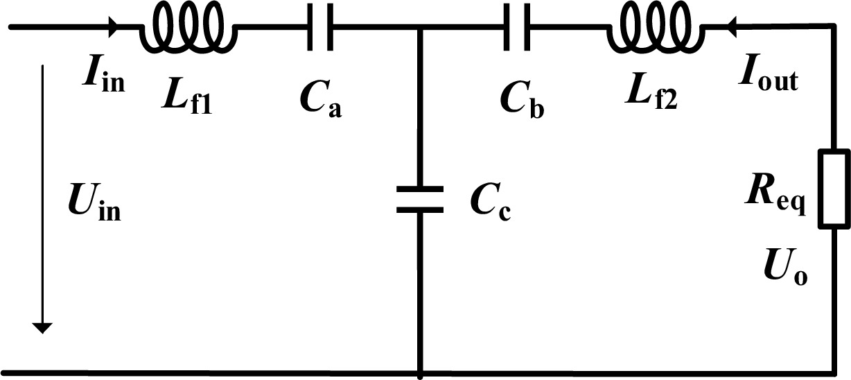
Figure 8.
Equivalent circuit of bilateral LC resonant network under T model.
By decomposing Lf1 and Lf2 into Lf11 + Lf12 and Lf21 + Lf22 as shown in Fig. 9, it is more convenient to analyze and solve the resonant angular frequency of the network, which is:
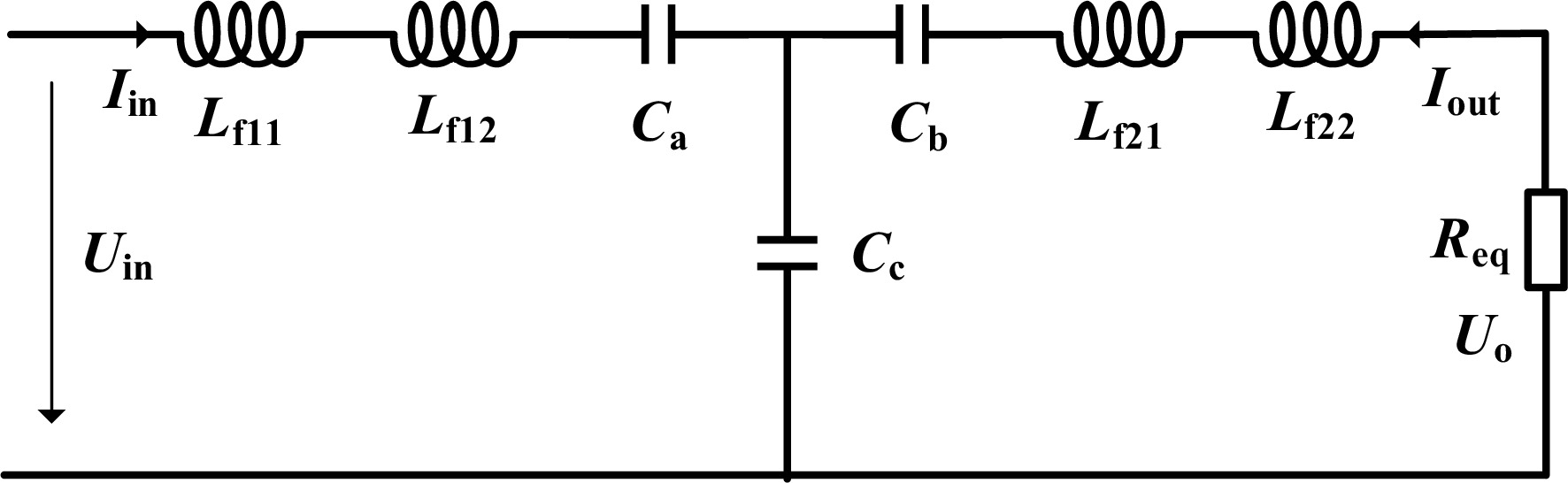
Figure 9.
Equivalent circuit of bilateral LC resonant network after inductor splitting.
$ \omega =\dfrac{1}{\sqrt{{L}_{{\mathrm{f}}12}{C}_{{\mathrm{a}}}}}=\dfrac{1}{\sqrt{{L}_{{\mathrm{f}}21}{C}_{{\mathrm{b}}}}} $ (7) The input resistance expression of the system is:
$ Z_{{\mathrm{in}}}=j \omega L_{{\mathrm{f}}1}+ \dfrac{1}{j\omega C_{\mathrm{a}}}+\dfrac{-\omega^2 L_{{\mathrm{f}}2}C_{\mathrm{b}} + j \omega R_{{\mathrm{eq}}}C_{\mathrm{b}} +1}{j\omega(-\omega^2 C_{\mathrm{b}}C_{\mathrm{c}}L_{{\mathrm{f}}2}+ j\omega C_{\mathrm{b}}C_{\mathrm{c}}R_{{\mathrm{eq}}}+C_{\mathrm{b}}+C_{\mathrm{c}})} $ (8) Based on the fundamental approximation method, the system circuit is analyzed. Taking into account the influence of reactive elements such as inductors and capacitors, as well as the equivalent series resistance of coupling units, the equivalent circuit diagram of the ECPT system based on a bilateral LC compensation network is shown in Fig. 10. The output of the inverter can be equivalent to an AC voltage source Vin, where Re represents the equivalent resistance of the full bridge rectifier and load resistor, with a value of 8RL/π2. Among them, RL1, RC1, RL2, and RC2 are the equivalent series resistances of the compensating elements, respectively. The coupling capacitance is represented by the equivalent series coupling capacitance Cs, where RCs is the equivalent series resistance of the coupling capacitance Cs, and its value is tanδ/(2πfCs), where tanδ is the tangent of the dielectric loss angle of the coupling capacitance Cs[13].
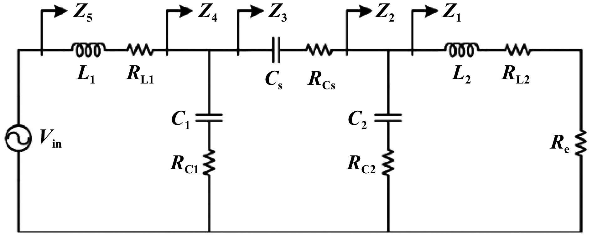
Figure 10.
Equivalent circuit of bilateral LC compensation ECPT system.
The effective value Vin of the fundamental wave of the inverter output voltage can be expressed as:
$ {V}_{{\mathrm{in}}}=\dfrac{2\sqrt{2}{V}_{{\mathrm{dc}}}}{\pi} $ (9) The amplitudes Vo and Io of the input voltage and current of the rectifier can be expressed as:
$ \left\{\begin{aligned}{V}_{\mathrm{o}}&=2\sqrt{2}{V}_{{\mathrm{RL}}}/{\pi} \\ {I}_{{{\mathrm{o}}}}&={\pi} \sqrt{2}{I}_{{\mathrm{RL}}}/4\\ \end{aligned}\right\} $ (10) -
Figure 11 is a prototype of the UAV electric field-coupled wireless charging system that was constructed. The system adopts a double-sided LC compensation topology to achieve constant-current resonant tuning. It primarily consists of a DC power supply, a full-bridge inverter, a coupling structure with its associated compensation network, a rectifier circuit, and an aluminum-case resistive load. The system is designed to operate at a rated frequency of 1.5 MHz. The structural block diagram of the experimental setup is shown in Fig. 12.
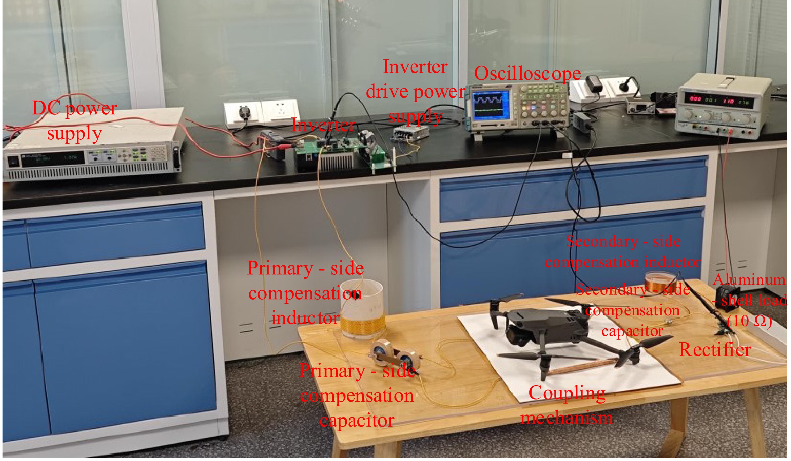
Figure 11.
Experimental prototype of the wireless charging system.
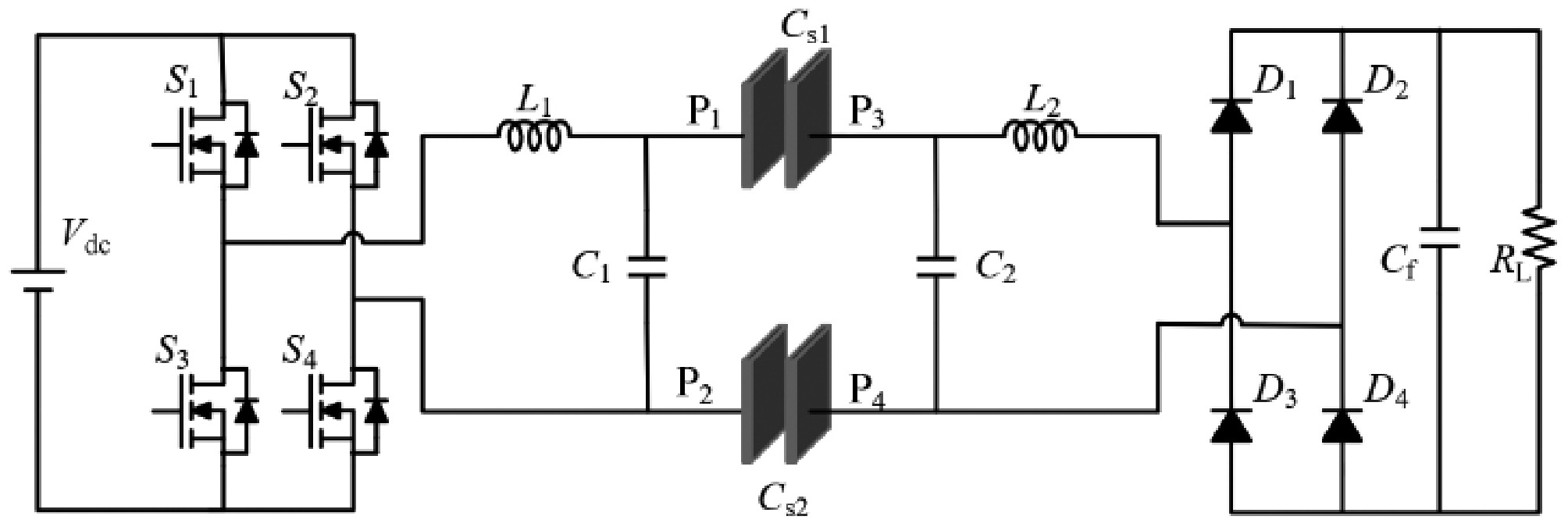
Figure 12.
Block diagram of the experimental system architecture.
Both the transmitting and receiving electrodes in the coupling structure are made of copper plates. To reduce the weight of the receiving end and enhance its power density, the receiving electrodes were implemented by copper cladding on the bottom of the UAV's support frame, while the dielectric layer remained aluminum oxide ceramic. The capacitors in the compensation topology are disk-type ceramic capacitors; in later experimental refinements, the secondary-side capacitors will be replaced with TDK surface-mount capacitors. The inductors are wound using Litz wire to minimize AC resistance and associated losses.
The rectifier adopts a full-bridge topology composed of four diodes connected in a bridge configuration, enabling the conversion of AC signals into unidirectional pulsating DC. This structure ensures continuous output current with consistent polarity. The load consists of a 10 Ω aluminum-case resistive load. The detailed system parameters are listed in Table 4.
Table 4. System parameters.
Parameter Value Parameter Value f (MHz) 1.5 Vdc (V) 50 L1 (μH) 30.7 Cex1 (pF) 330 L2 (μH) 30.7 Cex2 (pF) 330 CM (pF) 33.1 Cin1 (pF) 39.1 Kc 0.0898 Cin2 (pF) 39.1 RL (Ω) 10–50 After completing the construction of the experimental setup, individual subsystems such as the inverter and rectifier were sequentially debugged. With the coupling structure parameters fixed, precise tuning of the capacitance and inductance in the compensation topology was conducted to maximize system efficiency and achieve the target rated output power of 200 W. Given the stable performance characteristics of disk ceramic capacitors, their capacitance values were treated as fixed parameters. In contrast, the inductors—wound using Litz wire—allowed for continuous adjustment of inductance by manually varying the number of turns. Therefore, the initial tuning strategy was established by fixing the capacitance values and dynamically adjusting the inductance to meet the system design requirements.
Figure 13 presents the measured waveforms of the system during normal operation, including the inverter bridge output voltage (CH1), inverter bridge output current (CH2), and rectifier output voltage (CH3). It can be observed that CH2 lags slightly behind CH1, which facilitates soft-switching of the inverter switches, thereby contributing to improved system efficiency. Under these conditions—with an operating frequency of 1.5 MHz and a load resistance of 50 Ω—the system achieves an output power of 200 W and a power conversion efficiency of 87%. A dynamic UAV battery pack was also tested under 200 W pulse loads; efficiency remained within 1% of the resistive-load value.
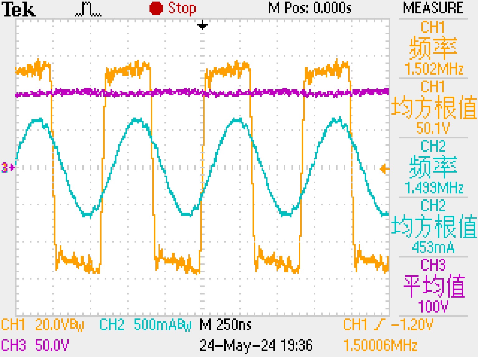
Figure 13.
System waveforms at R = 50 Ω (output power: 200 W, DC-DC efficiency: 87%).
To simulate practical UAV wireless charging scenarios, the load resistance (aluminum-housed resistor) was gradually adjusted to 40, 30, 20, and 10 Ω. The experimental waveform corresponding to the 10 Ω load condition is shown in Fig. 14. When the system output power stabilized at approximately 200 W, the measured power transfer efficiency reached 84.2%.
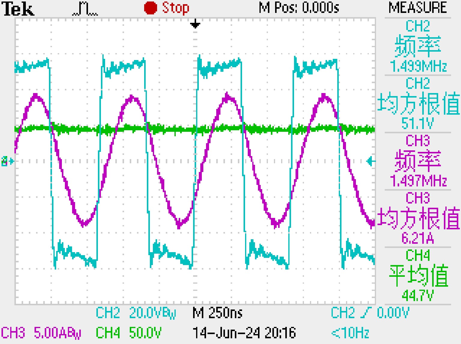
Figure 14.
System waveforms at R = 10 Ω (output power: 200 W, DC-DC efficiency: 84.2%).
As shown in Fig. 15, the variation of the system efficiency under different dielectric materials and load conditions is kept within 4% at a constant output power of 200 W. This shows that the system maintains a relatively stable efficiency at the same power level, and the average efficiency of the system with alumina ceramic as the medium is the highest among different materials. A slight decrease in efficiency was observed as the load resistance decreased from 50 to 10 Ω. This behavior is attributed to an increase in the output current required to maintain constant power at lower resistances, resulting in higher conduction losses between the resistances within the system components. This efficiency drop is caused by load-induced current changes, not by defects in the system design.
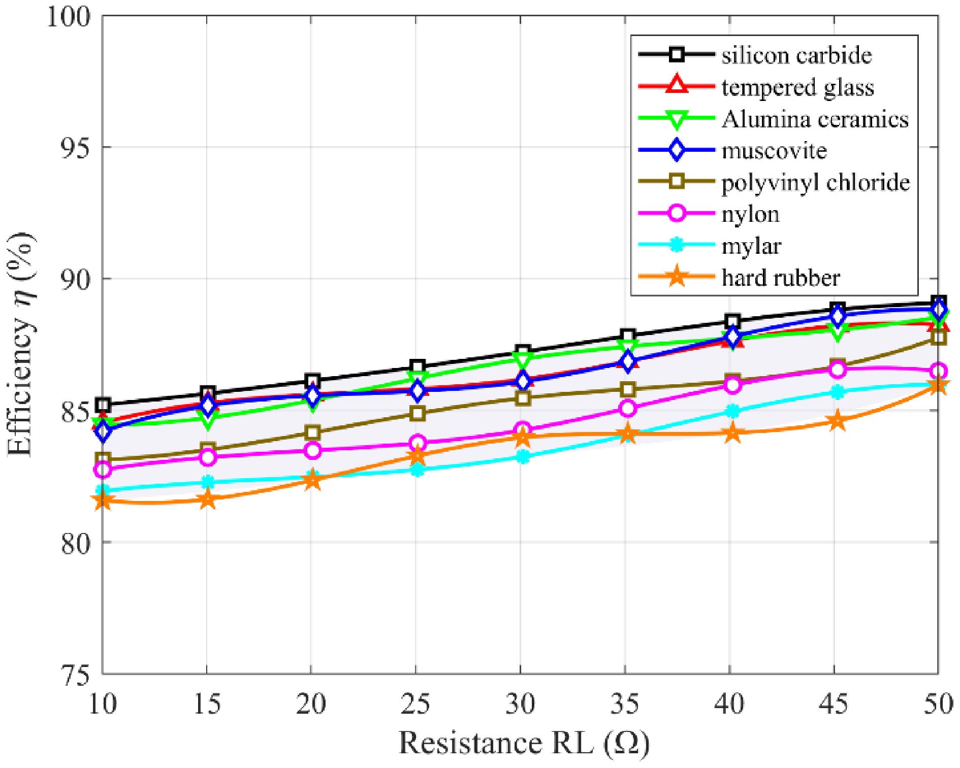
Figure 15.
Variation of DC-DC efficiency under different load resistances.
As summarized in Table 5, compared with other UAV electric field-coupled wireless power transfer systems, the proposed system demonstrates a significant advantage by achieving both high charging power and high efficiency simultaneously. This highlights its strong potential and practical value for applications in the field of UAV wireless charging.
-
The present study explores the design and implementation of a high-frequency, high-efficiency ECPT system for UAV wireless charging, addressing key limitations in existing literature that often overlook the integration of lightweight materials and high power density in practical UAV applications. By employing a dual-sided LC compensation topology and selecting alumina ceramics as the dielectric, the system achieves high efficiency with minimized loss and compact structure. Importantly, the findings challenge the assumption that electric field-based power transfer is limited to low-power use, demonstrating its viability for higher-power UAV scenarios. The material analysis further reveals that the imaginary part of the dielectric constant significantly impacts power loss, especially at MHz-level frequencies, offering a new lens for dielectric material selection in future designs.
Despite its strong performance, the system exhibits a relatively low coupling coefficient (Kc = 0.0898), indicating opportunities for optimization in coupling geometry through simulation or intelligent design tools. Moreover, real-world conditions such as UAV misalignment, hovering instability, and dynamic load variations highlight the need for adaptive impedance control and further robustness. As such, this work provides not only a high-performance ECPT prototype but also a valuable foundation for the development of next-generation UAV charging systems, contributing both practically and conceptually to the advancement of autonomous aerial energy replenishment technologies.
-
This paper addressed the critical limitations of low efficiency and limited power in conventional UAV charging by developing a novel wireless power transfer system based on Electric Field Coupled Power Transfer technology. The proposed solution integrates a lightweight, tightly-coupled quadrupole plate structure with an optimized dual-sided LC compensation topology, enabling highly efficient power transfer at a high operating frequency of 1.5 MHz. Key innovations include the strategic use of aluminum oxide ceramic as a dielectric to minimize power loss and the enhancement of mutual capacitance and coupling coefficient through detailed analysis of coupling capacitance and dielectric properties. Experimental validation confirms the system's high performance: it achieves stable constant-current output with a peak power conversion efficiency of 87% and delivers a rated power of 200 W. These results demonstrate the feasibility and practicality of this ECPT system for UAV applications. Consequently, the system is extensible to other autonomous platforms—ground robots, and marine drones—where weight, volume, and safety constraints are similarly severe. The introduced ceramic-dielectric methodology and PT-symmetric compensation strategy furnish a template for MHz-level, multi-kilowatt systems in logistics drones, agricultural UAV swarms, and urban air-mobility vehicles. Moreover, the coupling-coefficient optimization pipeline and misalignment-tolerant control algorithms developed herein can be seamlessly imported into inductive or hybrid WPT systems, accelerating the convergence toward universal, contact-less charging infrastructures for smart cities and industry.
-
The authors confirm their contributions to the paper as follows: study conception and design: Chen Q, Xiao J, Chen S; data collection: Wu X, Jiang Q, Lu X; analysis and interpretation of results: Chen Q, Jiang Q; draft manuscript preparation: Lu X. All authors reviewed the results and approved the final version of the manuscript.
-
All data included in this study are available upon request by contact with the corresponding author.
-
The project receives support from the Key Technology Project of China Southern Power Grid Guangxi Electric Power Co., Ltd. Research on Development and Application of Distribution Network Inspection UAV Based on Electric Field Coupling Wireless Charging Technology (Grant No. 02150026050243).
-
The authors declare that they have no conflict of interest.
- Copyright: © 2026 by the author(s). Published by Maximum Academic Press, Fayetteville, GA. This article is an open access article distributed under Creative Commons Attribution License (CC BY 4.0), visit https://creativecommons.org/licenses/by/4.0/.
-
About this article
Cite this article
Chen Q, Xiao J, Chen S, Wu X, Jiang Q, et al. 2026. Design and analysis of CPT system unmanned aerial vehicle applications. Wireless Power Transfer 13: e010 doi: 10.48130/wpt-0025-0037 

Design and analysis of CPT system unmanned aerial vehicle applications
- Received: 27 July 2025
- Revised: 08 August 2025
- Accepted: 19 August 2025
- Published online: 23 April 2026
Abstract: To address the limitations of conventional UAV charging methods, this paper presented a lightweight, high-efficiency, and high-power-density wireless charging system for unmanned aerial vehicles (UAVs) based on electric field coupling power transfer (ECPT) technology, which provides an effective solution that integrates high power, high efficiency, and low loss, offering significant engineering value for future UAV wireless charging systems. The system adopts a dual-sided LC compensation topology combined with a tightly coupled quadrupole plate structure. By analyzing the resonant characteristics and deriving optimal design parameters, efficient power transfer at a high operating frequency of 1.5 MHz is achieved. To improve the transfer efficiency, aluminum oxide ceramic is employed as the dielectric material, while analysis of the coupling capacitance and dielectric properties is presented to improve the mutual capacitance and coupling coefficient. Experimental results demonstrate that the proposed ECPT system achieves stable constant–current output with a maximum power conversion efficiency of 87%. A prototype successfully delivers a rated output power of 200 W, validating the system's feasibility and practicality for UAV applications.