-
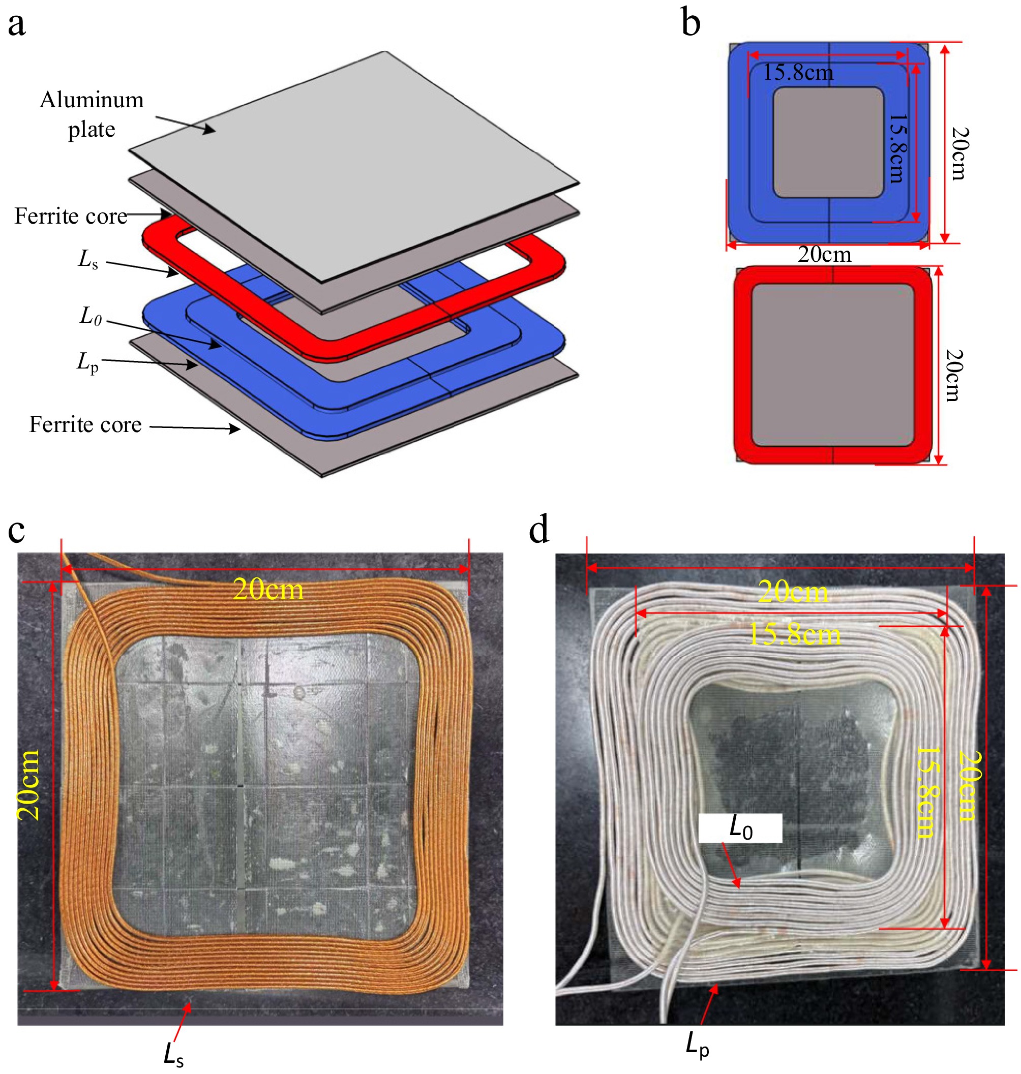
Figure 1.
The magnetic coupling structure: (a) Overview, (b) specific details, (c) picture of Ls, and (d) picture of Lp and L0.
-
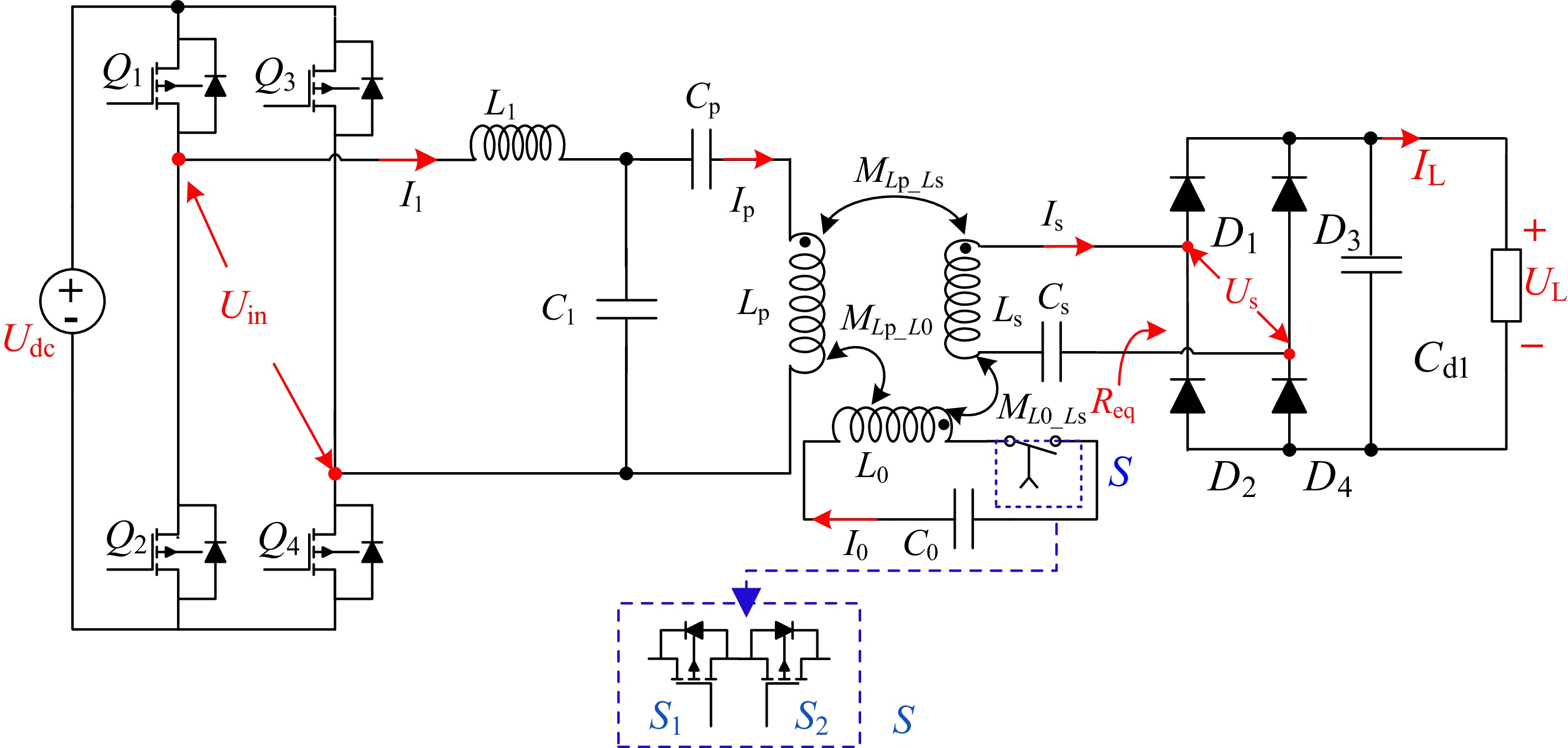
Figure 2.
Circuit diagram of the proposed WPT system.
-
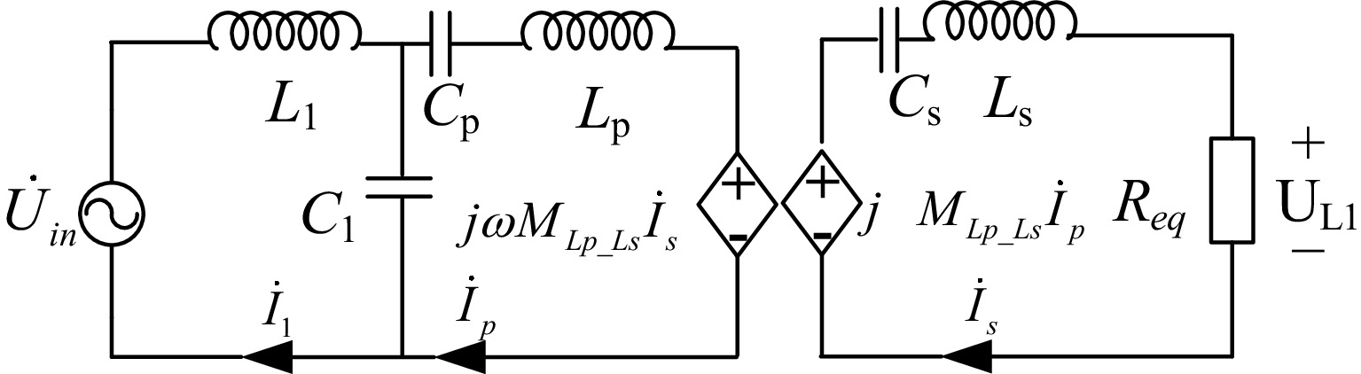
Figure 3.
Equivalent circuit with the LCC-S topology.
-
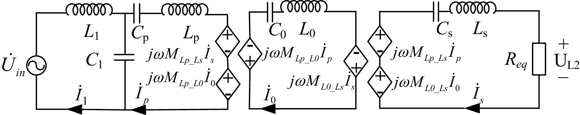
Figure 4.
Equivalent circuit with the LCC-S-S topology.
-
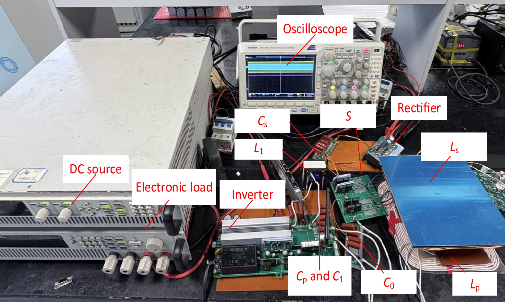
Figure 5.
Picture of the experimental setup.
-
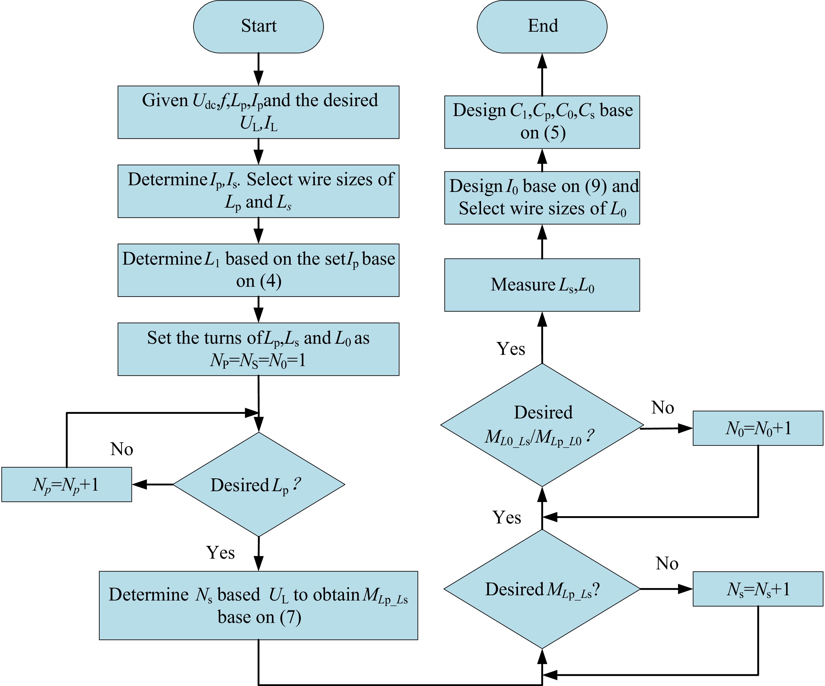
Figure 6.
Design flowchart of the system's parameters.
-
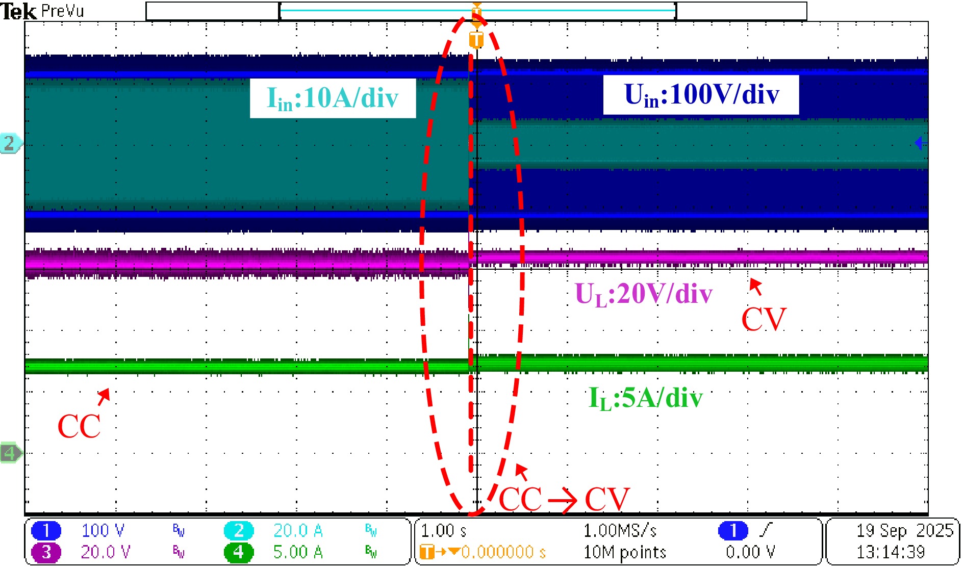
Figure 7.
Dynamic response of the system switching from CV (LCC-S) to CC (LCC-S-S) mode.
-
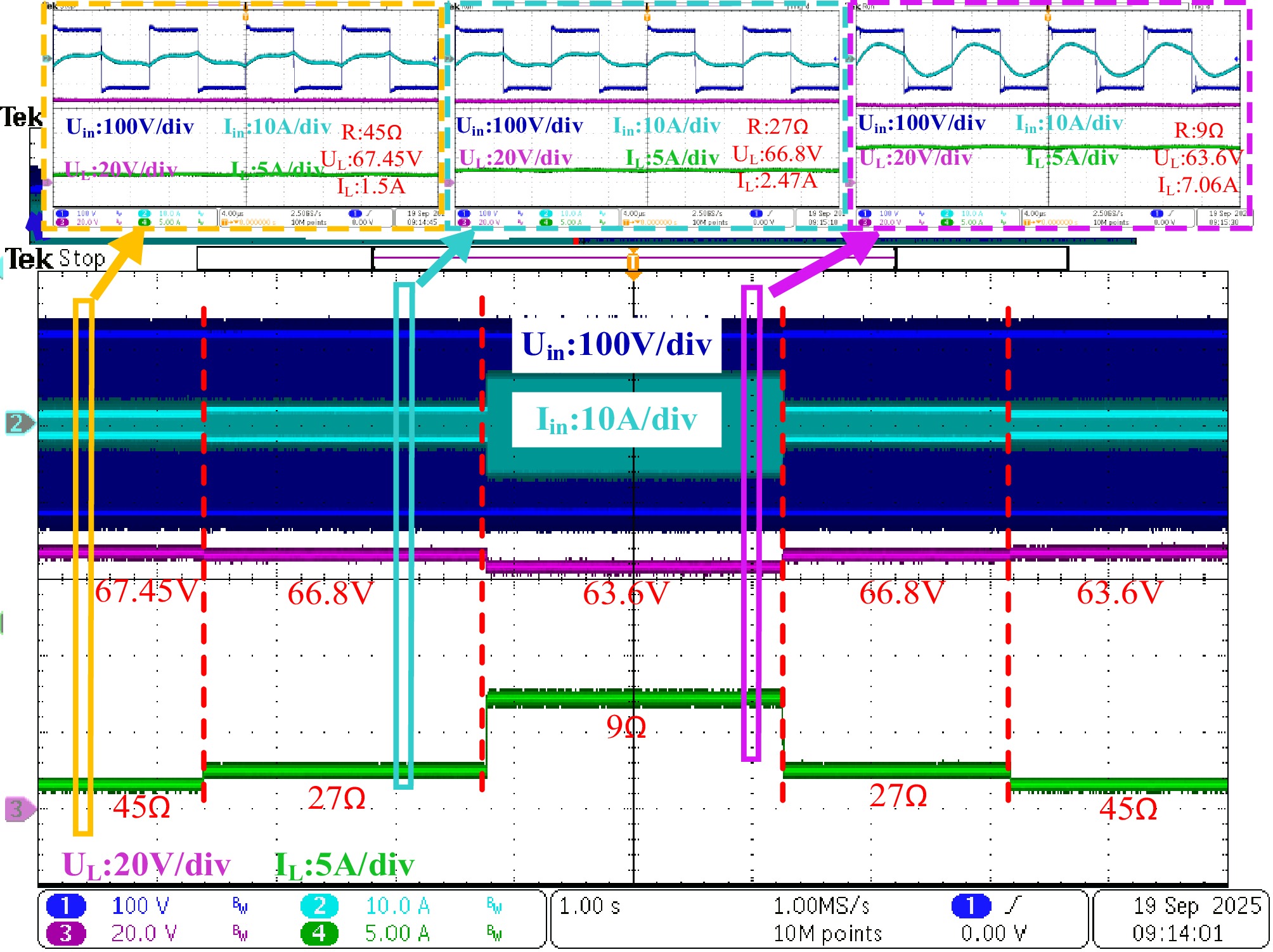
Figure 8.
Dynamic response of the system in CV (LCC-S) mode.
-
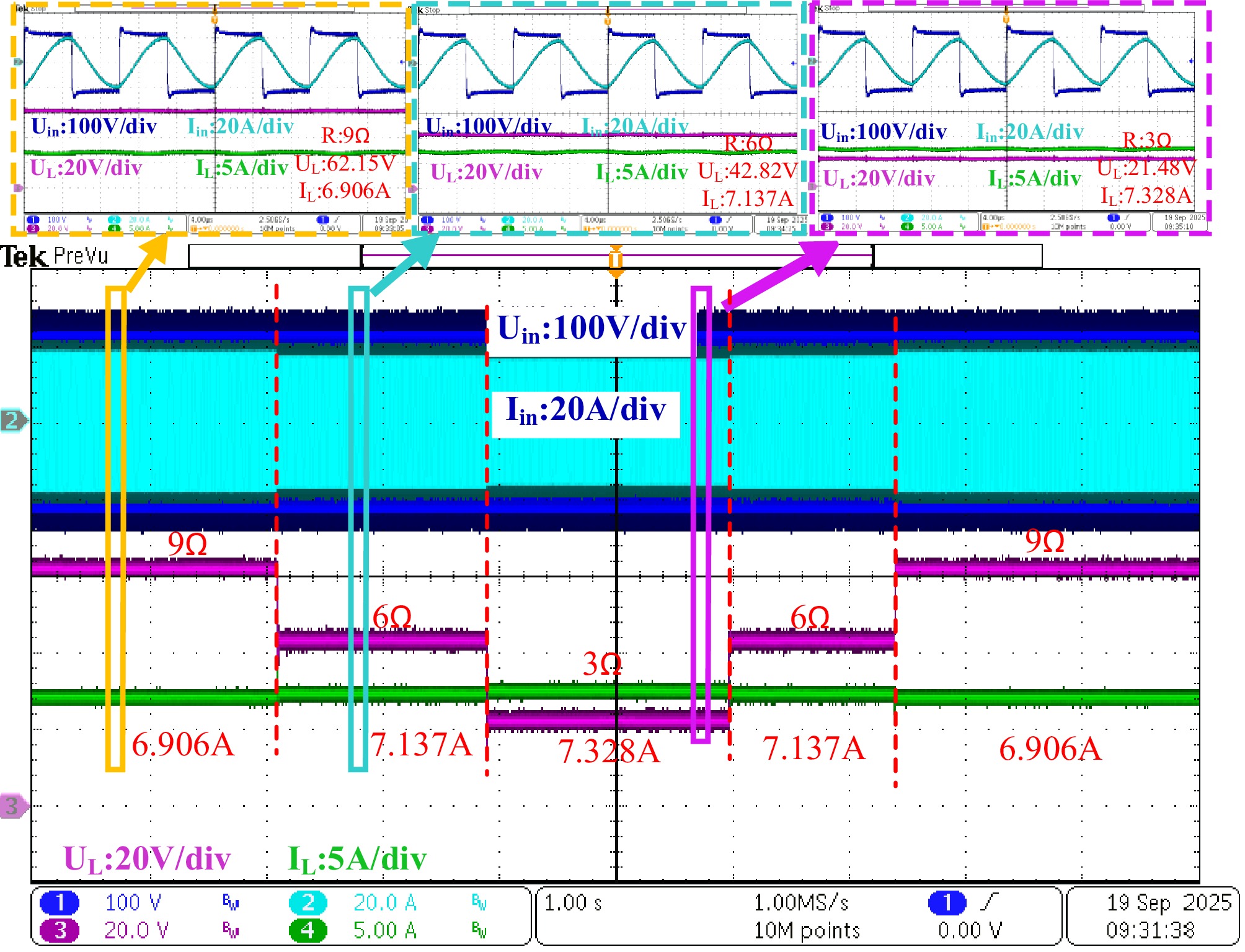
Figure 9.
Dynamic response of the system in CC (LCC-S-S) mode.
-
Lp L0 Ls L1 Cp 87.5 μH 24.5 μH 84.5 μH 45 μH 61.8 nF C0 C1 Cs MLp_Ls MLp_L0 103.4 nF 46.5 nF 29.94 nF 32.5 μH 38.1 μH ML0_Ls UL IL Udc f 15.58 μH 63 V 7 A 120 V 100 kHz Np N0 Ns d 15 8 12 5 cm Table 1.
The system's parameters.
-
Ref. Method Control complexity Hardware Efficiency Main limitation and characteristic [15] Frequency control High (needs communication systems) Low (two-coil) 96.5% Risk of bifurcation and instability [16] Phase shift High (synching required) Low (two-coil) 93.59% Reactive circulating current [17] PDM High (complex system) Low (three-coil) 91.55% High output ripple and acoustic noise [18] Clamp coil Low (passive) High (three-coil) 90.2% Complex cross-coupling issues [19] Hybrid switch Medium (multi-switch) Very high 94.5% High cost and low reliability Proposed LCC-S-S Very low (open-loop) Moderate 89.6% Optimal balance: Robust and cost-effective Table 2.
Comparison between this paper and other studies.
Figures
(9)
Tables
(2)