


-
Advances in wireless recharging have enabled active implantable medical devices to be recharged across the skin using a transcutaneous energy transfer system or TETS[1,2]. Devices like pacemakers, and deep brain stimulators employ such techniques in their advanced models which increase the patients comfort by enhancing the battery replacement intervals[3]. Various technologies have been tried so far which includes inductive[4], capacitive[5], ultrasound[6], blue tooth based[7], and resonance based[8]. Of the various technologies, resonance based inductive power transfer is found to be very promising with its high power capability, long-distance range, and higher efficiencies achieved[9,10]. Efforts are made to deploy the technology with higher power capability in high power consuming implantable medical devices such as ventricular assist devices (VAD), total artificial hearts (TAH)[11], etc. to reduce the risk of infection around the site of percutaneous wire connection[12]. The major challenge in the reliable use of this technology is the control of energy transfer during various situations like miss-alignment, skin thickening, dynamic movements, etc.[13]. Unlike conventional wireless recharging, TETS operate in a dynamic body environment, where the patient may change posture, sit, stand, run, and breathing[14,15]. These dynamic movements change the operating characteristics and the system operates in sub optimal conditions with less efficiency and voltage gain[14−16]. The lesser efficiency leads to more power loss and an increase in the temperature of the tissue surrounding the TETS[17,18].
To operate the system efficiently during dynamic situations, a control system[19] is required to adjust the parameters such as frequency, resonating capacitor, etc. By varying the frequency or impedance, resonance may be achieved at the required coupling coefficient and maximum power can be obtained[20,21]. Many approaches have been studied to provide a proper control system for the TETS. A transcutaneous energy transfer (TET) system[17] with an auto-tuning mechanism has been developed to power implantable devices such as artificial hearts, defibrillators, and electrical stimulators. In the auto-tuning method, the phase difference between the primary coil voltage and the current has been maintained as zero to obtain the maximum power transfer conditions. Efficiency in the range of 60% to 80% has been obtained with a coil-to-coil separation in a range of 3−15 mm.
It has been shown that voltage regulation is achieved by using a transcutaneous infrared feedback control loop operating on an 890 nanometer (nm) wavelength[22]. In vitro testing of the system developed has shown that output voltage can be maintained to within 0.2 V of nominal (14.5 V) for delivered powers up to 50 watts (W) and coil separations of between 3 and 10 mm. Power transfer efficiencies were determined to be 68% to 72% over the tested range of coil separations and output currents from 1.5 to 3.6 amperes. The major disadvantage is the substantial reduction in voltage regulation when the coil misaligns. Also, a TET system with a closed loop frequency-based power regulation method is presented to deliver the right amount of power to the load under variable coupling conditions[23]. In another study, a switched capacitor control method is deployed to control the system[24]. The system is capable of regulating power for axially aligned separations of up to 10 mm and lateral displacements of up to 20 mm when delivering 10 W of power. A bank of capacitors is switched to achieve the same. Even though the system could deliver the required amount of power, it has bulky capacitors being switched with mosfets for regulating the power. Additional electronic circuits and triggering circuits were required for the purpose. An RF communication channel is used for the control which also adds electronic circuitry in the implanted side. The requirement of a feedback signal for changing the capacitance value is improved in which a voltage-controlled capacitance using concepts of the negative impedance converter and capacitance multiplier is reported[25]. The phase angle between the input voltage and current is used as the error signal to control the variable capacitance and keep the output power at the operating point. However, the application of the system is limited to lower power ranges and is not suitable for operating artificial hearts. A better method is reported for controlling the output voltage of a pickup in an inductive power transfer (IPT) system without any additional form of communication for feedback from the pickup to the power supply[26,27]. The method comprises the steps of deriving an estimate of the output voltage of the pickup from the voltage across the primary conductive path, and adjusting the current in the primary conductive path so that the estimated pickup output voltage matches a required pickup output voltage. An estimate of the pickup output voltage is derived from the magnitude and phase angle of the voltage in the primary conductive path. A space-frequency approach[28] for controlling the power transfer during misalignments in which dependency of coupling coefficient on the system geometry, to determine the optimal operating frequency for the specified relative position of the coils is proposed.
In the above-mentioned techniques, regulation of the output voltage and higher efficiencies are obtained by feeding back the output voltage through electronic circuitry to the primary side and thereby controlling it through conventional means. In the case of LVAD, the secondary coil is implanted within the skin and the secondary circuits are part of the complex LVAD control systems. Any amount of excess electrical energy requirement affects the LVAD battery life and thus needs to be preserved. The feedback electronics consumes energy for its operation and it has to be taken from the reserved internal battery. It will be highly desirable not to consume any energy from this internal battery and thus a better method of control is envisaged. In other techniques where the system parameter is controlled from the primary side, the speed of operation and the fine adjustment cannot be obtained. The variations in coil alignment shall induce a large fluctuation in the power output. These power fluctuations seriously affect the performance of life-saving devices like artificial hearts. Similarly, the system should have automatic control of its performance during skin thickness variations, person-to-person variations with the maximum power transfer, etc. Automatic control of the TETS system is needed to fulfill the need for artificial heart performance during physical activity.
Thus, a better control strategy where maximum power transfer can be achieved without having any feedback loop from the secondary side as well as switching of passive components will be highly desirable for practical use of the TETS system for powering artificial hearts and ventricular assist devices. Hence novel methods of automatic control of the power during dynamic situations like skin thickness variation, posture variations, breathing, physical activity, etc. need to be investigated.
In this paper, a method for automatically controlling the maximum power transfer in a transcutaneous energy transfer system for powering artificial hearts and VADs without the use of any feedback signals from the implanted secondary side is presented. The automatic tuning shall adjust the frequency of operation of the resonant converter to operate at the optimum conditions during dynamic situations skin thickness variation, posture variations, breathing, physical activity, etc. The system architecture, and methodology for automatic tuning is provided in Materials and methods session. The testing and analysis of the system as well as discussion on the effect of the automatic tuning method for coil-to-coil misalignment, separation gap, and load variations is provided in Results session.
-
Figure 1a, shows the architecture of a transcutaneous energy transfer system consisting of a resonant-based inductive power transfer system. It consists of a primary side transmitter circuitry which is kept over the skin, and a secondary side receiver circuitry kept subcutaneously under the tissue within the body. The primary side transmitter circuitry consists of a spiral wound pancake coil, a resonating capacitor, a full bridge resonant circuit, and a controller separated by a ferrite sheet. The spiral wound coil is connected in series with the resonating capacitor which in turn is connected to the resonant full bridge converter. The primary circuit consists of a resonant full bridge circuit with a 40 μH inductor and 27 nF capacitor in series. A spiral pancake coil is made up of 400 turns of SWG48 litz wire with an overall diameter of 80 mm and acts as the transmitting coil. A 27 nF capacitor is used as the resonant capacitor with a resonating frequency of 150 kHz.
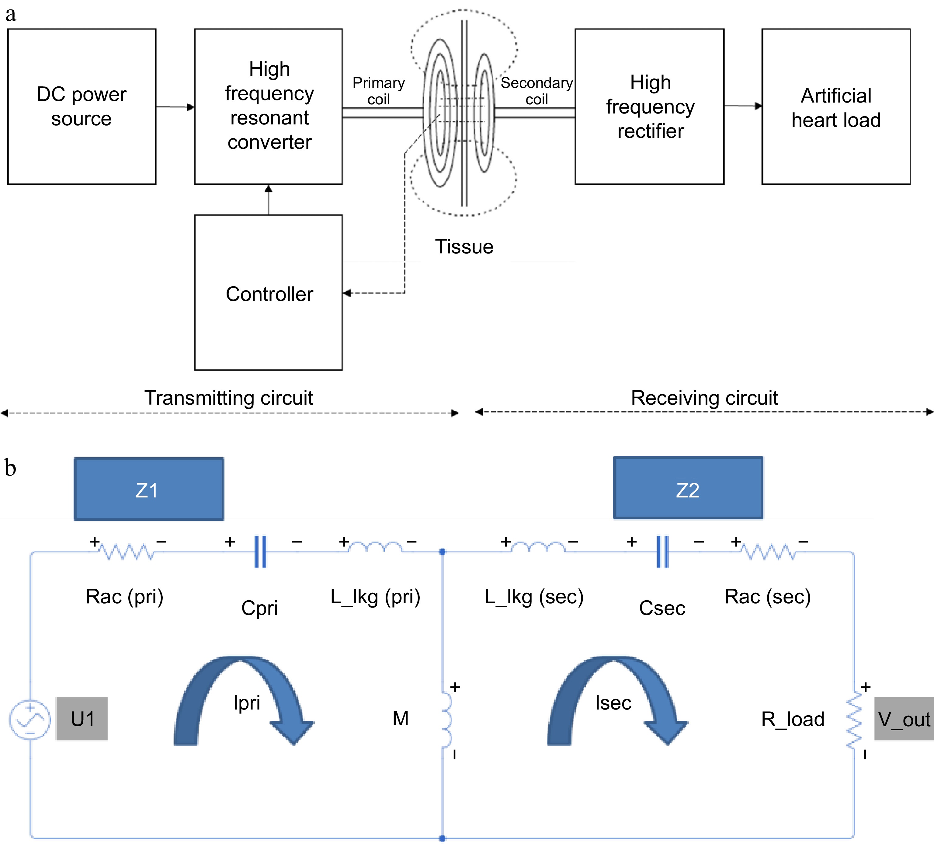
Figure 1.
(a) TETS architecture. (b) Lumped parameter model.
The secondary side receiver circuitry of the system consists of a series connected spiral wound pancake type receiving coil and a resonant capacitor connected to a full bridge resonant bridge rectifier. The receiving coil is made up of 400 turns of SWG48 litz wire with an overall diameter of 80 mm connected in series with 27 nF capacitor and fed to a full bridge rectifier. The output of the rectifier is filtered using a capacitor and connected to a resistive load or to the LVAD controller for studying the performance. The VAD under consideration operates at a voltage of 15 V with a power rating of 10 W. Thus, the controller is considered as a resistive load varying from 10 to 40 ohms. For simplicity in understanding, a lumped model of the two-coil transcutaneous energy transfer system is developed as shown in Fig. 1b. The lumped model consists of a first loop made of the equivalent AC resistance, capacitance, and leakage inductance of the primary coil coupled to a secondary loop through mutual inductance. The secondary loop consists of AC resistance, capacitance, and leakage inductance of the secondary coil connected to a load resistance.
When the primary side transmitter circuit is powered from a battery or a suitable direct current source, the full bridge resonant circuit generates a high frequency square wave pulse to pass through the series connected spiral coil and resonant capacitor. The combination of spiral coil and the capacitor produces a sinusoidal voltage across the spiral coil inductor when exited with the square wave input. The magnitude of the sinusoidal voltage varies with the frequency and becomes maximum at a characteristic frequency called resonant frequency, which in turn is a parameter depending on the inductance of the transmitting spiral coil, primary side capacitor and the coefficient of coupling between the primary side transmitting coil and the secondary side receiving coil. The sinusoidal voltage in the transmitting spiral coil produces an alternating electromagnetic field around the primary side coil. The electromagnetic field interacts with the secondary side receiving coil and induces a voltage in it due to Faraday's laws of electromagnetic induction. The generation of the voltage across the secondary side spiral coil is made to resonate with the presence of a capacitor connected in series with the secondary coil. At resonance, maximum energy is transferred from the primary side to the secondary side. The alternating voltage produced across the series connected to the secondary side spiral coil and the capacitor is fed to the full bridge rectifier, which in turn converts it to a direct voltage. The direct voltage is then filtered to remove all ripples and is provided to charge the battery of an implanted device or directly power the implanted artificial heart.
TETS hardware
-
To study the performance, the hardware of the TETS to deliver power up to 30 W is developed. The hardware circuit consists of a resonant converter, primary coil, secondary coil, and a high frequency rectifier connected to a resistance load as shown in Fig. 2. A rheostat with a resistance variation from 10 to 40 ohms is considered as the load. The inductance and capacitance of the transmitting and receiving side are selected to get a design frequency of 150 kHz. During operation, the TETS may encounter various dynamic situations as shown in Fig. 3. Figure 3a shows the variation in the axial gap due to tissue thickness where the center to center distance between the coils changes. In Fig. 3b, lateral shift during a coil replacement activity is shown. In Fig. 3c, orientation of the coil is changed during a posture variation such as sitting or lying in bed. The orientation angle 'θ' will be changing during the posture change. In Fig. 3d, a combination of activity including respiration and movement is shown. In this situation, the orientation angle 'θ' will be a function of time. In addition to the physical changes happening on the coil, the load current also varies with respect to the operating nature of the medical device.
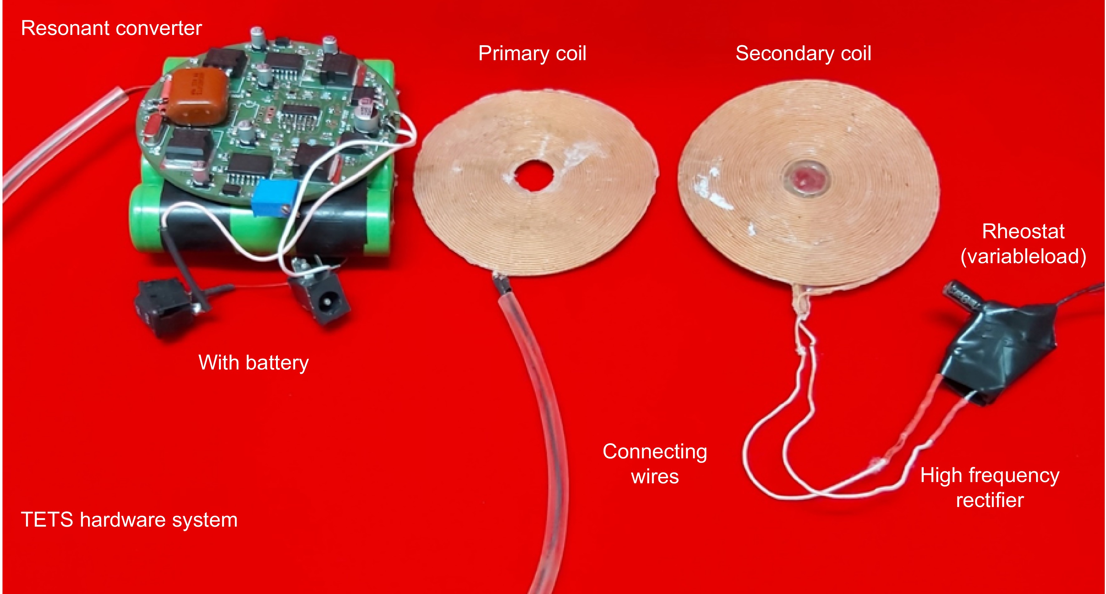
Figure 2.
TETS hardware.
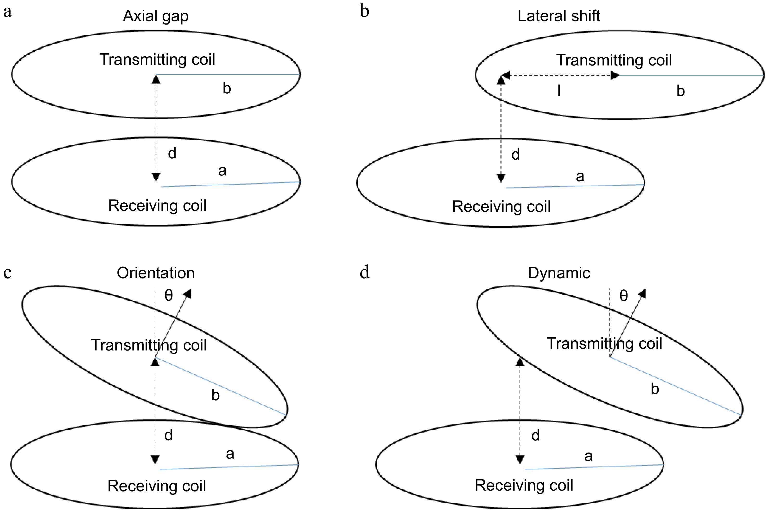
Figure 3.
TETS dynamic operating situations. (a) Varying skin thickness; (b) Replacement; (c) Posture variations; (d) Respiration and movements.
To understand the behavior of the TETS under these dynamic situations, frequency response, efficiency, voltage gain, and power output of the system are studied. The study includes varying the environment parameters suitable for most of the active implanted medical devices in the power range of a few watts to tens of watts as required by the artificial heart as given below:
• Load resistance variation between 10 to 40 ohms;
• Axial gap variation between 0 to 20 mm;
• Lateral shift variation between 0 to 20 mm.
A suitable jig is fabricated to fix the coils and make adjustments in the axial gap, lateral shift, and orientation. The TETS hardware is supplied with a 15 V power supply. Hence for the load resistance variations under study, a current variation in the range of 0.375 to 1.5 A is considered. A less load current condition is considered for load resistance variation in the range of 25 to 40 ohms, whereas a high load current condition is considered for load resistance variation between 10 to 25 ohms. The ventricular assist devices and total artificial heart may be operating at a high load current condition, where the load current varies between 0.75 and >1.5 A. However, small power active implantable medical devices which need to charge the internal batteries need only 200 to 500 mA of current. So the analysis of the TETS covers the entire spectrum of current demanded by the implantable medical devices.
Dynamic response with fixed frequency control
-
To analyze the dynamic response of the TETS without any control action, axial gap, lateral shift, load variations, and the orientation are varied using the experimental jig. Figure 4, shows the variation of the efficiency, voltage gain, and power output with respect to the axial gap and load variations at the design operating frequency of 150 kHz. It can be seen that, without any feedback control the output is highly sensitive to load and gap variations. At load resistance conditions (20 to 30 ohms) the efficiency varied between 55% to 65%. The maximum efficiency is observed for a coil to coil gap of 10 mm. However, a different trend is observed in the load resistance (10 and 40 ohms) where, the efficiency increased with gap. The maximum efficiency of 48% is obtained at a gap of 15 mm with 40 ohms load condition and a maximum of 25% efficiency is obtained for 10-ohm load conditions which remains mostly constant after a 10 mm gap. For voltage gain and output power, a linear trend is observed with voltage gain and efficiency increasing with gap and load resistance. The voltage gain varied between 0.3 to 1.8 for gap and load variations. The system could deliver a power up to 18 W at a distance of 20 mm.
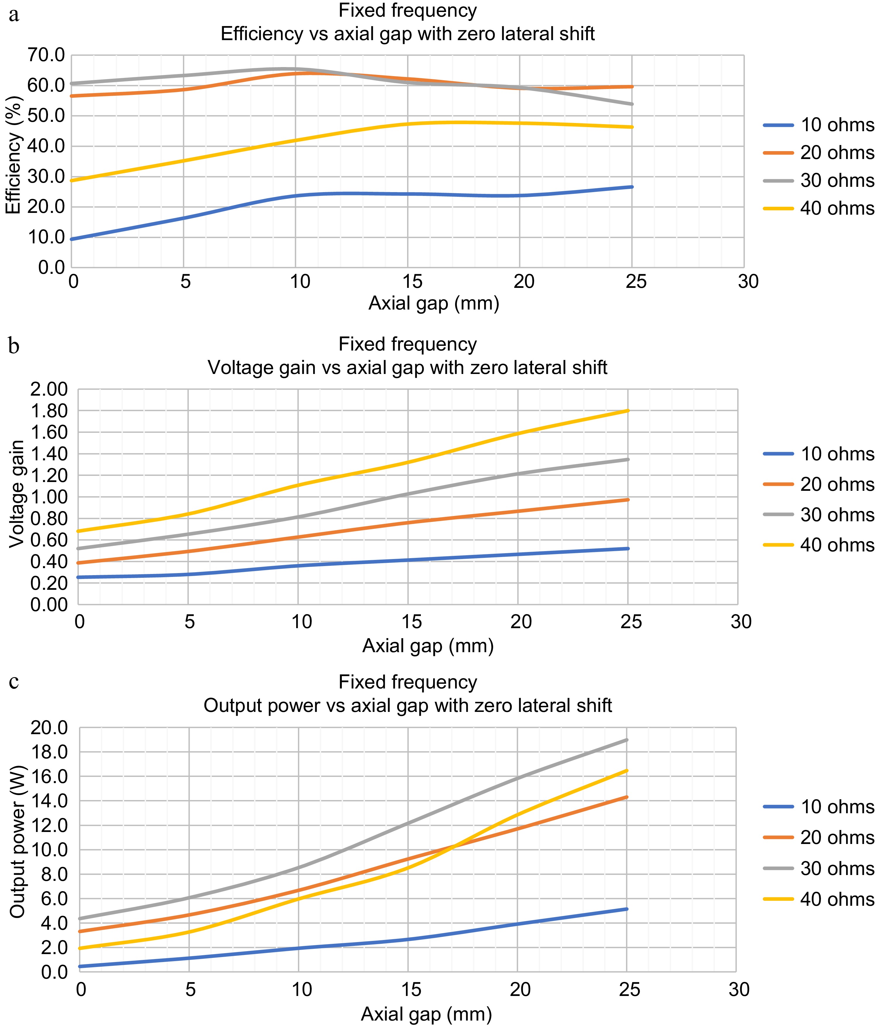
Figure 4.
Dynamic Response of TETS without any control for axial gap variations and load variations. (a) Efficiency vs axial gap for zero lateral shift. (b) Voltage gain vs axial gap for zero lateral shift. (c) Output power vs axial gap for zero lateral shift.
Frequency response
-
For simplicity in analysis and to understand the relationship of various electrical parameters with frequency, a lumped model of the two-coil transcutaneous energy transfer system is developed as shown in Fig. 1. The lumped model consists of a first loop made of the equivalent AC resistance, capacitance, and leakage inductance of the primary coil coupled to a secondary loop through mutual inductance. The secondary loop consists of AC resistance, capacitance, and leakage inductance of the secondary coil connected to a load resistance. By using Kirchhoff's laws, the expressions for the primary loop and secondary loop are deducted as shown in Eqns (1) & (2).
Applying Kirchhoff's laws to the primary loop
$ {U_1=Z_1I_1-j\omega MI_2} $ (1) Applying Kirchhoff's laws to the secondary loop
$ {0=-j\omega MI_1+Z_2I_2} $ (2) The expressions for the primary loop and secondary loop shall be combined to make the state space model of the TETS system as shown in Eqn (3).
$ {\begin{bmatrix}U_1\\0\end{bmatrix}=\begin{bmatrix}Z_1&-j\omega M\\-j\omega M&Z_2\end{bmatrix}\begin{bmatrix}I_1\\I_2\end{bmatrix}} $ (3) The state space model is solved to obtain the primary current, input impedance, secondary current, output impedance, mutual inductance, power delivered and efficiency as given in Eqns (4)−(10).
$ Primary\; Current,\ \ \ \ \; I_1=\dfrac{Z_2U_1}{Z_1Z_2+\omega^2M^2} $ (4) $ Secondary\; Current,\ \ \ \ \; I_2=\dfrac{U_1}{\dfrac{Z_1Z_2+\omega^2M^2}{j\omega M}} $ (5) where,
$ Mutual\; Inductance,\, \ \ \ \ M=k\sqrt{L_{l1}\times L_{l2}} $ (6) $ Primary\; Impedance,\; \ \ \ Z_1=R_{pri}+j\omega L_{l1}-\dfrac{1}{j\omega C_1} $ (7) $ Secondary\; Impedance,\; \ \ \ Z_2=R_{sec}+j\omega L_{l2}-\dfrac{1}{j\omega C_2}+R_{eq} $ (8) 'Req' Equivalent resistance of load seen from input of rectifier
$ \begin{split}Primary\; Resistance,\; \ \ \ R_{pri}=2\times R_{mosfet}+R_{skin}+R_{proximity}+R_{ESR}\end{split} $ (9) $ Secondary\; Resistance,\; \ \ R_{sec}=2\times R_{diode}+R_{skin}+R_{proximity}+R_{ESR} $ (10) where, Rmosfet and Rdiode are the resistance of the power electronic switches in the primary side and secondary side respectively; Rskin is the resistance of the coil due to the skin effect; Rproximity is the resistance changes due to proximity effect; RESR is the effective series resistance of the coil.
The equation for primary side power, secondary side power, is deducted as factors of primary current, input impedance, secondary current, output impedance, and mutual inductance as given in Eqns (11) & (12).
$ Primary\; Power,\; \ \ \ P_{pri}=U_1I_1=\dfrac{Z_1U_1^2}{Z_1Z_2+\omega^2M^2} $ (11) $ {Secondary\;Power,}\;\;\;\;P_{{sec}}=I_2^2R_{{load}}=\dfrac{\omega^2M^2U_1^2R_{{load}}}{(Z_1Z_2+\omega^2M^2)^2}\tag{12} $ (12) The ratio of secondary side voltage to the primary side voltage is known as voltage gain. Using the expressions for the primary side current and secondary side current, the voltage gain is deducted as given in Eqn (13).
$ G_v=\dfrac{j\omega MR_{eq}}{Z_1Z_2}\tag{13} $ (13) Using the expressions for secondary side power and the primary side power, the overall efficiency of the system is deducted as given in Eqn (14).
$ {{Overall}}\;{Efficiency,}\;\;\;\;Eff = \dfrac{P_{sec}}{P_{pri}}=\dfrac{\omega^2M^2U_1^2R_{load}}{(Z_1Z_2+\omega^2M^2)^2}\tag{14} $ (14) From the mathematical model, it can be noted that the voltage gain, power output, and efficiency are not only related to frequency alone but to many parameters such as load variations and mutual inductance. The variation of mutual inductance indirectly represents the variation in distance between the coils. Thus to obtain a dynamic response of the TETS, the frequency response needs to be studied to understand the variation of the optimal resonant frequency with respect to axial gap, and load variations. For the same, the TETS is operated by varying the frequency of operation of the resonant converter in the range of 100−200 kHz. Figure 5 shows the variation of efficiency, voltage gain and power output for varying axial gap and load.
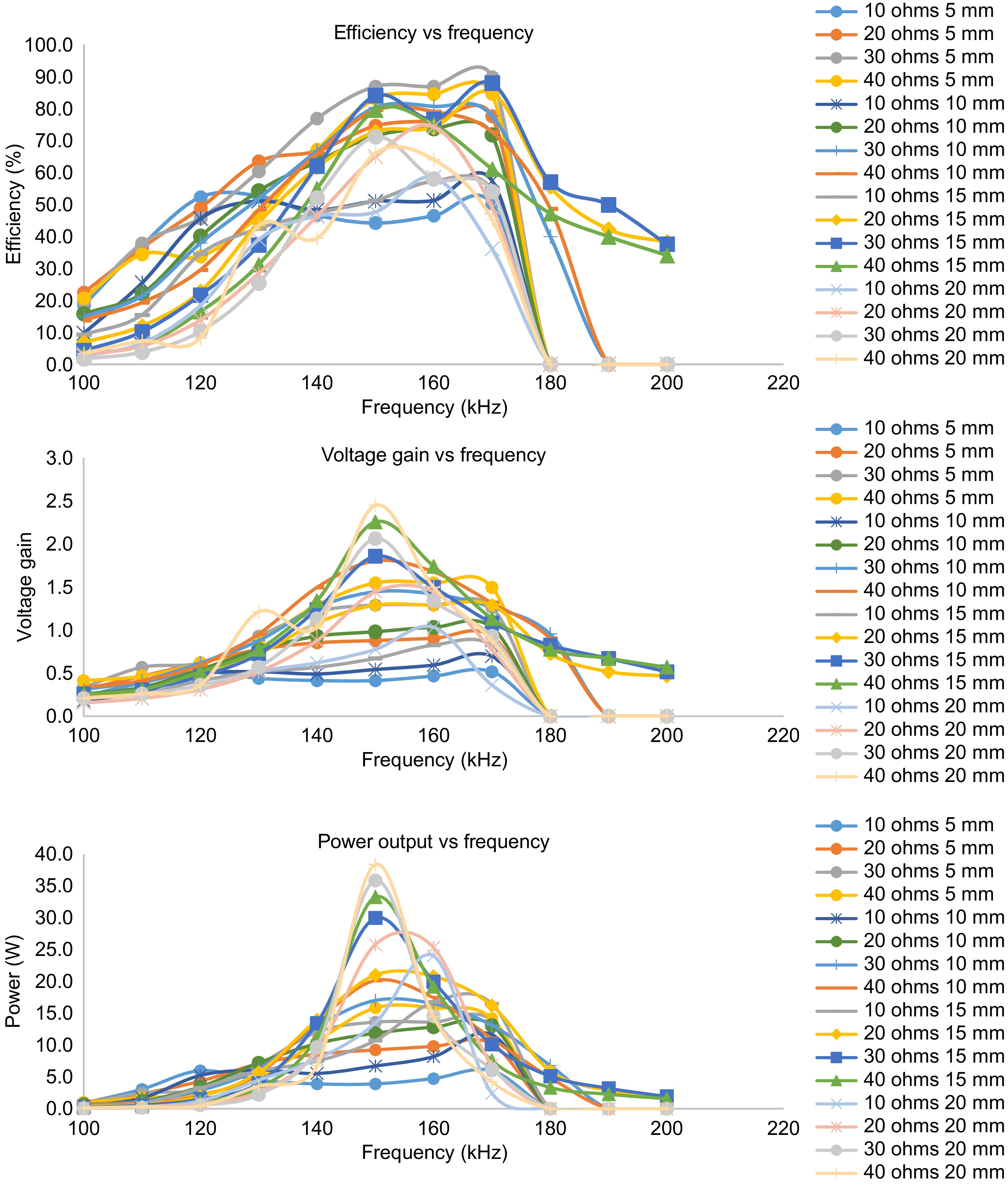
Figure 5.
Frequency response of TETS for axial gap variations and load variations.
It can be seen that, there exists an optimal frequency for every operating point in space around the coils, which is different than the design frequency. The efficiency, voltage gain, and power output show a bell curve pattern for the frequency sweep. For various load conditions and axial gap, the efficiency, voltage gain and power output becomes maximum between 150 to 170 kHz of operation. A maximum efficiency of 90% is obtained at 170 kHz with an axial gap of 5 mm. It can also be observed that at the optimal frequency, efficiency, voltage gain, and power output become maximum. With the increase in axial gap, the optimal operating frequency shifts from 170 kHz to the design frequency of 150 kHz. At high load resistance (less load current condition), the system could attain operating frequency till 200 kHz however no useful output power is obtained after 180 kHz of operation for low load resistance (heavy load current condition).
Optimal control for maximum power transfer with output voltage maximization
-
In a classical feedback control system, the output of the system is fedback and compared with a reference value to produce an error signal. The error signal is then given to a controller, which modifies the system output. Thus the error in the system is maintained within steady state error limits. To study the maximum power transfer condition, a similar approach is also applied to TETS. The voltage in the output is observed and the system frequency is adjusted to get the maximum output voltage at any operating point. The input voltage, input current, primary coil voltage, secondary coil voltage, output voltage, and output current are noted for various axial gap, and load conditions. A plot of the variation of efficiency, output power, and voltage gain with respect to the axial gap is shown in Fig. 6.
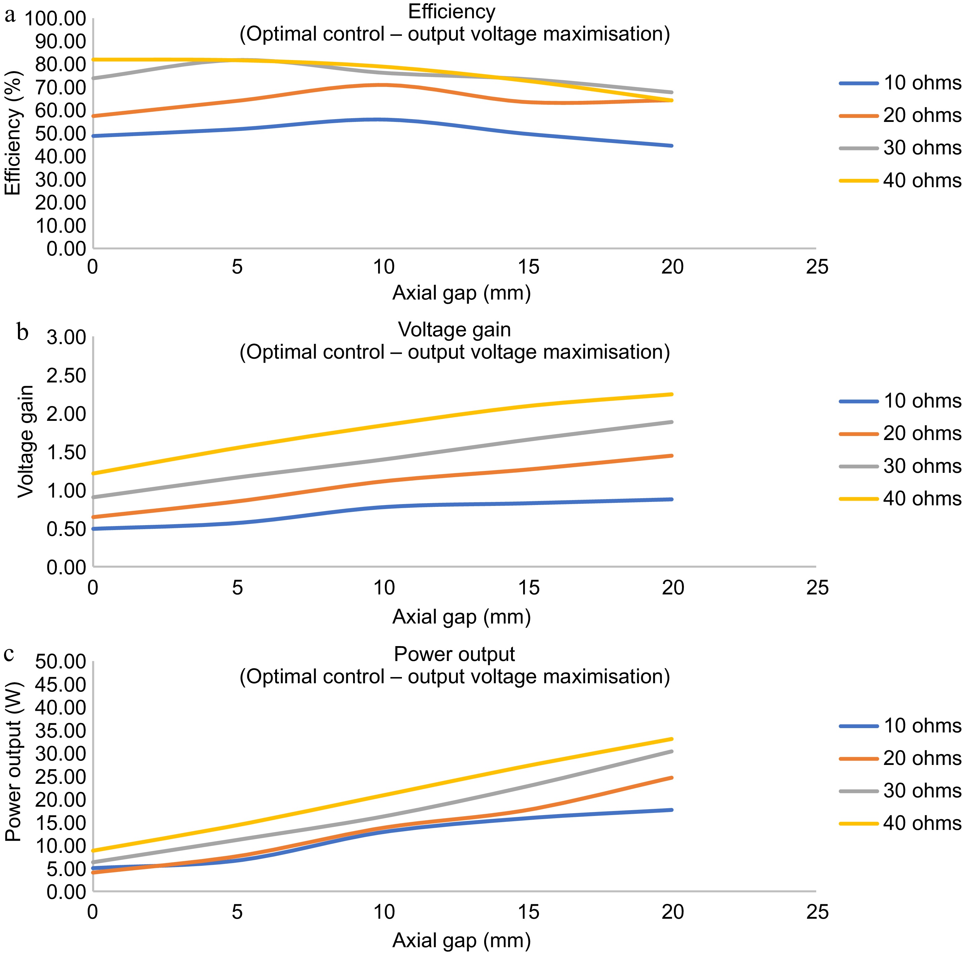
Figure 6.
Dynamic response of the TETS with for maximum power transfer with output voltage maximization. (a) Efficiency vs axial gap for zero lateral shift. (b) Voltage gain vs axial gap for zero lateral shift. (c) Output power vs axial gap for zero lateral shift.
The optimum frequency for the operation of the TETS at its maximum power transfer condition during any dynamic situation is plotted in Fig. 7a. It can be observed that the optimal frequency zones can be split into two zones of heavy load and light load conditions. During the light load conditions, the variation in the optimal frequency for different axial gaps does not vary much. However, there is a large variation in the optimal frequency during heavy load conditions. A better understanding of the optimal frequencies shall be done when the lateral shift is considered as zero. Figure 7b shows the optimal frequencies for the maximum power transfer with zero lateral shift. It can be seen that, for high load resistance conditions the optimal frequency varies with axial gap, whereas for less load resistance conditions the optimal frequency remains almost constant at 150 kHz.
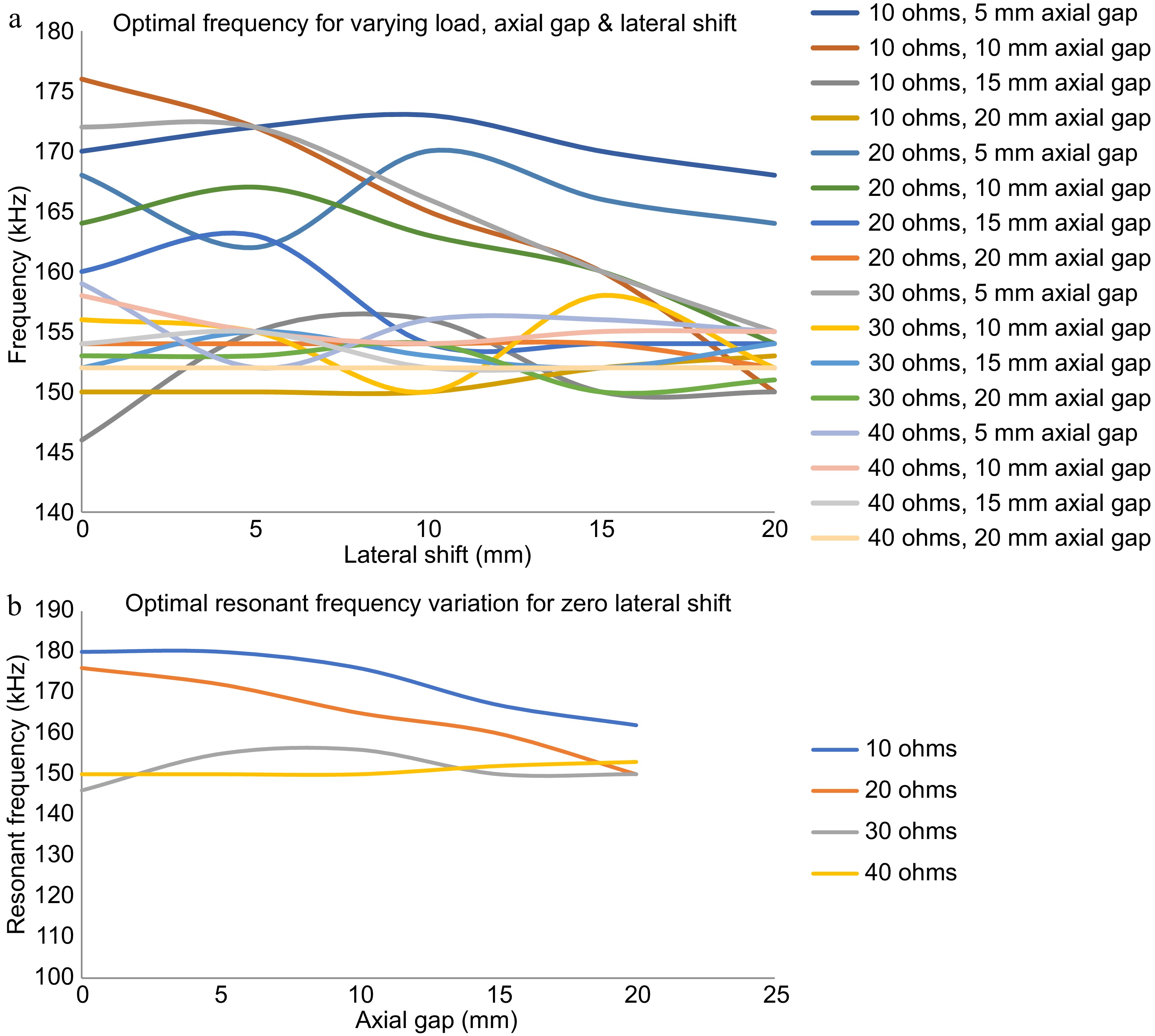
Figure 7.
Optimum frequency for the operation of the TETS at its maximum power transfer condition. (a) Optimum frequency for varying load, axial gap, and lateral shift. (b) Optimum frequency for varying load, axial gap with zero lateral shift.
Thus with continuous optimal control, the operation of the TETS can be maintained in its optimal conditions and maximum power transfer can be ensured. However, the dynamic response is highly sensitive to load and gap variations. Manual adjustment of frequency will be highly complicated. From Fig. 7b it can be inferred that by determining the position of the implanted coil, the optimal resonant frequency can be selected to operate TETS under maximum power transfer conditions. Hence an automated control corresponding to the axial gap by sensing the physical location of the secondary coil is presented below.
Automatic optimal control with magnetic position feedback
-
TETS would be placed in patients with various skin thicknesses. The thickness of the skin also increases with respect to time due to accumulation of adipose tissue. TETS tuned with fixed design operating frequency may not operate optimally when the skin thickness varies. Surgeons may have to carry out in situ adjustment to optimize the power delivery after implantation. This activity diverts his attention to focus on less important activities rather than focusing on LVAD and TAH operational conditions. Hence, to address the issue of varying skin thickness and thereby varying coil to coil separation, a magnetic position feedback mechanism as shown in Fig. 8 is presented.
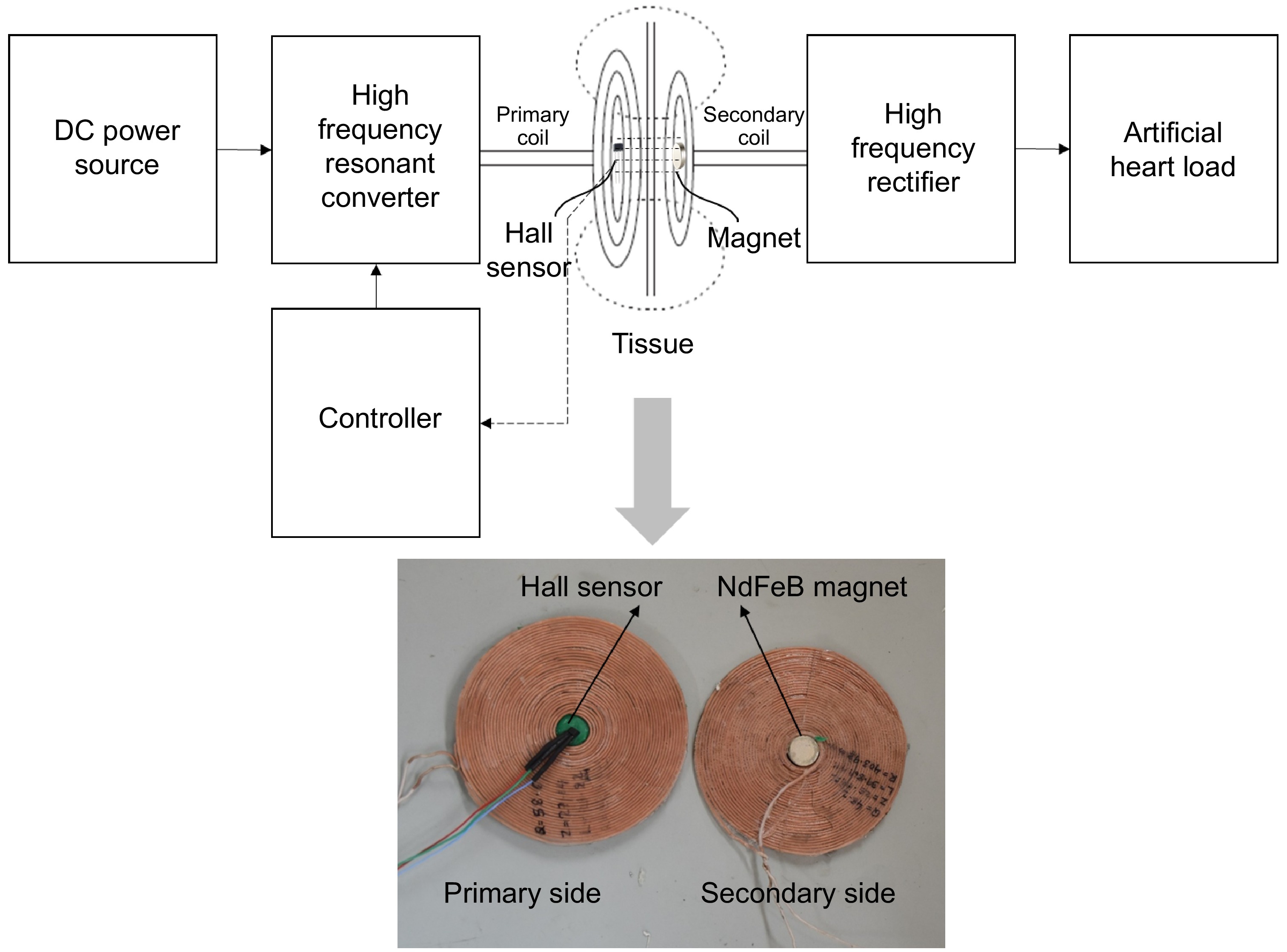
Figure 8.
Magnetic position feedback scheme.
A strong magnet, preferably made of Neobdium Iron Boron (NdFeB), is kept in the center of the spiral wound coil. The spiral wound coil has a free space in its center at which a Hall effect sensor is attached for detecting magnetic fields in its vicinity. The Hall effect sensor produces a voltage output when a magnetic field is sensed as shown in Fig. 9a. The output voltage produced by the Hall sensor is fed to the controller. The magnitude of the hall effect sensor output is proportional to the intensity of the magnetic field it senses. When the primary side coil and the implant get locked, the Hall effect sensor kept at the center of the transmitting coil comes under the influence of the magnetic field produced by the strong NdFeB magnet kept at the center of the implanted receiving coil. A voltage proportional to the magnetic field experienced at the center of the transmitting coil is produced in the Hall effect sensor. Apparently, this voltage generated is correlated to the distance between the two coils.
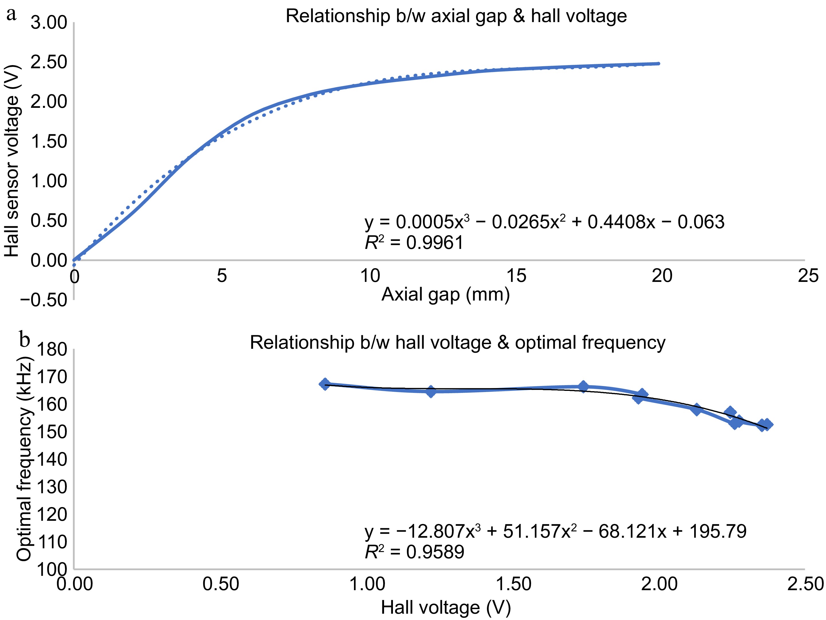
Figure 9.
Variation of hall sensor voltage with distance from implanted coil. (a) Hall sensor output vs axial gap. (b) Optimal frequency vs hall sensor voltage.
The hall effect voltage is given to the controller which then produces a suitable frequency to operate the resonant full bridge converter on the primary side using a calibration curve as shown in Fig. 9b. The controller is calibrated to produce a frequency signal corresponding to the hall voltage obtained such that, maximum power is transferred at the respective separation gap between the coils. In this way, for any coil-to-coil separation, a particular frequency signal is produced by the controller to trigger the full bridge resonant converter in the primary side for transferring maximum power to the secondary side. Thus, the automatic control of the transcutaneous energy transfer system is achieved for any coil-to-coil separation gap due to tissue thickness change, coil repositioning, person-to-person variation etc.
-
A large variation in system parameters of TETS is observed with variation in load and separation gap. For any point in space and load condition, there exists an optimal resonant frequency as shown in Fig. 7. Also, the optimal resonant frequency is different from the design frequency. Finding out the optimal resonant frequency is a challenging task in a dynamic environment such as LVAD, TAH, etc. An automatic optimal control strategy using magnetic position feedback control is presented here. To test the performance of the control strategy, the TETS is operated in a dynamic condition with variation in the axial gap and lateral shift in the range of 0 to 20 mm as well as the load resistance varying from 10 to 40 ohms. A low resistance represents a heavy load condition for operating TAH and LVAD whereas a high resistance represents light load conditions for charging an implantable battery. The results of various tests performed and their analysis are given below.
In Vitro test with dynamic conditions
-
In magnetic position feedback, the position of the implanted coil is indirectly determined using the hall sensor kept on the primary coil. The variation of the hall sensor voltage with respect to lateral shift and axial gap is provided in Fig. 9. For each axial gap, the TETS is operated to obtain the maximum power transfer condition, and the optimal frequency is taken. A relationship is established between the optimal frequency and the hall sensor voltage corresponding to each axial gap as shown in Fig. 9b. A third-degree polynomial with an R2 value of 0.9589 is fitted into the relationship. The TETS is operated in automatic mode with magnetic position feedback control to obtain the dynamic response for the axial gap, lateral shift, and load variations. The variation of efficiency, voltage gain, and power output for these variations with automatic control is provided in Fig. 10.
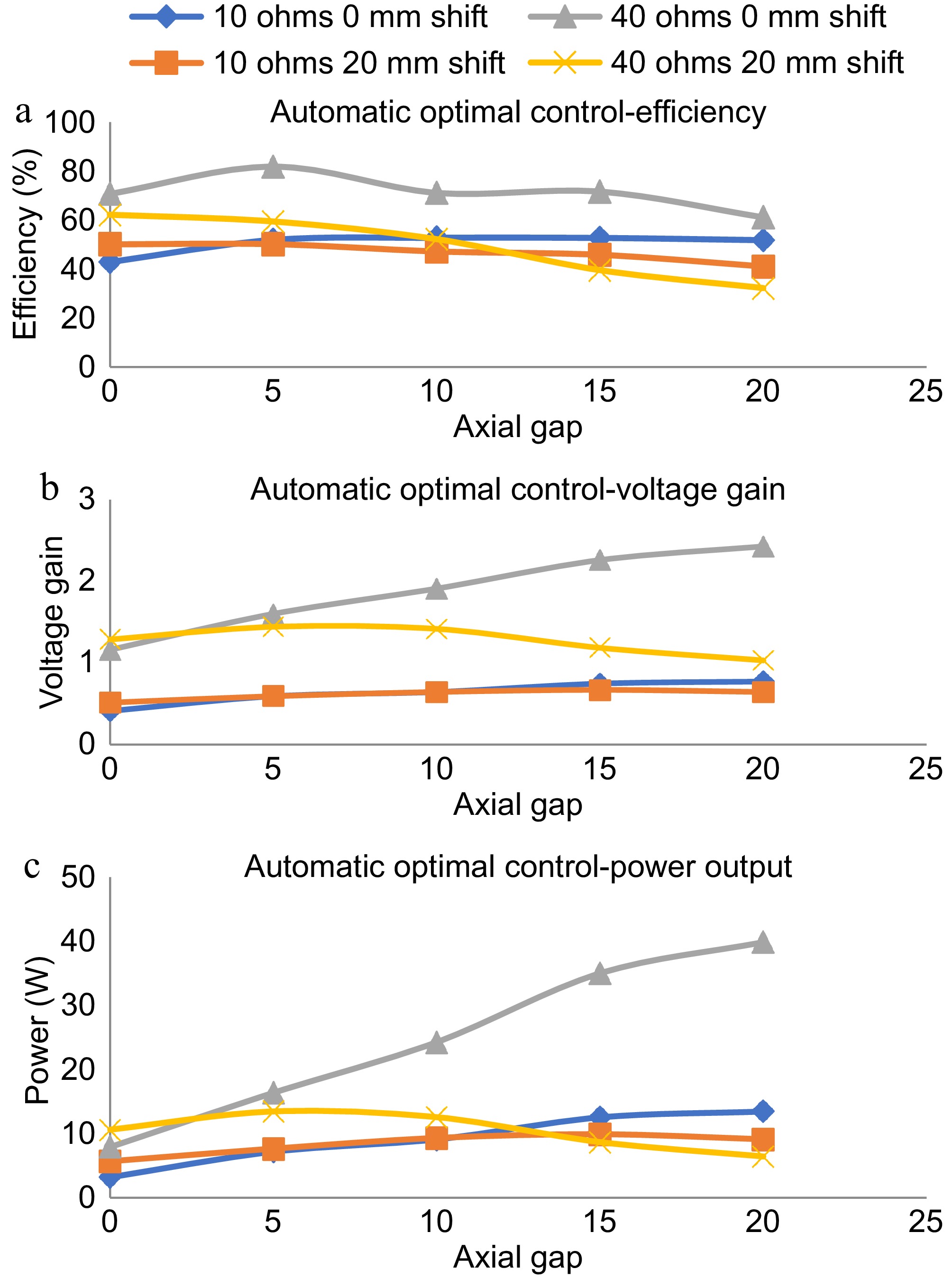
Figure 10.
Dynamic response with magnetic position feedback based automatic optimal control. (a) Efficiency plot in automatic optimal control. (b) Voltage gain plot in automatic optimal control, power output plot in automatic optimal control.
As shown in Fig. 10a, the efficiency of the TETS remains within a small variation for the variations in axial gap and lateral shift in the range of 0 to 20 mm. The variation in load resistance makes the efficiency to vary between 50% to 80% in the entire operational range. The maximum efficiency is obtained for the 40 ohms load condition with zero lateral shift at a 5 mm gap. As shown in Fig. 10b, the voltage gain shows minimal variation for conditions except 40 ohms with zero lateral shift. For 40 ohms with zero lateral shift, a linear variation in the voltage gain is observed increase in the axial gap. With less resistance conditions (10 ohms), not much variation is observed for the changes in the lateral position in the range of 10 to 20 mm. For high resistance conditions (40 ohms), the voltage gain showed a 20% variation (1.2 to 1.0) with an increase in axial gap. As shown in Fig. 10c, an overall variation of 5 W to 40 W is obtained with the entire operating range. For low resistance conditions, the TETS could transfer a power up to 15 W. The maximum power transfer occurred in the axial gap of 15 to 20 mm. No major difference in the power delivery characteristics is noticed for the variation in lateral shift at 10 ohms load condition.
In Vitro test with animal tissue
-
To analyze the performance of TETS in clinical conditions, In Vitro tests were performed with bovine tissue obtained from the slaughter house. A 100 mm × 100 mm square piece of 10 mm thick bovine tissue was placed between TETS coils as shown in Fig. 11. The system is operated with a 15 V input and varying load conditions. The efficiency, power output, and voltage gain of the system was analyzed without any control as well as with magnetic position feedback, and perturbation control methods. The results of the experiment are provided in Fig. 12. With the proposed TETS system, power up to 15 W can be delivered at a 10 mm gap which is suitable for LVAD and TAH applications. It can be found that optimal control is required for high-current applications. For lighter loads no major changes were observed.
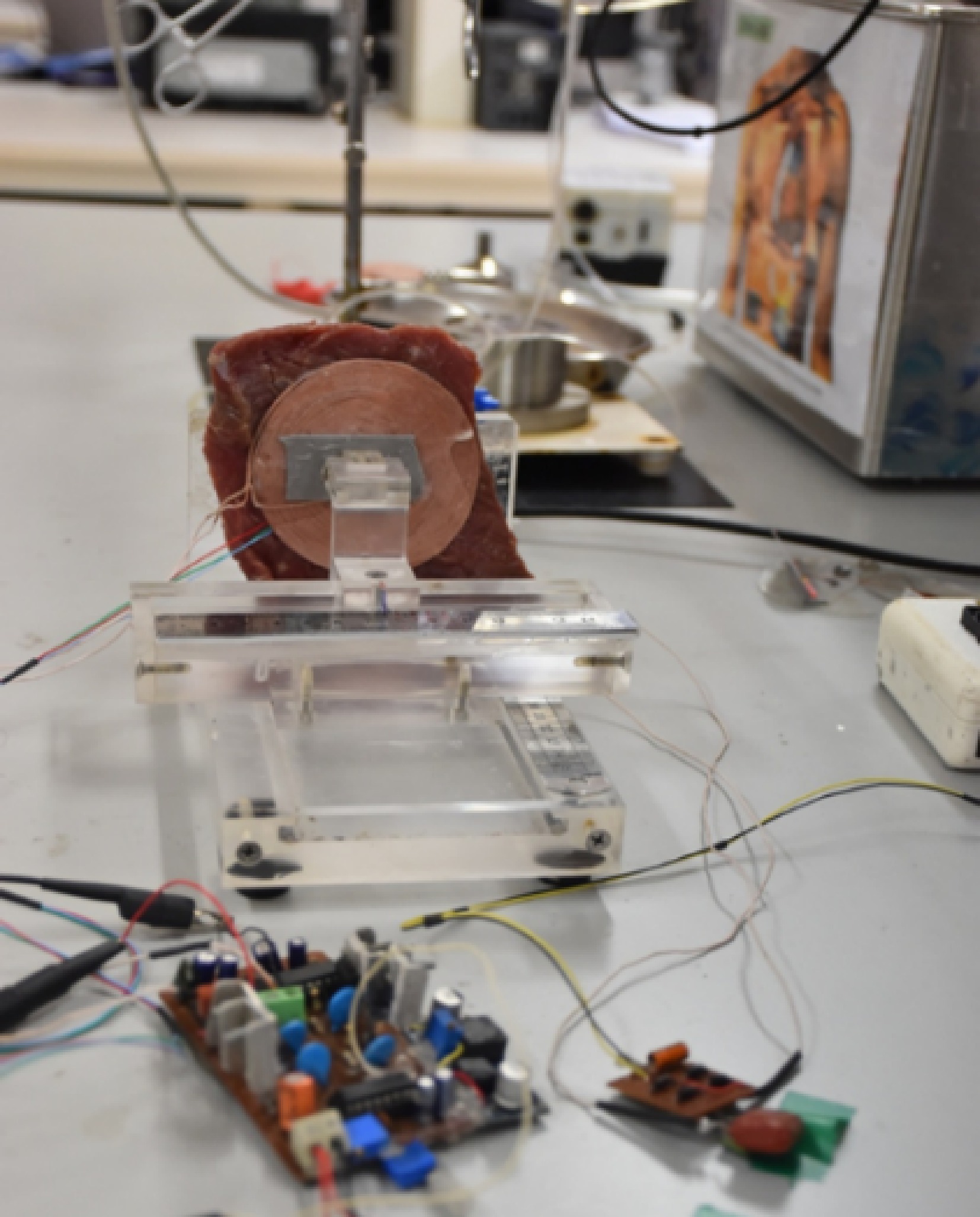
Figure 11.
In Vitro tests with animal tissue.
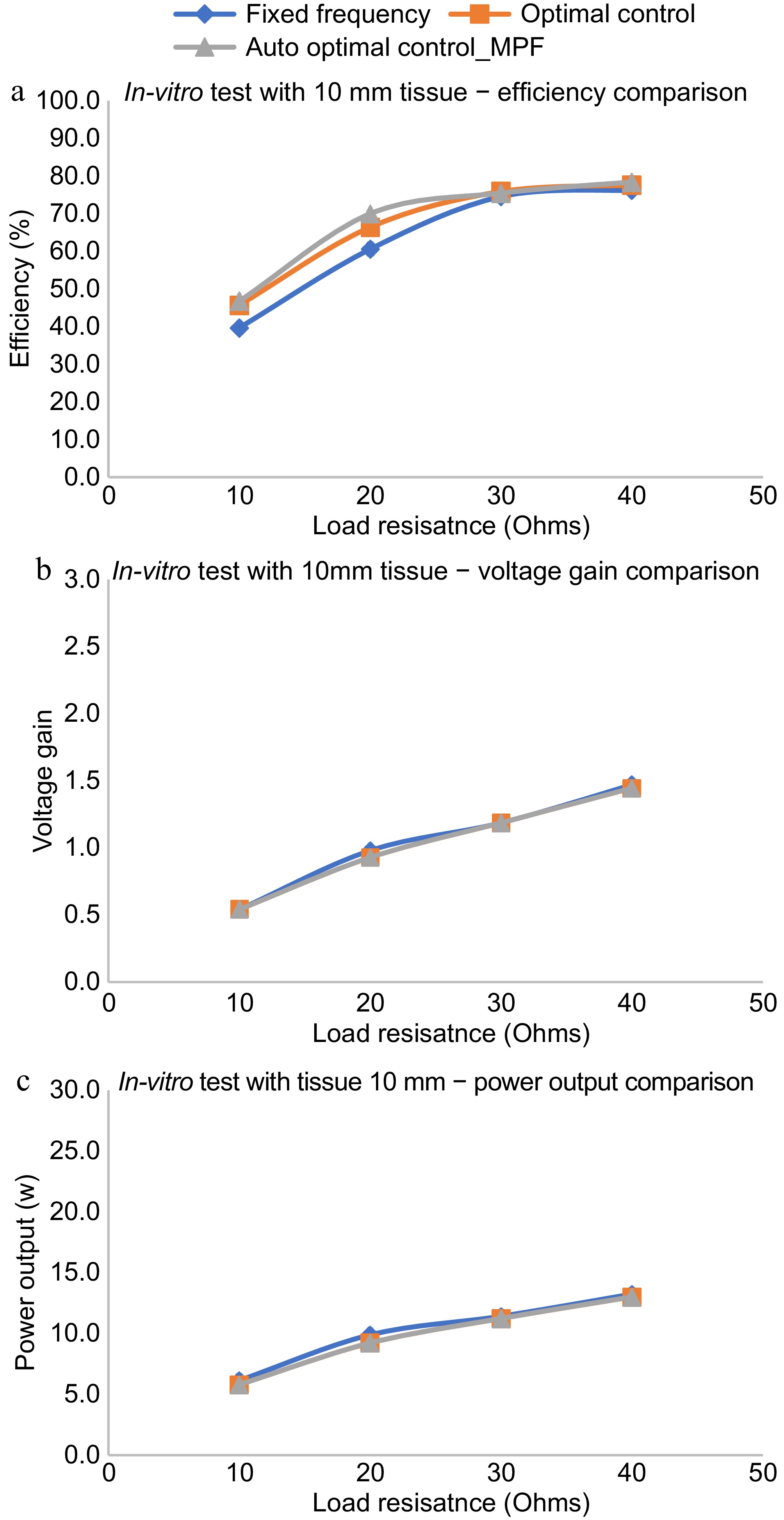
Figure 12.
In Vitro performance evaluation with animal tissue. (a) Efficiency comparison with various control schemes. (b) Voltage gain comparison with various control schemes. (c) Power output comparison with various control schemes.
As shown in Fig. 12a, the efficiency of the auto-optimal control using magnetic position feedback is almost the same as that of the optimal control using manual methods with tissue of thickness 10 mm. The variation is seen only for one observation of the efficiency plot given in Fig. 12a at a load resistance of 20 ohms which may be due to measurement error. The error may be eliminated by conducting a detailed In Vitro performance evaluation and averaging the results of multiple tests. Also, it can be found that the efficiency for the said tissue thickness is better than the fixed frequency regime. The voltage gain as well as the power output varies in the same manner for all the control regimes for various load conditions as shown in Fig. 12b & c. Power up to 15 W can be delivered with a tissue thickness of 10 mm.
Implantation study
-
The TETS system was placed subcutaneously on a sheep carcass to understand the thermal rise of the system during its operation as shown in Fig. 13. Animal ethics approval (IAEC\TR\01\Y-2023) was obtained from the Institutional Animal Ethics Committee (IAEC) of Sree Chitra Tirunal Institute for Medical Sciences and Technology (SCTIMST), (Statutory Body and An Institute of National Importance, Department of Science and Technology, Government of India). A sheep model with sufficient skin thickness was selected and was found suitable for the purpose. All experimental procedures were conducted according to the guidelines provided by the Animal Care Committee. The sheep carcass was prepared for the experiment and a suitable site located in the abdomen. A 70 mm long incision was carried out to insert the receiving coil. The thickness of the skin and tissue was measured using a Vernier caliper. The receiving coil was kept within the abdomen and the output cable connected to a rheostat kept outside. The skin was sutured with the exit cable running out from the body. A thermos couple was kept over the skin at the implanted site. The transmitting coil was kept over the implanted site. The system was automatically set to operate for the frequency corresponding to the depth of implantation as discussed in the previous sessions. A resistive load of 20 ohms was set on the rheostat and the transmitting circuitry turned on. The system was controlled as discussed in the previous session and an optimal frequency provided. The thermocouple was connected to a Fluke multimeter to measure the temperature rise at the site of implantation, between the coils. The voltage and the current of the TETS system were measured using a voltmeter and clamp on ammeter respectively.
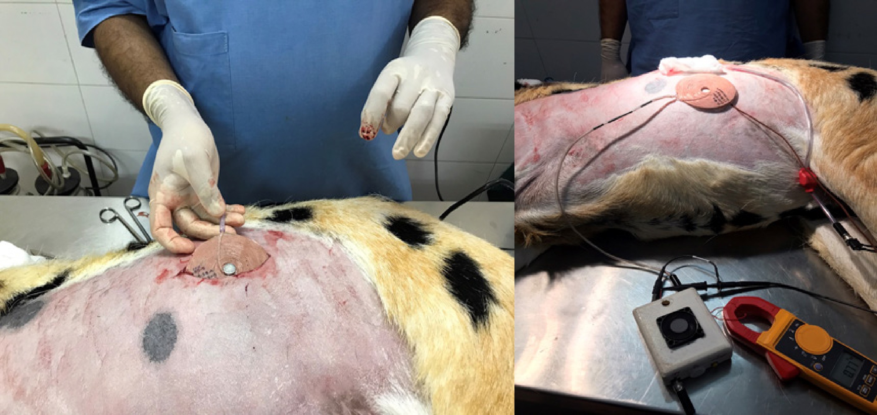
Figure 13.
TETS implantation study.
The rise in temperature from the experiment is shown in Fig. 14. The skin temperature rose to a maximum value of 40 °C in the first 20 min, and remained stable thereafter.
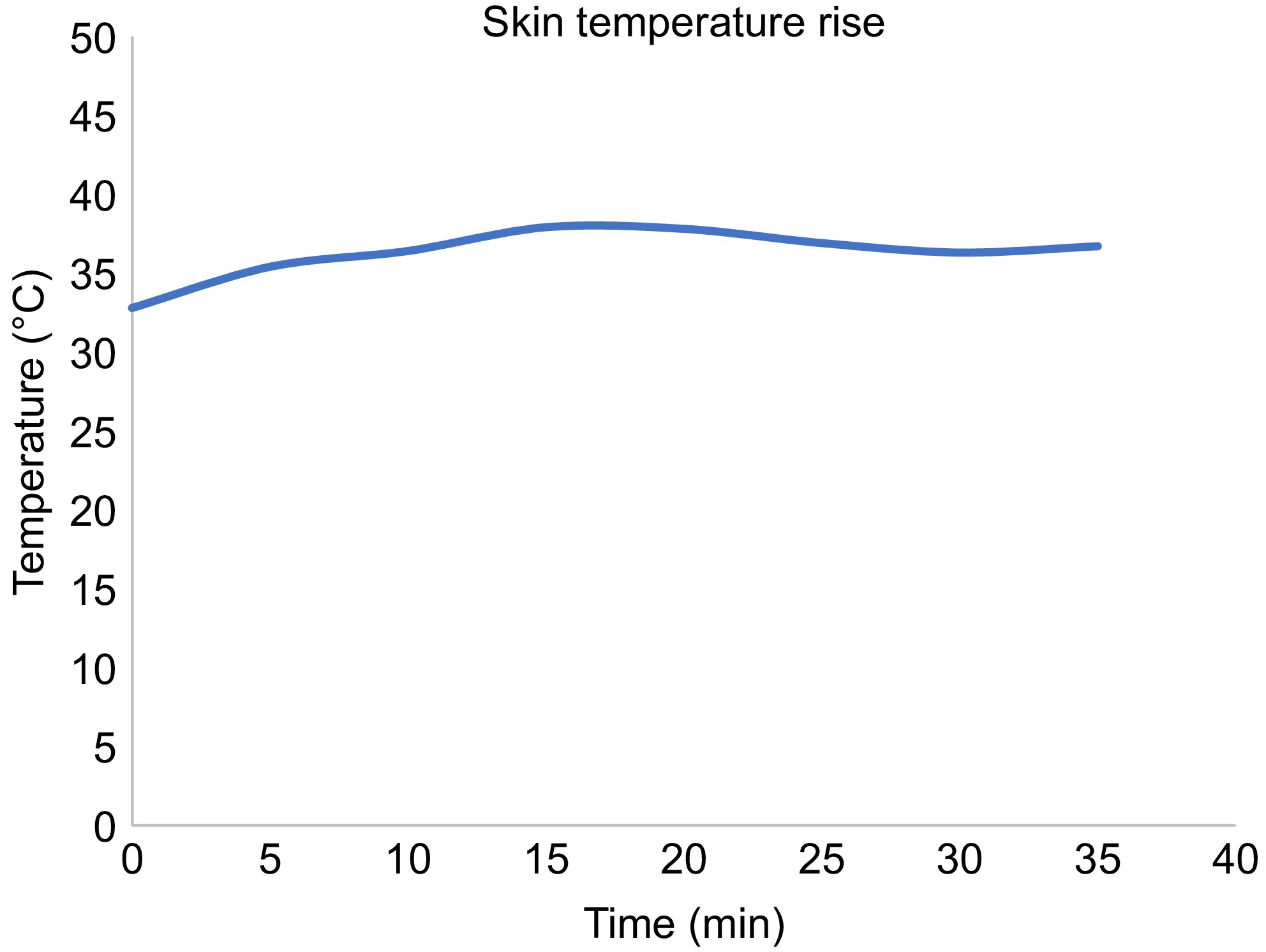
Figure 14.
Thermal rise at the implanted site.
-
A high percentage of the world population suffers from end-stage heart failure, which may lead to the need for heart transplantation. A left ventricular assist device (LVAD) may be required for deteriorating patients whilst on the waiting list for a transplant or long-term support (destination therapy) in those patients who are not eligible for a transplant. Current available devices are powered by a driveline, which is tunneled through the skin and connected to an external power supply leading to the potential for complications such as infection and device malfunction requiring frequent hospital admissions. A transcutaneous energy transfer system (TETS) is a promising approach to power cardiac assist devices wirelessly through the skin and improve the current limitations.
The practical use of wireless energy transfers to recharge or power an implantable medical device is restricted by the varying thickness of the skin, and dynamic conditions like orientation changes, lateral shift, respiration, posture variations, and physical movement. Unlike the case of a consumer electronic device, a total artificial heart or a left ventricular assist device are lifesaving medical devices that cannot be interrupted for even a second. The interruptions in power adversely affect the operation of the device and may end up in patient mortality. Unlike conventional wireless charging, where the batteries are recharged for a particular duration, the artificial heart is continuously powered by the TETS system. The implanted batteries will be in a floating charge condition which are operated only during emergency backups.
The conventional TETS system has a primary transmitting coil and a secondary receiving coil. The primary coil is kept over the skin and the secondary receiving coil is implanted and sutured to the muscles. Once implanted, it will be difficult to identify the secondary coil and place the primary coil over it. The varying thickness is a concern for optimal operation of the system. The patient skin or tissue thickness may vary due to age, skin location, person-to-person. The thickness of a pediatric patient will be different from an adult or aged person. The TETS is supposed to operate in its optimal point for all these situations. So, any changes in the operating environment of TETS will seriously affect the implanted device operation. To address this unmet clinical need, an automatic optimal control is proposed
In this paper, an automatic optimal control of transcutaneous energy transfer system for powering active implantable medical devices such as artificial hearts is discussed. The paper proposes methods for automatically achieving the optimal condition of maximum power delivery across the skin using a combination of two strategies. In the first strategy, the optimal performance of the TETS system is studied using a manual control method, and the frequencies required to be set for operating the TETS in any dynamic condition are deducted. In the second strategy, a magnetic position feedback is provided to indirectly measure the distance between the coils, and a correlation is developed between the distance and the deducted optimum frequency points. In the magnetic position feedback, a strong NdFEB magnet is placed in the center of the implanted coil and a hall effect sensor is placed in the center of the primary coil. The hall sensor produces a voltage proportional to the magnetic field it experiences from the secondary coil magnet. A microcontroller in the primary side circuit obtains this voltage and provides optimal operating frequency after fitting to a calibration curve.
To understand the behavior of the TETS under these dynamic situations, frequency response, efficiency, voltage gain, and power output of the system is studied. The study includes varying the environment parameters suitable for most of the active implanted medical devices in the power range of a few watts to tens of watts as required by the artificial heart and an axial gap and lateral shift in the range of 0 to 20 mm. It was found that the TETS could deliver up to 30 W at an axial distance and a lateral shift of 20 mm. Extensive In Vitro, tissue, and animal studies have been performed to evaluate the dynamic performance of this system under variation in load axial gap and lateral shift with fixed frequency, manual, and automatic control. The performance of this system was tested with an animal tissue thickness of 10 mm resulting in more than 70% efficiency. The system was then tested with an animal carcass model to understand the skin temperature variation.
The efficiency of the TETS remains within a small variation for the variations in axial gap and lateral shift in the range of 0 to 20 mm. The variation in load resistance makes the efficiency vary between 50% to 80% in the entire operational range. The maximum efficiency is obtained for the 40 ohms load condition with zero lateral shift at a 5 mm gap. The voltage gain shows minimal variation for conditions except 40 ohms with zero lateral shift. With less resistance conditions (10 ohms), not much variation is observed for the changes in the lateral position in the range of 10 to 20 mm. For high resistance conditions (40 ohms), the voltage gain showed a 20% variation (1.2 to 1.0) with an increase in axial gap. An overall all variation of 5 to 40 W is obtained with the entire operating range. For low resistance conditions, the TETS could transfer a power up to 15 W. The maximum power transfer occurred in the axial gap of 15 to 20 mm. No major difference in the power delivery characteristics is noticed for the variation in lateral shift at 10 ohms load condition. With In Vitro testing using bovine tissue, the efficiency of the auto optimal control using magnetic position feedback is almost the same as that of the optimal control using manual method with tissue of thickness 10 mm. Also, it can be found that the efficiency for the said tissue thickness is better than the fixed frequency regime. The voltage gain as well as the power output varies in the same manner for all the control regimes for various load conditions. A power up to 15 W can be delivered with a tissue thickness of 10 mm. The TETS system is implanted on the sheep carcass to understand the thermal rise of the system during its operation. The sheep carcass is prepared for implantation and a suitable site is located in the abdomen. The system is automatically set to operate for the frequency corresponding to the depth of implantation with a load resistance of 20 ohms. The skin temperature rose to a maximum value of 40 °C in first 20 min, and remained stable thereafter.
-
Heart transplantation is required for a large percentage of the world population suffering from end-stage heart failure. Research on advanced artificial heart is booming all across the world as the availability of donor hearts is not meeting the demand. Artificial hearts in the form of left ventricular assist device (LVAD) may be required for deteriorating patients whilst on the waiting list for a transplant or for long-term support (destination therapy) in those patients who are not eligible for a transplant. Many new generations of such LVADs have been investigated for their biocompatibility, reliability, and better hemodynamic performance which can support destination therapy where the patients live with an artificial heart The best-in-class LVAD needs a percutaneous cable entry for powering it from outside the human body. Failure due to infections in the cable entry sites is a major concern that need to be addressed. Making use of wireless energy transfer across skin will reduce the failure due to percutaneous connection and will be an added advantage in the journey to make perfect, totally artificial heart and ventricular assist devices suitable for destination therapy.
Research is in progress to adapt the performance of the artificial heart to physiological demands. In such situations, the patients will have better mobility and hence TETS are supposed to operate in dynamic environments. In this paper, an automatic optimal control of transcutaneous energy transfer system for powering artificial hearts in dynamic environments is discussed. The paper proposes methods for automatically achieving the optimal condition of maximum power delivery across the skin. In Vitro, tissue, and animal carcass experiments show promising results in the approach. It is envisaged that the automatic optimal controlled TETS will be a beneficiary feature for the artificial hearts of the future. Future work in this direction involves the increase in efficiency near 100% with better thermal dissipation. Future study shall be focused on analyzing the effect of radiating electromagnetic waves from the TETS on wearable diagnostic devices. The compatibility of the proposed TETS with magnetic resonance imaging also need to be investigated.
-
All experimental procedures were conducted according to the guidelines provided by the Animal Care Committee. Animal ethics approval (IAEC\TR\01\Y-2023) was obtained from the Institutional Animal Ethics Committee (IAEC) of Sree Chitra Tirunal Institute for Medical Sciences and Technology (SCTIMST), (Statutory Body and An Institute of National Importance, Department of Science and Technology, Government of India) nominated by the Committee for the Control of Supervision of Experiments on Animals (CCSEA), Department of Animal Husbandry and Dairy, Ministry of Fisheries, Government of India.
-
The authors confirm contribution to the paper as follows: study conception and design, data collection, analysis: Nair SS; animal evaluation: Shenoy SJ; interpretation of results: Nair SS, Harikrishnan S; draft manuscript preparation: Nair SS, Harikrishnan S. All authors reviewed the results and approved the final version of the manuscript.
-
The data that support the findings of this study are available from the corresponding author upon reasonable request.
-
The authors would like to thank the Indian National Academy of Engineering for funding the project through INAE-SERB, DST Abdul Kalam Technology Innovation National Fellowship, 2023. The authors would also like to thank all the staff of the Division of In vivo Models and Testing as well as the Division of Extracorporeal Devices of the Department of Medical Devices Engineering, Biomedical Technology wing, SCTIMST for their support in developing and testing the method described in the paper.
-
The authors declare that they have no conflict of interest.
- Copyright: © 2025 by the author(s). Published by Maximum Academic Press, Fayetteville, GA. This article is an open access article distributed under Creative Commons Attribution License (CC BY 4.0), visit https://creativecommons.org/licenses/by/4.0/.
-
About this article
Cite this article
Nair SS, Shenoy SJ, Harikrishnan S. 2025. Automatic optimal control of transcutaneous wireless energy transfer system with magnetic position feedback. Wireless Power Transfer 12: e008 doi: 10.48130/wpt-0025-0001 

Automatic optimal control of transcutaneous wireless energy transfer system with magnetic position feedback
- Received: 10 September 2024
- Revised: 10 December 2024
- Accepted: 31 December 2024
- Published online: 02 April 2025
Abstract: A high percentage of the world population suffers from end-stage heart failure, which may lead to the need for heart transplantation. A left ventricular assist device (LVAD) may be required for deteriorating patients whilst on the waiting list for a transplant or for long-term support (destination therapy) in those patients who are not eligible for a transplant. Currently available devices are powered by a driveline, which is tunneled through the skin and connected to an external power supply leading to the potential for complications such as infection and device malfunction often requiring frequent hospital admissions. A transcutaneous energy transfer system (TETS) is a promising approach to power cardiac assist devices wirelessly through the skin and improve the current limitations. Unlike conventional wireless recharging technology, TETS must operate in a dynamic environment including body posture changes, body movements, and varying skin thickness, which may affect power delivery and efficiency. In this paper, an automatic optimal control strategy is described for a TETS device consisting of magnetic position feedback. Extensive In Vitro, tissue, and animal studies have been performed to evaluate the dynamic performance of this system under variation in load axial gap and lateral shift with fixed frequency, manual, and automatic control.