


-
With the rapid advancement of unmanned aerial vehicle (UAV) technology and continuous innovation in wireless communication networks, unmanned aerial vehicles (UAVs) have emerged as a pioneering force in promoting the deep integration of communication and perception technologies[1−4]. As a cutting-edge trend in network evolution, communication-perception integration (CPI) corely relies on physical infrastructure and resource sharing to significantly enhance system-wide efficiency and adaptability[5−7]. UAVs, with their unique aerial perspective, excellent maneuverability, and rapid response capabilities, enable wide coverage of communication networks and precise acquisition of perception data, thereby opening new avenues for CPI implementation. In this context, analyzing the core role and precise positioning of UAVs in CPI systems becomes particularly urgent. Designing efficient resource allocation and scheduling strategies based on such analysis not only maximizes UAV-specific advantages but also directly influences the intelligent and flexible development of future network systems. This endeavor is crucial for harnessing the full potential of UAVs in next-generation integrated networks.
The UAV resource allocation problem mainly focuses on trajectory optimization, channel allocation, and power control[8−12]. The trajectory optimization problem of multiple three-dimensional UAVs as aerial base stations (BS) was studied[8]. Wireless coverage for Internet of Things (IoT) devices is considered by optimizing the trajectory and power of drones to minimize communication time for all IoT devices. Furthermore, a solution based on Hierarchical Reinforcement Learning (HRL) has been proposed. In reliability-oriented downlink wireless network assisted by drones, a deep embedding deterministic policy gradient (DDPG) algorithm was proposed, and the trajectory and transmission power allocation of unmanned aerial vehicles were jointly determined through alternately optimizing iterative schemes[9].
The application of unmanned aerial vehicles in auxiliary hybrid non-orthogonal multiple access (NOMA) systems was studied[10]. To improve UAV spectrum efficiency and communication connectivity, a joint optimization model for UAV positioning and user grouping that maximizes system speed was established. Finally, the paper swarm optimization algorithm and neural network method were used to iteratively solve the problem. Channel allocation and power control for uplink NOMA-assisted multi-UAV networks were researched[11]. A mixed integer nonlinear programming model was established, and a feasible algorithm proposed to obtain the power and channel allocation scheme for the drone. A drone relay network based on NOMA was studied[12]. A joint optimization model for NOMA user grouping, drone location, and drone transmission power were established. Similarly, an iterative algorithm was used to obtain an approximate optimal solution.
The resource allocation problem of sensory integrated systems was studied[13−15]. In the scenario of unmanned aerial vehicle multi-cell collaborative integrated sensing and communication (ISAC), a collaborative control strategy for base station power and unmanned aerial vehicles was designed, considering the maximization of QoS (Quality of Service), and communication efficiency[13]. To ensure the safety of ISAC-UAV systems, a joint optimization algorithm for UAV trajectory and launch power was proposed[14], maximizing the secure communication rate under the constraints of UAV maneuverability, power, and perception. In multi UAV assisted dual function base station (BS) scenarios, a Stackelberg game model was proposed to consider the physical layer security of ISAC signals[15].
In recent years, the energy consumption issue of UAVs has attracted increasing attention[16−25]. The application of energy harvesting (EH) technology in unmanned aerial vehicle communication scenarios was studied[16]. A rate-limited solution for UAV networks was proposed through UAV-assisted communication and EH channel modeling. An EH scheme based on the UAV-RIS system was proposed, enabling simultaneous signal transmission, and energy harvesting on the RIS metasurface[17]. A robust near-end policy optimization algorithm has been developed with QoS as a constraint in dynamic wireless environments. A graph theory-based UAV energy harvesting assisted communication resource allocation algorithm was proposed[18]. A EH optimization model based on imperfect channel state information (CSI) was established and solved to maximize network throughput.
An EH scenario based on meta reinforcement learning (RL) was studied[19]. A joint optimization scheme for UAV trajectory and EH strategy was designed, taking QoS as the constraint condition, considering unmanned aerial vehicles with both energy collection and data transmission capabilities. An unmanned aerial vehicle RIS assisted maritime communication system in the presence of malicious interference was designed[20]. A problem of maximizing energy efficiency (EE) in an adaptive energy harvesting system was proposed by adjusting the position and surface elements of the RIS. The UAV selection algorithm for UAV-assisted relay networks was studied[21]. A two-stage drone selection strategy was developed. The closed-form expressions for the total interruption probability, average throughput, and average symbol error probability were derived.
A joint optimization scheme for UAV flight trajectory, user assignment, and power control was designed, with the objective of maximizing the minimum user rate[22]. The reliability and security of unmanned aerial vehicle communication systems were studied[23]. Taking into account the energy consumption issue of UAV ground networks, an approximate closed-form expression for the system interruption probability (OP) was provided. A drone-assisted MEC network for EH was considered[24]. A joint optimization algorithm for user assignment, power allocation, computation offloading, and drone location was proposed with the optimization objective of improving the computational efficiency of the network. A new UAV model was constructed, which improves UAV energy efficiency via the proposed Lyapunov chain offloading algorithm[25].
This paper proposes a joint optimization algorithm for UAV transmission beamforming and UAV position, based on optimal communication and perception performance, for the scenario of energy harvesting-assisted UAV communication-perception integration. Through a series of convex optimization processes and optimization problem transformations, the minimum perceptual performance was maximized while ensuring the communication performance of communication users. The main contributions of this paper are as follows:
(1) This study considers the energy harvesting time slots of the energy harvesting-ISAC-UAV system and solves the optimal energy harvesting time slot allocation via a binary search method.
(2) For the beamforming vector optimization of the energy harvesting-assisted ISAC-UAV system, a convex semidefinite programming approach is adopted to solve the beamforming vectors under a given UAV position.
(3) For UAV position optimization for the energy harvesting-assisted ISAC-UAV system, a continuous convex approximation method was used to solve the UAV position under the condition of beamforming vectors.
-
This section studies the EH-assisted UAV communication perception integrated system model (EAU-ISAC). As shown in Fig. 1, the system consists of an ISAC BS, cellular terminals (CTs), and ground perception energy stations (PET).
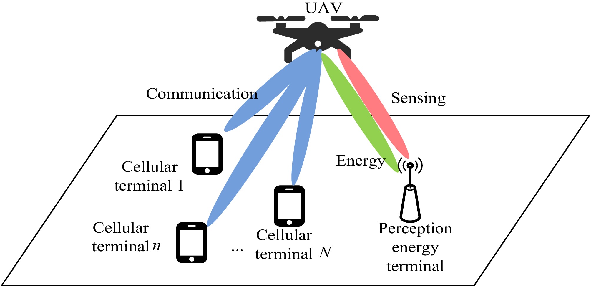
Figure 1.
EAU-ISAC scenario.
The ISAC base station adopts UAVs that can be quickly and flexibly used. Multi-antenna UAVs are equipped with both communication and perception transceiver modules. Among them, the UAV is equipped with M linear uniform antenna arrays, denoted as BUAV. To receive wireless energy transmission from ground energy stations, UAVs are equipped with corresponding RF energy coupling modules. The N single antenna communication modules on the ground are denoted as Cn, n = 1, 2, ..., N. The ground energy station is mainly used for wireless charging of UAVs, denoted as BEH. As an important part of the system, the ground energy station is also equipped with a sensing function module, which is used to sense the position, speed, and other information of the drone, so as to better complete the wireless transmission of energy and other functions.
In the energy harvesting-assisted UAV sensor integration system shown in Fig. 2, a sensor integration transmission protocol based on EH technology is proposed. A system transmission cycle T is divided into three time slots, represented by τ1T, τ2T, and τ3T respectively.
$ {\tau _1}T{\text{ + }}{\tau _2}T{\text{ + }}{\tau _3}T{\text{ = }}T $ (1) We assume that τ = {τ1, τ2, τ3}, one of the most important factors in this transmission protocol, is to allocate the length τ of the three time slots reasonably, to achieve the best resource allocation efficiency. In the first time slot τ1T, where 0 < τ1 < 1, the ground perception energy station BEH wirelessly charges UAV BUAV. In the second time slot τ2T, where 0 < τ2 < 1, UAV UAV BUAV sends communication signals xc to N single antenna ground terminals. In the third time slot τ3T, where 0 < τ3 < 1, the UAV UAV BUAV sends a sensing signal xs to the ground sensing energy station UAV BEH.
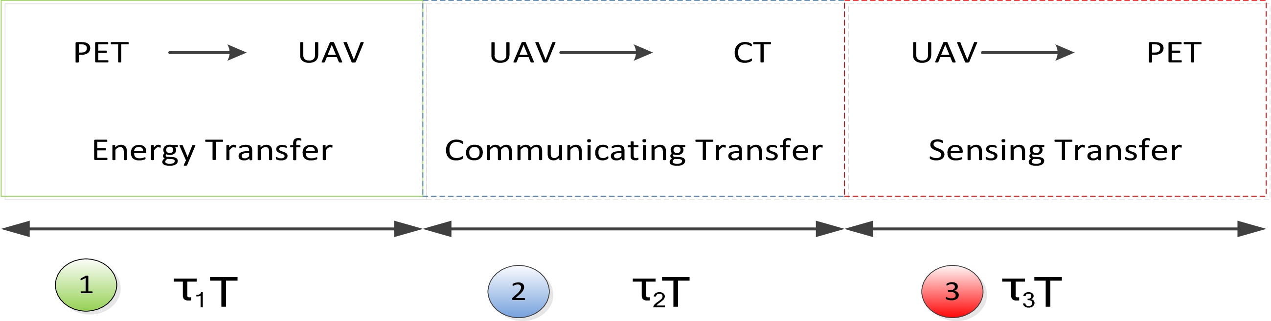
Figure 2.
EAU-ISAC protocol.
Energy harvesting model
-
The total energy EUAV collected by the UAV in the first time slot is represented as:
$ {E_{UAV}} = \eta {\tau _1}T{P_E}\sum\limits_{i = 1}^M {h_{i,1}^{EU}} $ (2) where,
$\eta $ $ \eta $ $ h_{i,1}^{EU} $ $h_{i,1}^{EU}\sim CN(0,\sigma _{EU\left( {i,1} \right)}^2)$ $ \sigma _{EU\left( {i,1} \right)}^2 $ In the first time slot, the UAV harvests enough energy EUAV to support the transmission of communication signals and perception signals in the following two time slots. Dividing the energy consumption of the system into three parts: UAV total energy consumption PU, cellular terminal total energy consumption PC, and perception terminal total energy consumption PS. The total energy consumption of the system can be expressed as:
$ {P^{total}} = {P^U} + {P^C} + {P^S} $ (3) Among them, the total energy consumption PU of UAV is divided into three parts: communication module power consumption
$ P_{com}^u $ $ P_{sen}^u $ $ P_{inh}^u $ $ {P^U} = P_{com}^u + P_{sen}^u + P_{inh}^u $ (4) Among them, the power consumption
$ P_{com}^u $ $ P_{sen}^u $ $ P_{com}^u = \sum _{n = 1}^N{\left\| {{\boldsymbol{\omega}} _n^c} \right\|^2} $ (5) $ P_{sen}^u = \sum _{n' = 1}^N{\left\| {{\boldsymbol{\omega}} _{n'}^s} \right\|^2} $ (6) The inherent power consumption
$ P_{inh}^u $ $ P_{inh}^u = P_{mov}^u + P_{ho}^u $ (7) where,
$ P_{mov}^u $ $ P_{ho}^u $ Communication model
-
In the second time slot, the UAV BS sends communication signals to the ground sensing integrated terminal.
$s_n^c$ $n$ $\omega _n^c \in {\mathbb{C}^{N \times 1}}$ $ {{\boldsymbol{x}}_c} = \sum\limits_{n = 1}^N {{\boldsymbol{\omega}} _n^cs_n^c} $ (8) Assuming
$s_n^c$ $s_n^c \sim \mathcal{C}\mathcal{N}\left( {0,1} \right)$ $ P_{tran}^{u2} $ $ P_{tran}^{u2} = \mathbb{E}\left( {{{\left\| {{{\boldsymbol{x}}_c}} \right\|}^2}} \right) = \sum _{n = 1}^N{\left\| {{\boldsymbol{\omega}} _n^c} \right\|^2} $ (9) As shown in the Cartesian coordinate system in Fig. 1, assuming the flight altitude of the drone is h0, the coordinates of the drone are denoted as (x, y, h0), where u = (x,y) represents its horizontal coordinates.
The integrated ground sensing terminals are all located on a horizontal plane. The coordinates of
$n \in N$ Considering that UAVs serve as aerial base stations and their altitude generally does not change, this paper does not study the optimization of UAV altitude, but only the optimization of its horizontal position. UAV base stations usually hover in open positions, so we establish a Line of Sight (LOS) channel. The channel gain
$ {h_n}\left( {u,{c_n}} \right) \in {\mathbb{C}^{N \times 1}} $ $n$ $ {{\boldsymbol{h}}_n}\left( {{\boldsymbol{u}},{c_n}} \right) = \sqrt {\alpha {d^{ - 2}}\left( {{\boldsymbol{u}},{{\boldsymbol{c}}_n}} \right)} {\boldsymbol{b}}\left( {{\boldsymbol{u}},{{\boldsymbol{c}}_n}} \right) = \sqrt {\dfrac{\alpha }{{{H^2} + {{\left\| {{\boldsymbol{u}} - {{\boldsymbol{c}}_n}} \right\|}^2}}}} {\boldsymbol{b}}\left( {{\boldsymbol{u}},{{\boldsymbol{c}}_n}} \right) $ (10) Among them, α, d(u, cn), and b(u, cn)
$ \in {\mathbb{C}^{N \times 1}}$ $n$ The signal received by the
$n$ $ {y_n} = {\boldsymbol{h}}_n^H\left( {{\boldsymbol{u}},{{\boldsymbol{c}}_n}} \right){\boldsymbol{x}} + N_n^0 = {\boldsymbol{h}}_n^H\left( {{\boldsymbol{u}},{{\boldsymbol{c}}_n}} \right){\boldsymbol{\omega}} _n^cs_n^c + \sum\limits_{i = 1,i \ne n}^N {{\boldsymbol{h}}_n^H\left( {{\boldsymbol{u}},{{\boldsymbol{c}}_n}} \right){\boldsymbol{\omega}} _i^cs_i^c} + N_n^0 $ (11) Among them,
$N_n^0 \sim \mathcal{C}\mathcal{N}\left( {0,\sigma _n^2} \right)$ After decomposing the received signal using Eq. (4), the SINR of the n-th communication terminal is expressed as:
$ {\text{SIN}}{{\text{R}}_n} = \dfrac{{{{\left| {{\boldsymbol{h}}_n^H\left( {{\boldsymbol{u}},{{\boldsymbol{c}}_n}} \right){\boldsymbol{\omega}} _n^c} \right|}^2}}}{{{{\left| {\displaystyle\sum\limits_{i = 1,i \ne n}^N {{\boldsymbol{h}}_n^H\left( {{\boldsymbol{u}},{{\boldsymbol{c}}_n}} \right){\boldsymbol{\omega}} _i^c} } \right|}^2} + \sigma _n^2}} $ (12) Furthermore, we can provide the total achievable rate of UAV downlink communication as:
$ {R_{total}}({\boldsymbol{u}}{,}\omega _n^c) = \dfrac{1}{2}\sum\limits_{n = 1}^N {{{\log }_2}\left(1 + \dfrac{{{{\left| {{\boldsymbol{h}}_n^H\left( {{\boldsymbol{u}},{{\boldsymbol{c}}_n}} \right){\boldsymbol{\omega}} _n^c} \right|}^2}}}{{{{\left| {\displaystyle\sum\limits_{i = 1,i \ne n}^N {{\boldsymbol{h}}_n^H\left( {{\boldsymbol{u}},{{\boldsymbol{c}}_n}} \right){\boldsymbol{\omega}} _i^c} } \right|}^2} + \sigma _n^2}}\right)} $ (13) Perception model
-
In the third time slot, the UAV aerial base station sends a sensing signal to the ground sensing energy station BEH.
ss represents the expected perception signal sent by the drone to the ground sensing integrated terminal.
$\omega _m^s \in {\mathbb{C}^{M \times 1}}$ $ {{\boldsymbol{x}}_s} = \sum\limits_{m = 1}^M {{\boldsymbol{\omega}} _m^ss_m^s} $ (14) Assuming
$ s_m^s $ $s_m^s \sim \mathcal{C}\mathcal{N}\left( {0,1} \right)$ $ P_{tran}^{u3} $ $ P_{tran}^{u3} = \mathbb{E}\left( {{{\left\| {{{\boldsymbol{x}}_s}} \right\|}^2}} \right) = \sum _{m = 1}^M{\left\| {{\boldsymbol{\omega}} _m^s} \right\|^2} $ (15) The ground perception energy station BEH is located in the horizontal plane and its coordinates are represented as (xs, ys, 0), where s = (xs, ys) represents its horizontal coordinates.
Similar to the signals received by communication terminals, the signals received by ground perception energy station BEH for perception and monitoring can be represented as:
$ {y_s} = \sum\limits_{m = 1}^M {{{\boldsymbol{g}}^H}\left( {{\boldsymbol{u}},{\boldsymbol{s}}} \right){\boldsymbol{\omega}} _m^ss_m^s} + N_s^0 = {{\boldsymbol{g}}^H}\left( {{\boldsymbol{u}},{\boldsymbol{s}}} \right){\boldsymbol{\omega}} _n^cs_i^c + \sum\limits_{m = 1}^M {{{\boldsymbol{g}}^H}\left( {{\boldsymbol{u}},{\boldsymbol{s}}} \right){\boldsymbol{\omega}} _m^ss_m^s} + N_s^0 $ (16) Similarly, the perceived channel gain can be expressed as:
$ {\boldsymbol{g}}\left( {{\boldsymbol{u}},{\boldsymbol{s}}} \right) = \sqrt {{\alpha _s}{d_s}^{ - 2}\left( {{\boldsymbol{u}},{\boldsymbol{s}}} \right)} {{\boldsymbol{b}}_s}\left( {{\boldsymbol{u}},{\boldsymbol{s}}} \right) \in {\mathbb{C}^{N \times 1}} $ (17) Among them, αs, ds(u, s), and bs(u, s)
$ \in {\mathbb{C}^{N \times 1}}$ $N_s^0 \sim \mathcal{C}\mathcal{N}\left( {0,\sigma _n^2} \right)$ Therefore, the monitoring signal-to-noise ratio of ground perception energy station BEH can be written as:
$ {\text{SINR}}_n^s = \dfrac{{{{\left| {{{\boldsymbol{g}}^H}\left( {{\boldsymbol{u}},{\boldsymbol{s}}} \right){\boldsymbol{\omega}} _n^c} \right|}^2}}}{{{{\left| {\displaystyle\sum\limits_{m = 1}^M {{{\boldsymbol{g}}^H}\left( {{\boldsymbol{u}},{\boldsymbol{s}}} \right){\boldsymbol{\omega}} _m^s} } \right|}^2} + \sigma _s^2}} $ (18) Problem modeling
-
This model mainly studies the integrated resource allocation of sensing, considering energy harvesting factors. Therefore, decision variables include time allocation (energy harvesting time τ1T, communication signal transmission time τ2T, perception signal transmission time τ3T), power allocation (communication beamforming vector
$\omega _n^c \in {\mathbb{C}^{N \times 1}}$ $\omega _m^s \in {\mathbb{C}^{M \times 1}}$ $\omega = \left\{ {\omega _n^c,\omega _m^s} \right\}$ This model considers two objectives: communication and perception, and should be a multi-objective optimization model. Regarding communication indicators, we hope to maximize the total achievable rate
${R_{total}}(u{\mathbf{,}}\omega _n^c)$ $ {\text{SINR}}_n^s $ Next, we will analyze the constraints and consider the energy consumption optimization problem of UAVs. Although the inherent power consumption
$ P_{inh}^u $ $ P_{com}^u $ $ P_{sen}^u $ We assume that the maximum transmission power of the UAV is Pmax, and we can obtain the UAV communication and perception power and limitations as follows:
$ \sum _{n = 1}^N{\left\| {{\boldsymbol{\omega}} _n^c} \right\|^2} + \sum _{n' = 1}^N{\left\| {{\boldsymbol{\omega}} _{n'}^s} \right\|^2} \leq {P_{\max }} $ (19) $ {P_{\max }}\left( {{\tau _2} + {\tau _3}} \right) = {E_{UAV}} + E_{UAV}^0 $ (20) Among them,
$ E_{UAV}^0 $ In summary, the resource allocation problem of the EH assisted unmanned aerial vehicle communication perception integrated system is expressed as follows:
$ \begin{gathered} P1: \;\;\;\mathop {\max }\limits_{\tau ,u,\omega } {\text{ }}{R_{total}}({\boldsymbol{u}}{,}\omega _n^c) = \dfrac{1}{2}\sum\limits_{n = 1}^N {{{\log }_2}\left(1 + \dfrac{{{{\left| {{\boldsymbol{h}}_n^H\left( {{\boldsymbol{u}},{{\boldsymbol{c}}_n}} \right){\boldsymbol{\omega}} _n^c} \right|}^2}}}{{{{\left| {\displaystyle\sum\limits_{i = 1,i \ne n}^N {{\boldsymbol{h}}_n^H\left( {{\boldsymbol{u}},{{\boldsymbol{c}}_n}} \right){\boldsymbol{\omega}} _i^c} } \right|}^2} + \sigma _n^2}}\right)} \\ \qquad\;\;\;\mathop {\max }\limits_{\tau ,u,\omega } {\text{ min SINR}}_n^s = \dfrac{{{{\left| {{{\boldsymbol{g}}^H}\left( {{\boldsymbol{u}},{\boldsymbol{s}}} \right){\boldsymbol{\omega}} _n^c} \right|}^2}}}{{{{\left| {\displaystyle\sum\limits_{m = 1}^M {{{\boldsymbol{g}}^H}\left( {{\boldsymbol{u}},{\boldsymbol{s}}} \right){\boldsymbol{\omega}} _m^s} } \right|}^2} + \sigma _s^2}} \\ \quad s.t.\;{\text{ C1:}}\sum _{n = 1}^N{\left\| {{\boldsymbol{\omega}} _n^c} \right\|^2} + \sum _{n' = 1}^N{\left\| {{\boldsymbol{\omega}} _{n'}^s} \right\|^2} \leqslant {P_{\max }} \\ \qquad\;\;\; C2:{\tau _1}{\text{ + }}{\tau _2}{\text{ + }}{\tau _3}{\text{ = 1}} \\ \qquad\;\;\; C3:{P_{\max }}\left( {{\tau _2} + {\tau _3}} \right) = {E_{UAV}} + E_{UAV}^0 \\ \end{gathered} $ (21) where, C1 represents the energy consumption constraint condition of the UAV system. C2 is the time constraint condition for UAV systems.
-
Optimization problem P1 is a multi-objective optimization problem, and in the actual solving process, one optimization objective can be transformed into a constraint condition, with a focus on the optimization problem of the other optimization objective. This model transforms communication metrics into constraints and instead studies the perception performance of the system.
Here we make a reasonable approximation to transform the maximum achievable rate
${R_{total}}({\boldsymbol{u}}{\mathbf{,}}\omega _n^c)$ ${R_n}({\boldsymbol{u}}{, }\omega _n^c)$ $ {R_n}({\boldsymbol{u}}{,}\omega _n^c) = \dfrac{1}{2}{\log _2}\left(1 + \dfrac{{{{\left| {{\boldsymbol{h}}_n^H\left( {{\boldsymbol{u}},{{\boldsymbol{c}}_n}} \right){\boldsymbol{\omega}} _n^c} \right|}^2}}}{{{{\left| {\displaystyle\sum\limits_{i = 1,i \ne n}^N {{\boldsymbol{h}}_n^H\left( {{\boldsymbol{u}},{{\boldsymbol{c}}_n}} \right){\boldsymbol{\omega}} _i^c} } \right|}^2} + \sigma _n^2}}\right) \geqslant {R_{\min }} $ (22) Thus, the new optimization problem P2 can be expressed as:
$ \begin{gathered} P2: \quad\mathop {\max }\limits_{\tau ,u,\omega } {\text{ min SINR}}_n^s = \dfrac{{{{\left| {{{\boldsymbol{g}}^H}\left( {{\boldsymbol{u}},{\boldsymbol{s}}} \right){\boldsymbol{\omega}} _n^c} \right|}^2}}}{{{{\left| {\displaystyle\sum\limits_{m = 1}^M {{{\boldsymbol{g}}^H}\left( {{\boldsymbol{u}},{\boldsymbol{s}}} \right){\boldsymbol{\omega}} _m^s} } \right|}^2} + \sigma _s^2}} \\ \quad s.t.\;{\text{ C1:}}\sum _{n = 1}^N{\left\| {{\boldsymbol{\omega}} _n^c} \right\|^2} + \sum _{n' = 1}^N{\left\| {{\boldsymbol{\omega}} _{n'}^s} \right\|^2} \leq {P_{\max }} \\ \qquad\;\;\;C2:{\tau _1}+ {\tau _2} +{\tau _3} = 1 \\ \qquad\;\;\;C3:{P_{\max }}\left( {{\tau _2} + {\tau _3}} \right) = {E_{UAV}} + E_{UAV}^0 \\ \qquad\;\;\;C4:{R_n}({\boldsymbol{u}}{,}\omega _n^c) = \dfrac{1}{2}{\log _2}\left(1 + \dfrac{{{{\left| {{\boldsymbol{h}}_n^H\left( {{\boldsymbol{u}},{{\boldsymbol{c}}_n}} \right){\boldsymbol{\omega}} _n^c} \right|}^2}}}{{{{\left| {\displaystyle\sum\limits_{i = 1,i \ne n}^N {{\boldsymbol{h}}_n^H\left( {{\boldsymbol{u}},{{\boldsymbol{c}}_n}} \right){\boldsymbol{\omega}} _i^c} } \right|}^2} + \sigma _n^2}}\right) \geq {R_{\min }} \\ \end{gathered} $ (23) Continuing to analyze optimization problem P2, according to its objective function, P2 is an MM problem. By introducing auxiliary variable A and adding a constraint condition C5, the MM problem can be transformed into a minimax problem, which can be rephrased as:
$ \begin{gathered} P3: \;\;\;\mathop {\max }\limits_{\tau ,u,\omega } {\text{ }}A \\ \quad s.t.{\text{ C1 : }}\sum _{n = 1}^N{\left\| {{\boldsymbol{\omega}} _n^c} \right\|^2} + \sum _{n' = 1}^N{\left\| {{\boldsymbol{\omega}} _{n'}^s} \right\|^2} \leq {P_{\max }} \\ \qquad\;\; C2:{\tau _1} + {\tau _2}+ {\tau _3} = 1 \\ \qquad\;\; C3:{P_{\max }}\left( {{\tau _2} + {\tau _3}} \right) = {E_{UAV}} + E_{UAV}^0 \\ \qquad\;\; C4:{R_n}({\boldsymbol{u}},\omega _n^c) = \dfrac{1}{2}{\log _2}\left(1 + \dfrac{{{{\left| {{\boldsymbol{h}}_n^H\left( {{\boldsymbol{u}},{{\boldsymbol{c}}_n}} \right){\boldsymbol{\omega}} _n^c} \right|}^2}}}{{{{\left| {\displaystyle\sum\limits_{i = 1,i \ne n}^N {{\boldsymbol{h}}_n^H\left( {{\boldsymbol{u}},{{\boldsymbol{c}}_n}} \right){\boldsymbol{\omega}} _i^c} } \right|}^2} + \sigma _n^2}}\right) \geq {R_{\min }} \\ \qquad\;\; C5:{\text{SINR}}_n^s = \dfrac{{{{\left| {{{\boldsymbol{g}}^H}\left( {{\boldsymbol{u}},{\boldsymbol{s}}} \right){\boldsymbol{\omega}} _n^c} \right|}^2}}}{{{{\left| {\displaystyle\sum\limits_{m = 1}^M {{{\boldsymbol{g}}^H}\left( {{\boldsymbol{u}},{\boldsymbol{s}}} \right){\boldsymbol{\omega}} _m^s} } \right|}^2} + \sigma _s^2}} \geq A,n \in N \\ \end{gathered} $ (24) The new optimization problem P3 contains three decision variables. To simplify the expression, we assume τ1 = τ and τ2 = τ3, and the length of the second and third time slots is (1 − τ)T/2. Upon careful observation of problem P3, the simplified time decision variable τ has no coupling relationship with the power allocation factor
$\omega = \left\{ {\omega _n^c,\omega _m^s} \right\}$ $\omega $ $ \begin{gathered} P4: \;\;\;\mathop {\max }\limits_{u,\omega } {\text{ }}A \\ \quad\; s.t.{\text{ C1:}}\sum _{n = 1}^N{\left\| {\omega _n^c} \right\|^2} + \sum _{m = 1}^M{\left\| {\omega _m^s} \right\|^2} \leq {P_{\max }} \\ \qquad\;\;\;C4:{R_n}(u{\mathbf{,}}\omega _n^c) = \dfrac{1}{2}{\log _2}\left(1 + \dfrac{{{{\left| {h_n^H\left( {u,{c_n}} \right)\omega _n^c} \right|}^2}}}{{{{\left| {\displaystyle\sum\limits_{i = 1,i \ne n}^N {h_n^H\left( {u,{c_n}} \right)\omega _i^c} } \right|}^2} + \sigma _n^2}}\right) \geq {R_{\min }} \\ \qquad\;\;\;C5:{\text{SINR}}_n^s = \dfrac{{{{\left| {{g^H}\left( {u,s} \right)\omega _n^c} \right|}^2}}}{{{{\left| {\displaystyle\sum\limits_{m = 1}^M {{g^H}\left( {u,s} \right)\omega _m^s} } \right|}^2} + \sigma _s^2}} \geq A,n \in N \\ \qquad\;\;\;C6:{P_{\max }}\left( {1 - {\tau ^*}} \right) = {E_{UAV}} + E_{UAV}^0 \\ \end{gathered} $ (25) Optimization of the algorithm for the beamforming vector under a fixed UAV position
-
Given the position u of the drone, the optimization subproblem of the beamforming vector set
$\mathop {\omega = \left\{ {\omega _n^c,\omega _m^s} \right\}}\nolimits_{n = 1,2,...,N,}^{m = 1,2,..,M} $ $ \begin{gathered} {\text{P5}}:\mathop {\max }\limits_\omega A \\ {\text{ s}}{\text{.t}}{\text{. C1,C4,C5,C6}} \\ \end{gathered} $ (26) Analyzing the constraints of optimization problem P5, it can be found that constraint C1, C4−C5 contains quadratic variables
$\left\{ {\omega _n^c} \right\}_{n = 1}^N$ $\left\{ {\omega _m^s} \right\}_{m = 1}^M$ $W_n^c \triangleq \omega _n^c{\left[ {\omega _n^c} \right]^{\text{H}}} $ $n \in N$ $W_m^s \triangleq \omega _m^s{\left[ {\omega _m^s} \right]^{\text{H}}} $ $ m \in M$ $ \text{Rank}\left(W_n^c\right)=1,\ n\in N $ (27) $ \text{Rank}\left(W_m^s\right)=1,\ m\in M $ (28) Thus, problem P5 can be transformed into:
$ \begin{gathered} {\text{P6}}:\mathop {\max }\limits_{W_n^c,W_m^s} A \\ \;\; s.t.{\text{ }} C6:{P_{\max }}\left( {1 - {\tau ^*}} \right) = {E_{UAV}} + E_{UAV}^0 \\ \qquad C7:\sum\limits_{n = 1}^N {{\text{tr}}\left( {{\boldsymbol{W}}_n^c} \right)} + \sum\limits_{m = 1}^M {{\text{tr}}\left( {{\boldsymbol{W}}_m^s} \right)} \leq {P_{\max }} \\ \qquad C8:{R_n}({\boldsymbol{u}},{\boldsymbol{W}}_n^c) = \dfrac{1}{2}{\log _2}(1 + \dfrac{{{\text{tr}}\left( {{{\boldsymbol{h}}_n}\left( {{\boldsymbol{u}},{{\boldsymbol{c}}_n}} \right){\boldsymbol{h}}_n^H\left( {{\boldsymbol{u}},{{\boldsymbol{c}}_n}} \right){\boldsymbol{W}}_n^c} \right)}}{{\displaystyle\sum\limits_{i = 1,i \ne n}^N {{\text{tr}}\left( {{{\boldsymbol{h}}_n}\left( {{\boldsymbol{u}},{{\boldsymbol{c}}_n}} \right){\boldsymbol{h}}_n^H\left( {{\boldsymbol{u}},{{\boldsymbol{c}}_n}} \right){\boldsymbol{W}}_i^c} \right)} + \sigma _n^2}}) \geq {R_{\min }} \\ \qquad C9:{\text{SINR}}_n^s = \dfrac{{{\text{tr}}\left( {{{\boldsymbol{g}}_n}\left( {{\boldsymbol{u}},{{\boldsymbol{c}}_n}} \right){\boldsymbol{g}}_n^H\left( {{\boldsymbol{u}},{{\boldsymbol{c}}_n}} \right){\boldsymbol{W}}_n^c} \right)}}{{{\text{tr}}\left( {{{\boldsymbol{g}}_n}\left( {{\boldsymbol{u}},{{\boldsymbol{c}}_n}} \right){\boldsymbol{g}}_n^H\left( {{\boldsymbol{u}},{{\boldsymbol{c}}_n}} \right){\boldsymbol{W}}_m^s} \right) + \sigma _s^2}} \geq A,n \in N \\ \qquad C10:{\text{rank}}\left( {{\boldsymbol{W}}_n^c} \right) \leq 1,n \in N \\ \qquad C11:{\text{rank}}\left( {{\boldsymbol{W}}_m^s} \right) \leq 1,m \in M \\ \end{gathered} $ (29) After a series of convex optimization processes in this section, if we ignore the rank one constraint of the optimization problem P6, we can use common convex optimization methods, such as the CVX toolbox, or use intelligent optimization algorithms or machine learning methods for optimization. It should be noted that after using Eigen Value Decomposition (EVD), it is necessary to verify the rank one problem, that is, the feasibility of the solution.
In summary, the beamforming vector optimization algorithm under a fixed UAV position is shown in Algorithm 1 below.
Table 1. The optimization algorithm for the beamforming vector under a fixed UAV position.
1. Initialization: Set the iteration termination number $ N_P^{max} $, iteration termination accuracy $ {\varepsilon _P} $, and iteration initial values $W_n^c,\forall n$ and $\omega _m^s,\forall m$. 2. Loop body: 3. Update iteration index i = i + 1; 4. Solve the optimization problem $ F({q_i}) = \mathop {\max }\limits_{W_n^c,W_m^s} A $ and obtain $ \left\{ {W_n^{c*},W_m^{s*}} \right\} $; 5. Perform EVD decomposition on $ W_n^{c*} $ and $ W_m^{s*} $, and calculate $w_n^c,\forall n$ and $w_m^s,\forall m$ under the current iteration index; 6. End condition: $ \left| {F({q_i}) - F({q_{i - 1}})} \right| < {\varepsilon _P} $ or $ i > N_P^{max} $. 7. Output the optimal solution $ \left\{ {{q^*},W_n^{c*},W_m^{s*}} \right\} $. Position optimization algorithm under a fixed UAV beamforming vector
-
After the beamforming vector
$\left\{ {\omega _n^c,\forall n,\omega _m^s,\forall m} \right\}$ $u$ $ \begin{gathered} {\text{P7}}:\mathop {\max }\limits_u A \\ {\text{ s}}{\text{.t}}{\text{. C4,C5}} \\ \end{gathered} $ (30) Adopting a trust region based continuous convex approximation optimization algorithm, the constraints C4 and C5 are first processed.
By transforming C4, we can obtain:
$ \left( {{2^{2{R_{\min }}}} - 1} \right)\left( {{{\left| {\sum\limits_{i = 1,i \ne n}^N {{\boldsymbol{h}}_n^H\left( {{\boldsymbol{u}},{{\boldsymbol{c}}_n}} \right){\boldsymbol{\omega}} _i^c} } \right|}^2} + \sigma _n^2} \right) \geq {\left| {{\boldsymbol{h}}_n^H\left( {{\boldsymbol{u}},{{\boldsymbol{c}}_n}} \right){\boldsymbol{\omega}} _n^c} \right|^2} $ (31) Define
$ {\boldsymbol{W}}_i^c = {\boldsymbol{\omega}} _n^c{\left[ {{\boldsymbol{\omega}} _n^c} \right]^{\text{H}}} $ ${\boldsymbol{W}}_j^s = {\boldsymbol{\omega}} _m^s{\left[ {{\boldsymbol{\omega}} _m^s} \right]^{\text{H}}}$ $ \left( {{2^{2{R_{\min }}}} - 1} \right)\left( {\sum\limits_{i = 1,i \ne n}^N {\left. {\left( {{\boldsymbol{W}}_i^c,d({\boldsymbol{u}},{{\boldsymbol{c}}_n})} \right.} \right)} + \sigma _n^2} \right) \geq \left. {\left( {{\boldsymbol{W}}_n^c,d({\boldsymbol{u}},{{\boldsymbol{c}}_n})} \right.} \right) $ (32) Using the same method, C5 removes the denominator and obtains:
$ \left|\boldsymbol{g}^H\left(\boldsymbol{u},\boldsymbol{s}\right)\boldsymbol{\omega}_n^c\right|^2\ge A\left(\left|\sum\limits_{m=1}^M\boldsymbol{g}^H\left(\boldsymbol{u},\boldsymbol{s}\right)\boldsymbol{\omega}_m^s\right|^2+\sigma_s^2\right),\ n\in N $ (33) Further transformation of C5 yields:
$ \left. {\left( {{\boldsymbol{W}}_n^c,d({\boldsymbol{u}},{{\boldsymbol{c}}_n})} \right.} \right) \geq A\left( {\sum\limits_{m = 1}^M {\left( {\left. {{\boldsymbol{W}}_m^s,d({\boldsymbol{u}},{{\boldsymbol{c}}_n})} \right)} \right.} + \sigma _s^2} \right),\; n \in N $ (34) Based on the above processing, problem P7 can be transformed into an approximately convex problem P8:
$ \begin{gathered} {\text{P}}8:\mathop {\max }\limits_u A \\ \quad\;\;\; s.t.{\text{ C12:}}\left( {{2^{2{R_{\min }}}} - 1} \right)\left( {\sum\limits_{i = 1,i \ne n}^N {\left. {\left( {{\boldsymbol{W}}_i^c,d({\boldsymbol{u}},{{\boldsymbol{c}}_n})} \right.} \right)} + \sigma _n^2} \right) \geq \left. {\left( {{\boldsymbol{W}}_n^c,d({\boldsymbol{u}},{{\boldsymbol{c}}_n})} \right.} \right) \\ \qquad\quad C13:\left. {\left( {{\boldsymbol{W}}_n^c,d({\boldsymbol{u}},{{\boldsymbol{c}}_n})} \right.} \right) \geq A\left( {\sum\limits_{m = 1}^M {\left( {\left. {{\boldsymbol{W}}_m^s,d({\boldsymbol{u}},{{\boldsymbol{c}}_n})} \right)} \right.} + \sigma _s^2} \right), \;n \in N \\ \end{gathered} $ (35) Considering the accuracy and efficiency of UAV position optimization, we set the iteration accuracy. As long as the iteration accuracy is set small enough, the convergence of the optimization algorithm can always be ensured. The specific optimization algorithm is shown in Algorithm 2, which gives the optimal UAV position under a fixed beamforming vector.
Table 2. UAV position optimization algorithm under a fixed beamforming vector.
1. Initialization: Set the iteration termination number $ N_u^{max} $, iteration termination accuracy $ {\varepsilon _u} $, and iteration initial values u. 2. Loop body: 3. Update iteration index i = i + 1; 4. Solve the optimization problem F(qi) = $ \mathop {\max }\limits_u A $ and obtain u*; 5. Analyze the position information of u* and calculate the UAV position
(x, y, h0) under the current iteration index;6. End condition: | F(qi) − F(qi−1) | < ${\varepsilon _u} $ or i > $N_u^{max} $. 7. Output the optimal solution {q*, u*}. Joint optimization algorithm for beamforming and position based on UAV energy harvesting
-
In the earlier sections, Algorithm 1 solved the optimal beamforming vector
$ \left\{ {W_n^{c*},W_m^{s*}} \right\} $ Table 3. UAV position optimization algorithm under a fixed beamforming vector.
1. Initialization: Set the termination times $ N_{outer}^{max} $ and $ N_{inner}^{max} $ for the outer loop and inner loop, as well as the termination precision $ {\varepsilon _{outer}} $ and $ {\varepsilon _{inner}} $ 2. External circulation body : 3. Set the initial values q0 = 0 and n = 0 for the outer loop; 4. Using binary method to solve the optimal energy harvesting time slot allocation factor τ; 5. Internal circulation body 1: 6. Set the iteration termination number $ N_P^{max} $, iteration termination accuracy $ {\varepsilon _P} $, and iteration initial values $W_n^c,\forall n$ and $\omega _m^s,\forall m$; 7. Run Algorithm 1 to solve the optimization problem and run F(qi) = $ \mathop {\max }\limits_{W_n^c,W_m^s} A $. 8. Output the optimal solution $ \left\{ {{q^*},W_n^{c*},W_m^{s*}} \right\} $; 9. End condition of inner loop 1: | F(qi − F(qi−1) | < $ {\varepsilon _P} $ or i > $ N_P^{max} $ 10. Internal circulation body 2: 11. Set the iteration termination number $ N_u^{max} $, iteration termination accuracy $ {\varepsilon _u} $, and iteration initial value u; 12. Run Algorithm 2 to solve the optimization problem F(qi) = $ \mathop {\max }\limits_u A $; 13. Output the optimal solution {q*, u*}; 14. End condition for inner loop 2: | F(qi) − F(qi−1) | < $ {\varepsilon _u} $ or i > $ N_u^{max} $. 15. Calculate F(q) = $ \mathop {\max }\limits_{\tau ,u,\omega } A $ and update q; 16. End condition of outer loop: | qn − qn−1) | < $ {\varepsilon _{outer}} $ or n > $ N_{outer}^{max} $. 17. Output the optimal solution {q*, τ*, u*, $ \omega ^* $} and obtain the joint resource allocation scheme for the energy harvesting assisted UAV sensing integration system. -
This study employs MATLAB for Monte Carlo simulations. The simulation encompasses an area of 1 km × 1 km, equipped with N = 4 communication terminals and one ground sensing terminal. Four communication terminals are situated at (250, 250, 0), (250, 750, 0), (750, 250, 0), and (750, 750, 0). The ground sensing terminal is located at (500, 500, 0). The UAV flight altitude H = 100 m with the number of antennas M = 4. UAV maximum transmission power pmax = 0.3 W. There is also a threshold for the sensing terminal
$SINR_{\min }^3 $ $ \sigma _n^2 = \sigma _s^2 $ As shown in Fig. 3, with the increase of transmission power PA, both the algorithm proposed in this paper and the algorithms in previous research studies[9−11] can significantly improve the perceptual spectrum performance. The difference is that the joint optimization algorithm proposed in this paper for EH time slots, UAV positions, and beamforming vectors performs the best. Although Yang & Gursoy[9] did not consider EH time slot allocation, they jointly optimized UAV positioning and beamforming, achieving the second-best performance. Sun et al.[10] focused on UAV positioning with equal power allocation, while Wen et al.[11] optimized only power allocation without considering UAV positioning, resulting in the worst performance among the three. The position optimization of UAVs is more cost-effective than power allocation.
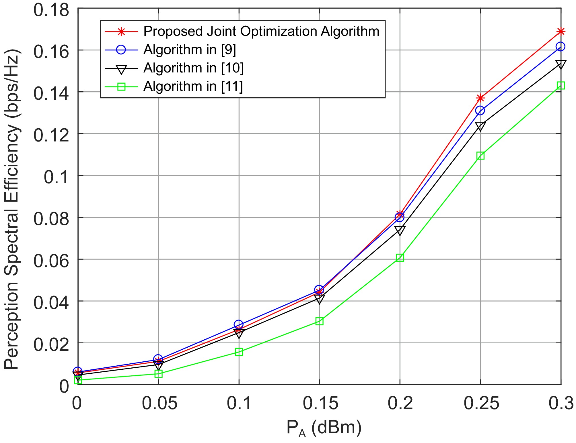
Figure 3.
Perceived spectral efficiency with N = 4 and M = 4.
As shown in Fig. 4, the overall performance curve is consistent with that in Fig. 3. We are considering a larger number of array antennas, M = 16. The use of large-scale antennas can improve the system's perceptual spectrum performance. However, as the transmission power PA increases, this improvement in performance gain gradually decreases.
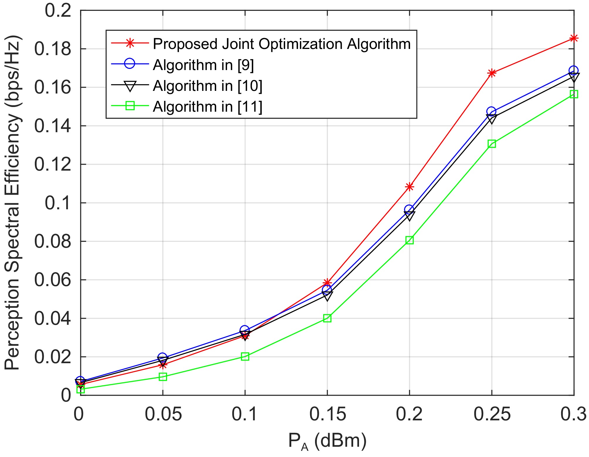
Figure 4.
Perceived spectral efficiency with N = 4 and M = 12.
As shown in Fig. 5, we focus on the relationship between the number of array antennas and the perceived spectral efficiency of the system from another perspective. It is not difficult to find that the larger the number of antennas, the better the perceived spectrum performance. However, as the number of antennas increases from 4 to 8, there is a significant improvement in system performance. However, as the number of antennas further increases, the gain in perceived spectrum performance gradually decreases. This indicates that blindly increasing the number of large-scale antennas is not ideal.
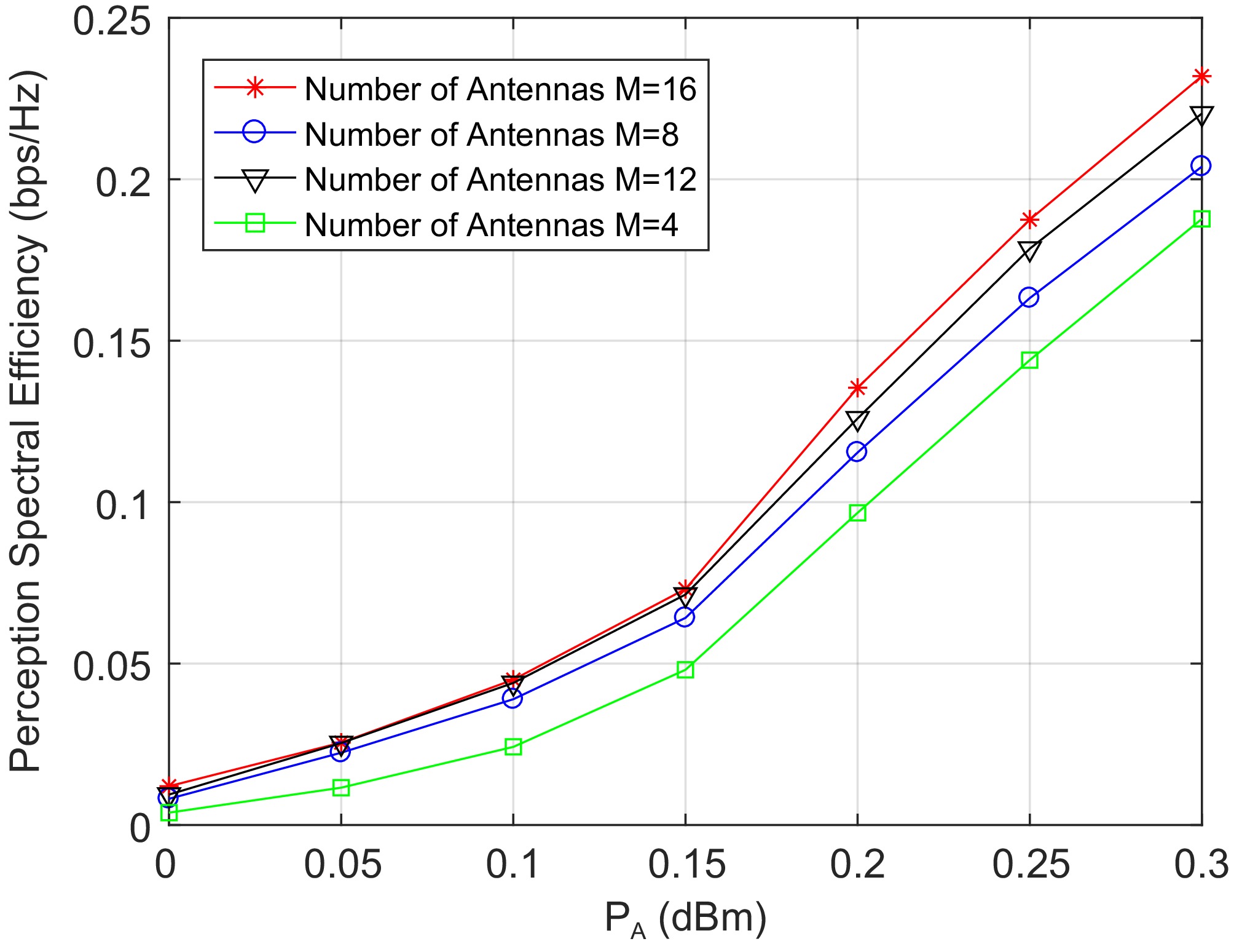
Figure 5.
Relationship between perceived spectrum efficiency and number of antenna.
-
This paper focuses on the integration of UAV communication and perception with energy harvesting assistance, and proposes an innovative joint optimization algorithm aimed at maximizing the minimum perception performance while ensuring communication user performance standards by optimizing the UAV's launch beamforming and flight position. Given the crucial role of energy harvesting in maintaining unmanned aerial vehicles for prolonged mission execution, this paper first considers the optimization problem of energy harvesting time slots. By introducing the binary search method, it effectively solves the problem of how to allocate time reasonably for energy harvesting within limited flight time, to ensure that drones have sufficient energy support when performing communication and perception tasks. Given the position of the drone, further exploration was conducted on how to improve system performance by optimizing the transmission beamforming vector. The SDP technology has successfully transformed the complex beamforming optimization problem into a solvable convex optimization problem, thereby optimizing perception performance while ensuring communication quality. Given the optimal beamforming vector, the original non-convex position optimization problem is transformed into a series of easily solvable convex optimization subproblems using SCA technology. By iteratively solving these sub problems, this paper gradually approaches the global optimal solution and achieves precise optimization of the drone's position. This step not only improves the perception performance of the system but also enhances the flexibility and adaptability of the drone when performing complex tasks. In the future, ISAC-UAV research will be more in-depth, and the direction of energy optimization and time efficiency optimization may be very valuable.
This study was supported by the Outstanding Young Backbone Teachers Program of "Qinglan Project" in Jiangsu Higher Education Institutions, the Open Project of the State Key Laboratory of Southeast University (K93-9-2024-04), the Major Project of Basic Science (Natural Science) Research in Jiangsu Higher Education Institutions (23KJA520004), the General Projects of Philosophy and Social Sciences Research in Jiangsu Higher Education Institutions (2024SJYB0346, 2024SJYB0344), the Action Plan of the National Engineering Research Center for Cybersecurity Level Protection and Security Technology (KJ-24-004), and the Research Project on Degree and Postgraduate Education and Teaching Reform of Jiangsu Province (JGKT24_B036, JGKT23_C051).
-
The authors confirm their contributions to the paper as follows: conceptualization, validation: Liang G, Xu H; methodology, software, formal analysis, data curation, writing, visualization: Liang G; investigation: Liu X; resources: Xu H; supervision, project administration, funding acquisition: Chen C. All authors have read and agreed to thepublished version of the manuscript.
-
All data analysed or used in this study are are contained within the published paper.
-
The authors declare that they have no conflict of interest.
- Copyright: © 2026 by the author(s). Published by Maximum Academic Press, Fayetteville, GA. This article is an open access article distributed under Creative Commons Attribution License (CC BY 4.0), visit https://creativecommons.org/licenses/by/4.0/.
-
About this article
Cite this article
Liang G, Xu H, Liu X, Chen C. 2026. Energy harvesting assisted UAV sensing integrated system resource allocation. Wireless Power Transfer 13: e002 doi: 10.48130/wpt-0025-0020 

Energy harvesting assisted UAV sensing integrated system resource allocation
- Received: 13 September 2024
- Revised: 15 November 2024
- Accepted: 25 November 2024
- Published online: 14 January 2026
Abstract: In the context of the deep integration of wireless communication and perception technology, this paper examines the resource allocation problem of an energy harvesting-assisted unmanned aerial vehicle (UAV) communication and perception integrated systems. Firstly, an energy harvesting-assisted UAV sensing integrated system was constructed, which consists of a sensing integrated base station, sensing terminals, and ground sensing energy stations. Then, based on the separate study of energy consumption models, communication models, and perception models, an integrated energy harvesting-assisted UAV sensing system model was established. Considering the optimization objectives of communication and perception, communication metrics were transformed into constraints and the research focussed on studying the perception performance of the system. A series of convex optimization methods were used to solve the conversion optimization problem, and the optimal energy harvesting time slot allocation was solved using the binary method. The established optimization model takes into account the deep coupling between the drone beamforming vector and the position decision variable. Finally, the optimal solution was obtained through alternating iterations using semi-definite programming (SDP), the Dinkelbach method, and the successful convex approximation (SCA) method. The simulation experiment fully verifies the effectiveness of the proposed algorithm.
-
Key words:
- Energy /
- Harvesting /
- UAV /
- Sensing /
- Integrated