


-
With the development of technological intelligence, and the improvement of people's living standards, the demand for electrical energy in production and daily life has become increasingly prominent[1]. Currently, the mainstream power transmission method remains wired transmission, but this method faces issues such as line aging, difficult wiring in complex terrains, and high maintenance costs[2]. As a key technology to overcome the limitations of traditional cable connections, wireless power transmission (WPT) technology is profoundly changing the way energy is acquired and utilized.
Overview of existing WPT technologies and their limitations
-
Current mainstream WPT technologies can be categorized based on their transmission mechanisms, with their key performance metrics and application boundaries summarized in Table 1. Electromagnetic induction WPT, widely used in near-field scenarios, such as electric vehicle charging pads and smartwatch chargers, relies on magnetic flux linkage between primary and secondary coils[3]. However, its transmission distance is typically limited to 0−10 cm; beyond this range, magnetic flux leakage causes energy attenuation of over 90%, making it unsuitable for medium- to long-distance applications[4]. Magnetic resonance coupling WPT improves transmission distance to 0.1–5 m by leveraging resonant frequency matching between coils, but it is highly sensitive to coil alignment, and environmental interference[5]. Microwave/radiowave WPT, which transmits energy via electromagnetic wave radiation, can achieve kilometer-level transmission, but its energy conversion efficiency is extremely low (usually < 10%) due to spherical wave divergence, and it poses potential electromagnetic interference risks to communication systems[6].
Table 1. Comparison of mainstream WPT technologies.
WPT technology Transmission distance Energy attenuation Conversion efficiency Key limitations Electromagnetic induction 0–10 cm > 90% 85%–95% Ultra-short distance, high flux leakage Magnetic resonance coupling 0.1–5 m 50%–80% 60%–80% Sensitive to alignment, environmental interference Microwave/radiowave 1–100 km > 99% < 10% Low efficiency, electromagnetic interference Single-Wire Power Transmission (SWPT) 50 m–1 km 5%–15% 80%–95% Dependence on single-wire medium, limited theoretical validation Research gaps and unique advantages of SWPT
-
Against this backdrop, SWPT emerges as a promising alternative for medium- to long-distance energy transfer. Early SWPT studies date back to Tesla's 1900 patent, which proposed using a single wire and earth as a loop to transmit power[7]. However, Tesla's work lacked quantitative analysis of electromagnetic fields, and failed to identify the energy carrier. Subsequent research by Meyl proposed that scalar waves might be the energy carrier in SWPT, but his experiments only validated 100-m-level transmission without systematic simulation verification of field distribution[8]. The team of Professor Xiyou Chen from Dalian University of Technology achieved 90% efficiency in 50-m SWPT using an inductance-resistance equivalent model, but their analysis focused on circuit-level performance rather than the fundamental wave propagation mechanism[9].
Compared with the aforementioned mainstream WPT technologies and existing SWPT studies, the unique advantages of the SWPT system analyzed in this study are twofold:
(1) Low Attenuation and Long Distance: Unlike microwave WPT's severe spherical divergence, the single wire constrains electromagnetic field propagation to the vicinity of the wire, resulting in only 5%–15% energy attenuation at 200 m, which is far lower than magnetic resonance coupling's 80% attenuation at 5 m.
(2) Simplified Structure: Compared with multi-coil resonance systems, SWPT uses only a single wire as the transmission medium, reducing hardware complexity and maintenance costs by 40%–60%.
However, SWPT also has inherent limitations that need to be addressed. SWPT requires a physical single wire (such as copper or aluminum conductors) as the transmission medium, and thus cannot fully replace 'medium-free' technologies such as microwave wireless power transmission. Meanwhile, previous studies have not clearly verified the scalar wave mechanism; some scholars argue that the performance of single-wire power transmission can be explained by traditional transverse electromagnetic (TEM) waves, leading to ongoing controversies in the academic community[10].
Research objectives and contributions
-
In view of the above research gaps (unclear energy carrier mechanism of SWPT, lack of systematic comparison with mainstream WPT), and the technology's unique advantages, this paper focuses on the SWPT system. First, it sorts out the typical SWPT system structures proposed by Tesla, Meyl, and others, and clarifies the core role of the single wire in each system. Second, combined with the derivation of Maxwell's wave equations, it analyzes the possibility that the energy carrier in SWPT propagates in the form of scalar waves, distinguishing it from the TEM wave mechanism of traditional WPT. Finally, a simulation model is built using Comsol software to observe the distribution of electromagnetic fields on the single wire and verify its scalar wave characteristics. This study not only provides theoretical support for clarifying the SWPT principle but also establishes a performance comparison framework between SWPT and existing WPT technologies, guiding the selection of appropriate WPT solutions for specific application scenarios.
-
The research on SWPT technology can be traced back to Tesla's patent in 1900[6,7], as shown in the Fig. 1. The left side is the transmitting device, and the right side is the receiving device. A and B are the secondary coil and primary coil of the transmitting end, respectively, where coil A is used for voltage boosting, and coil B is connected to the power supply. A' and B' are the secondary coil and primary coil of the receiving end respectively, where coil A' is used for voltage reduction, and coil B' is connected to the load.
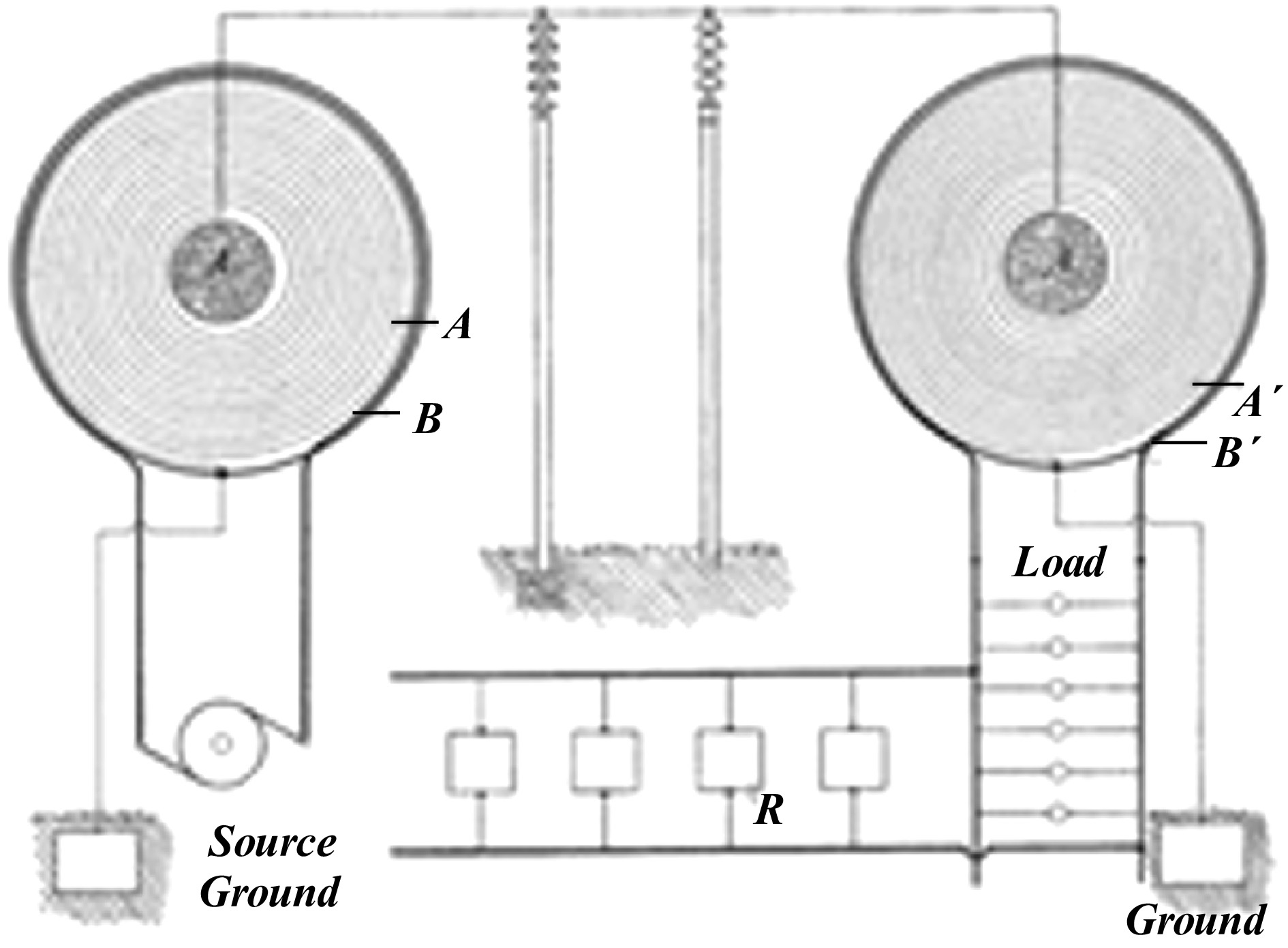
Figure 1.
Tesla single wire system structure.
In the circuit proposed by Tesla, an excitation is applied across the primary coil B at the transmitting end, and the voltage is boosted by coil A. The energy is transmitted to the secondary coil A' at the receiving side through a single wire, then reduced in voltage and transmitted to coil B', and finally output to both ends of the load to complete the energy flow. In this structure, the secondary coils of the transmitting end and the receiving end are connected by a wire to form a loop, and the other ends of coils A and A' are grounded respectively. Ideally, the earth is a good conductor, and can also be regarded as a loop. The two loops form a cyclic structure to realize power transmission. Therefore, the above circuit can be simplified, as shown in Fig. 2[10].
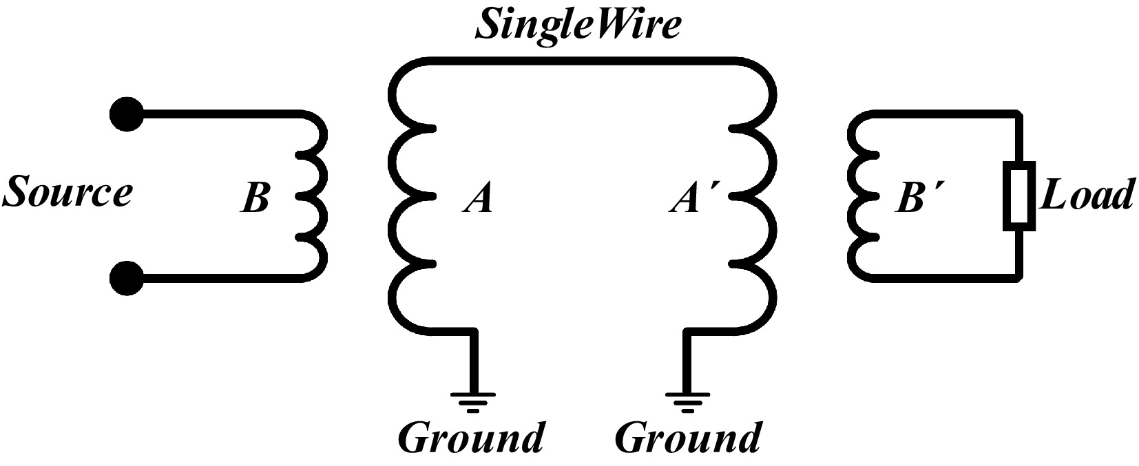
Figure 2.
Tesla single wire system equivalent structure diagram.
On this basis, the research team led by Professor Xiyou Chen from Dalian University of Technology (Dalian, China) conducted further in-depth research. They built a more detailed circuit model by using the inductance-resistance equivalent method for the coil, single wire, grounding side, and other parts in the model, and conducted a series of experiments, as shown in Fig. 3. At a distance of 50 m, 200 W light bulbs were lit, with a transmission efficiency of over 90%[9].
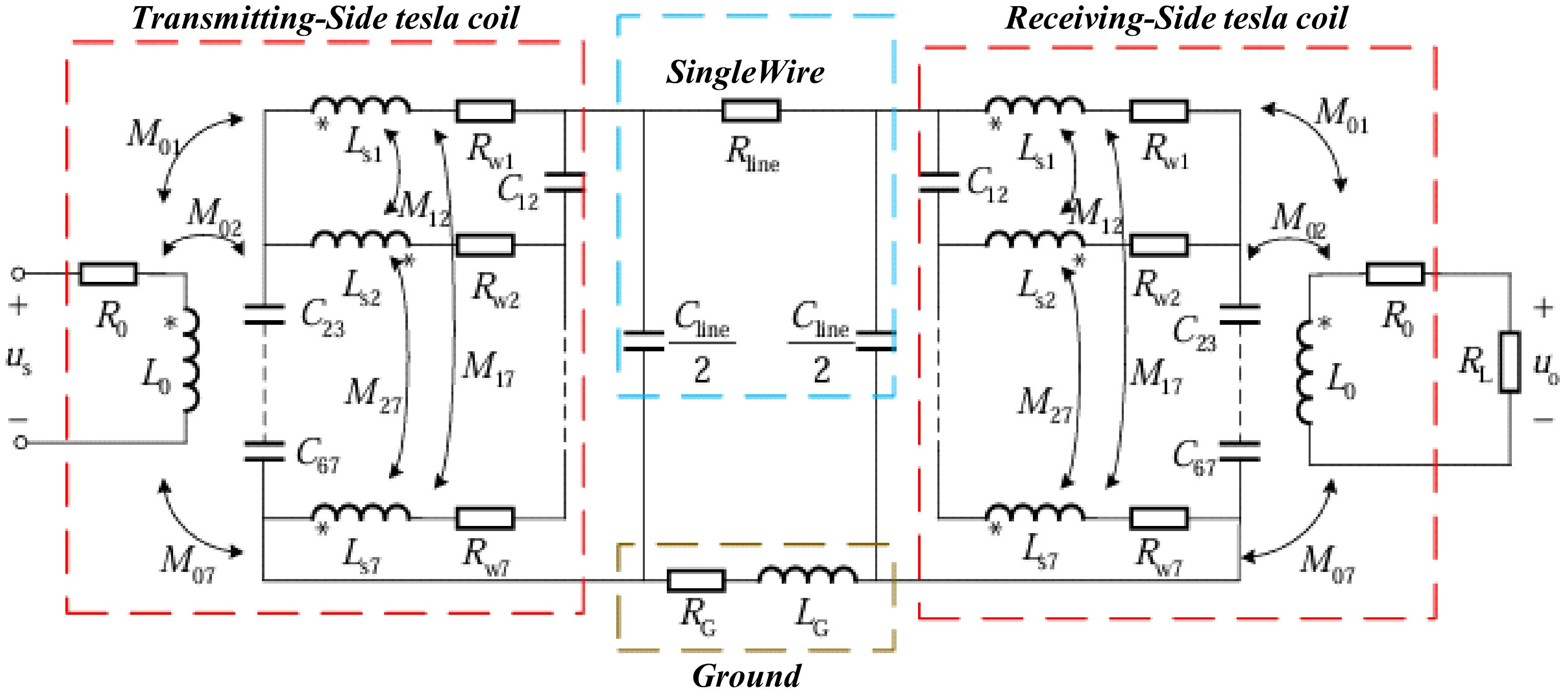
Figure 3.
Detailed structural diagram of single wire power transmission system.
Meyl also conducted a large number of experiments on the SWPT system based on Tesla's patent, and proposed that energy in the SWPT system propagates in the form of scalar waves. By analyzing the closed resonant loop, Meyl disassembled and separated the resonant capacitor and resonant inductor to form a new separated resonant circuit, and finally built a resonant circuit with an open capacitor[8]. Through the continuous transformation of the circuit model, a SWPT system structure with capacitive coupling was built, as shown in Fig. 4.
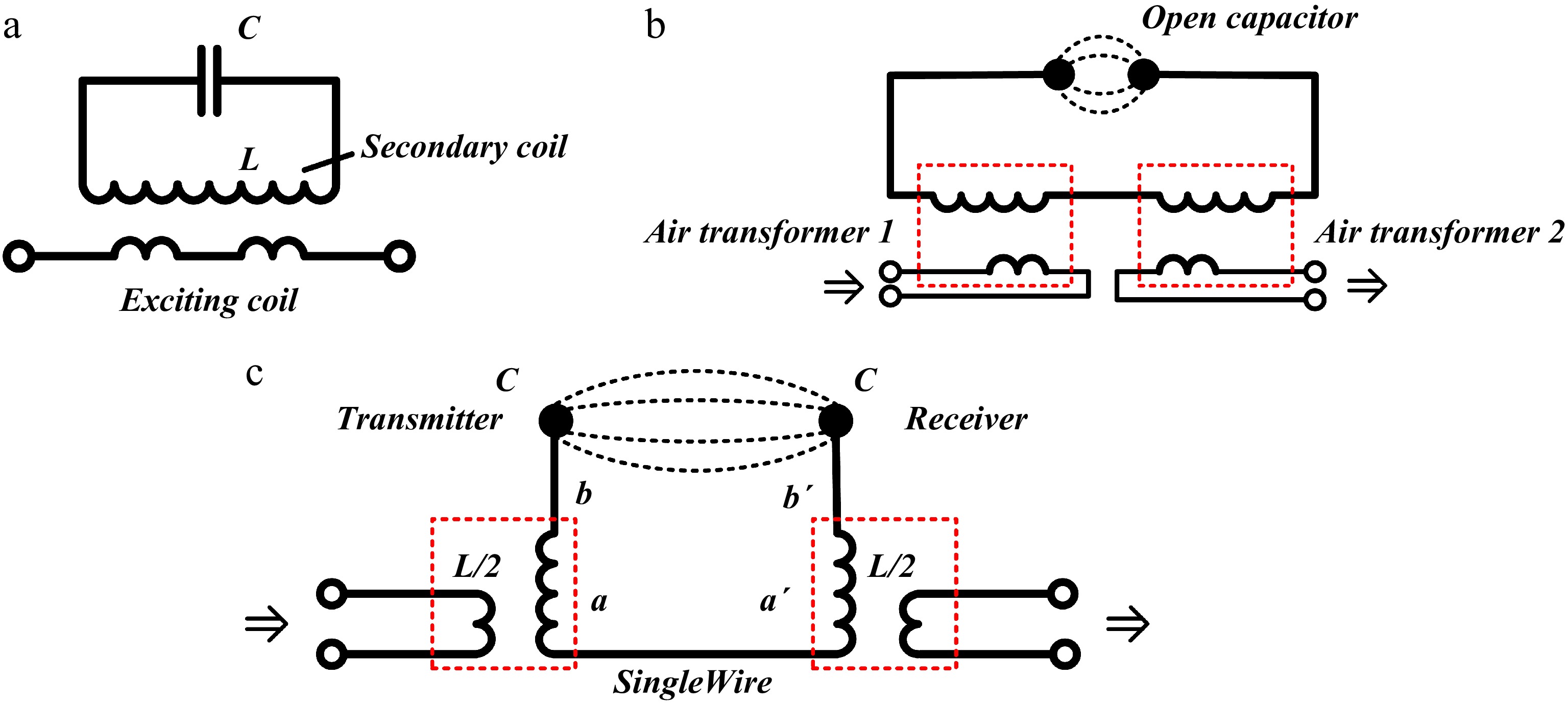
Figure 4.
System structure diagram from Meyl[8]. (a) Closed resonant circuit. (b) Separating the resonant circuit. (c) Resonant circuit with open capacitor.
Figure 4c shows the model of the SWPT system with an open capacitor designed by Meyl[8]. Among them, b and b' are capacitor structures composed of metal spheres, a and a' are the secondary coils at the input and output ends, respectively, and the capacitors and coils are connected through metal rods. One end of the coil is connected to the metal rod, and the other end connects the transmitting and receiving parts through a single-wire structure.
The Wireless Power Transmission Technology Research Institute of Chongqing University (Chongqing, China) designed a single-capacitor coupled wireless power transmission system with bilateral LC compensation, which uses two polar plates, and an LC compensation network for power transmission. The transmitting end and the receiving end are only connected through a single capacitor, and there is no direct electrical connection loop between the two ends. The system structure is shown in Fig. 5[11].
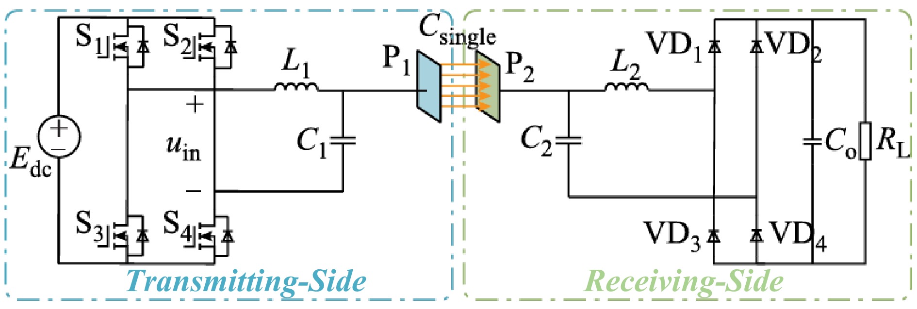
Figure 5.
Single capacitive coupled wireless power transfer system with double-side LC compensation.
The above circuit is simplified, as shown in Fig. 6.
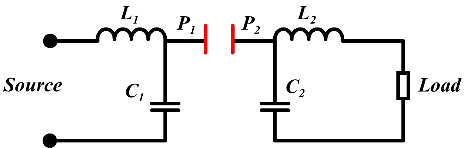
Figure 6.
Single capacitive coupled with double-side LC compensation system simplified diagram.
By comparing the above several SWPT system models, it can be found that the SWPT system proposed by Tesla has a single-wire loop and a common ground loop (which can also be a conductor such as seawater or a metal surface). One end of Meyl's system realizes capacitive coupling through metal spheres, and the other end connects the transmitting end and the receiving end through a single wire to form a loop structure together. The research team of Chongqing University realizes SWPT only through a pair of capacitor plates and uses LC resonance instead of the coupling coil structure. Despite the different circuit structures, they all have a common feature—they are inseparable from a single wire, and the AC power supply and the load are connected through a single wire. Therefore, the present research focus is on the single wire and close attention is paid to the changes of the electric and magnetic fields on the single wire during the power transmission process.
-
From the analysis in the previous section, regardless of the system structure, the single wire is an indispensable part of the power transmission system. It is precisely because of the existence of the single wire that electrical energy can be transmitted directionally from the transmitting end to the receiving end. Therefore, it is necessary to further analyze the distribution of the electric and magnetic fields on the single wire.
In terms of transmission principle, Meyl tried to find the longitudinal wave component from the perspective of Maxwell's wave equation, and then derived the generalized Maxwell equation.
$ \Delta E=grad\;div\;E-rot\;rot\;E=\dfrac{1}{{c}^{2}}\dfrac{{\delta }^{2}E}{\delta {t}^{2}}$ (1) where,
$ \Delta $ $ {c}^{2} $ $ {t}^{2} $ $ \delta $ When
$ grad\;div\;E=0 $ $ -rot\;rot\;E=\dfrac{1}{{c}^{2}}\dfrac{{\delta }^{2}E}{\delta {t}^{2}} $ $ div\;E=0 $ $ grad\;div\;E\neq 0 $ $ rot\;E=0 $ $ div\;E\neq 0 $ 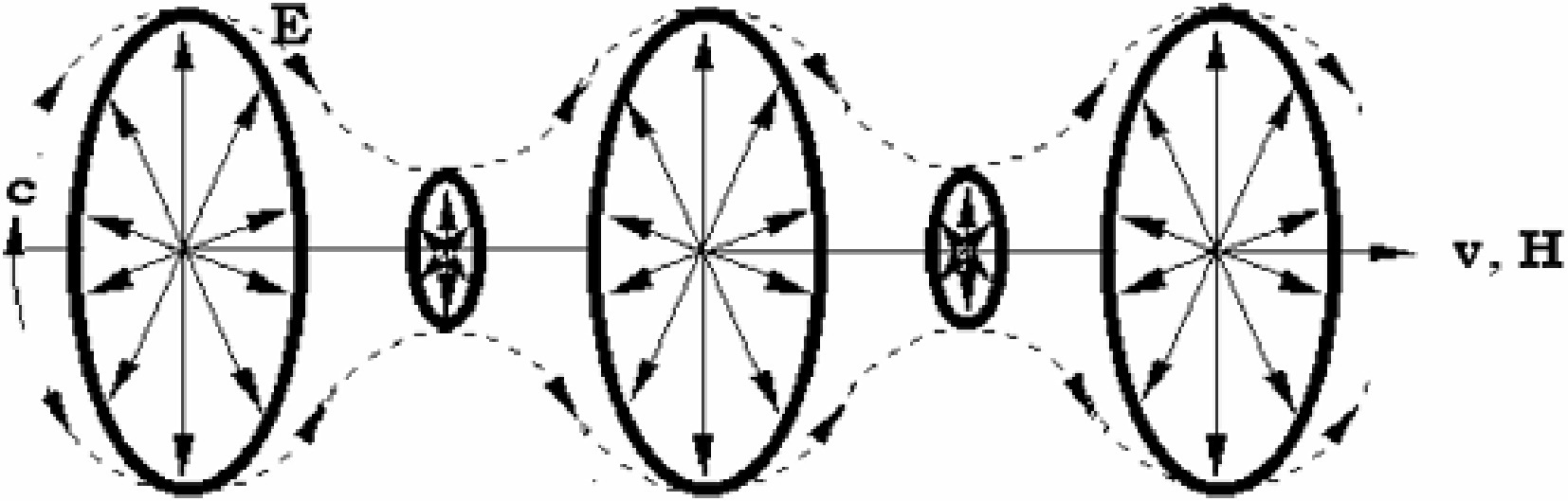
Figure 7.
Electric ring-vortices form a magnetic wave.
The present research focus is on the single wire of the SWPT system. The transmitting end and the receiving end are connected through wire AB, as shown in Fig. 8. When the wire is in a static state, there are a large numbers of free positive and negative charges inside it. When a high-frequency alternating current is applied to the ends A and B of the wire, the high-frequency electromagnetic field will generate a high-frequency induced current on the single wire. However, under high-frequency conditions, the penetration of electric and magnetic fields into good conductors is very low, and most of the fields are only concentrated on the surface of the good conductor, similar to the electrostatic induction phenomenon.
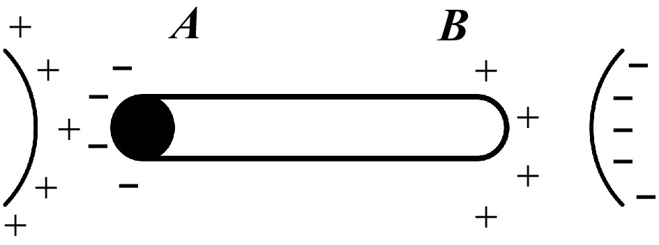
Figure 8.
Electrostatic induction phenomenon diagram.
In the single-wire transmission system, the electromagnetic field is predominantly confined to the region external to the single conductor. Notably, the time-varying electric field in this external region can induce a current, which is primarily manifested in the form of displacement current. The mathematical formulation of displacement current is expressed as follows:
$ {I}_{D}=\dfrac{d{\Phi }_{D}}{dt}=\int \dfrac{\partial D}{\partial t}\cdot dS$ (2) where, ID: Displacement current;
$ {\text{Φ}}_{\text{D}} $ $ \dfrac{\partial D}{\partial t} $ $ {I}_{D}> 0 $ $ {I}_{D}< 0 $ According to the boundary conditions on the surface of an ideal conductor, the displacement current linear density K on the surface of the single wire is related to the magnetic field strength, that is:
$ K={e}_{n}\times \mathrm{H} $ (3) where, K: Displacement current surface density; en: Unit normal vector; H: Magnetic field strength
Among them en is the unit vector in the direction of the outer normal of the single wire surface, and H is the magnetic field strength on the surface of the single wire.
The classical Maxwell wave equation can be expressed as:
$ \nabla \times E=-\dfrac{\partial B}{\partial t}=\dfrac{\rho }{{\epsilon }_{0}}$ (4) $ \nabla \times B={\mu }_{0}J+{\mu }_{0}{\epsilon }_{0}\dfrac{\partial E}{\partial t}$ (5) $ \nabla \times H=J+{\epsilon }_{0}\dfrac{\partial E}{\partial t}=J+\dfrac{\partial D}{\partial t} $ (6) $ \nabla \times D=\rho $ (7) where,
$ \nabla $ $ {\mu }_{0} $ $ {\epsilon }_{0} $ $ \rho $ When the influence of the source is not considered in the system, that is, the system is in an electrostatic field or a quasi-electrostatic field, then
$ \nabla \times E=0 $ $ {\nabla }^{2}u=\dfrac{1}{{c}^{2}}\dfrac{{\partial }^{2}u}{\partial {t}^{2}} $ (8) where,
$ {\nabla }^{2} $ $ u $ Among them,
$ {\nabla }^{2}=\dfrac{{\partial }^{2}}{{\partial x}^{2}}+\dfrac{{\partial }^{2}}{{\partial y}^{2}}+\dfrac{{\partial }^{2}}{{\partial z}^{2}} $ By combining Eqs (4)–(8), the general form of Maxwell's wave equation can be obtained, that is:
$ {\nabla }^{2}E=\dfrac{1}{{c}^{2}}\dfrac{{\partial }^{2}E}{\partial {t}^{2}} $ (9) After simplification, we can get:
$ \nabla\left\{\mathrm{\mathit{E}}\left(x,y,z,t\right)\right\}=\dfrac{1}{c^2}\dfrac{\partial^2\mathrm{\mathit{E}}\left(x,y,z,t\right)}{\partial t^2} $ (10) From the analysis of Eq. (10), when the system is in an electrostatic field or a quasi-electrostatic field, the wave direction of the electromagnetic wave may exist on the x, y, and z axes during the power transmission process. That is, the system may have a longitudinal wave solution, where the wave direction is consistent with the propagation direction, and the wave presents a sparse distribution characteristic. Waveforms of transverse and longitudinal waves, as shown in Figs 9 and 10.
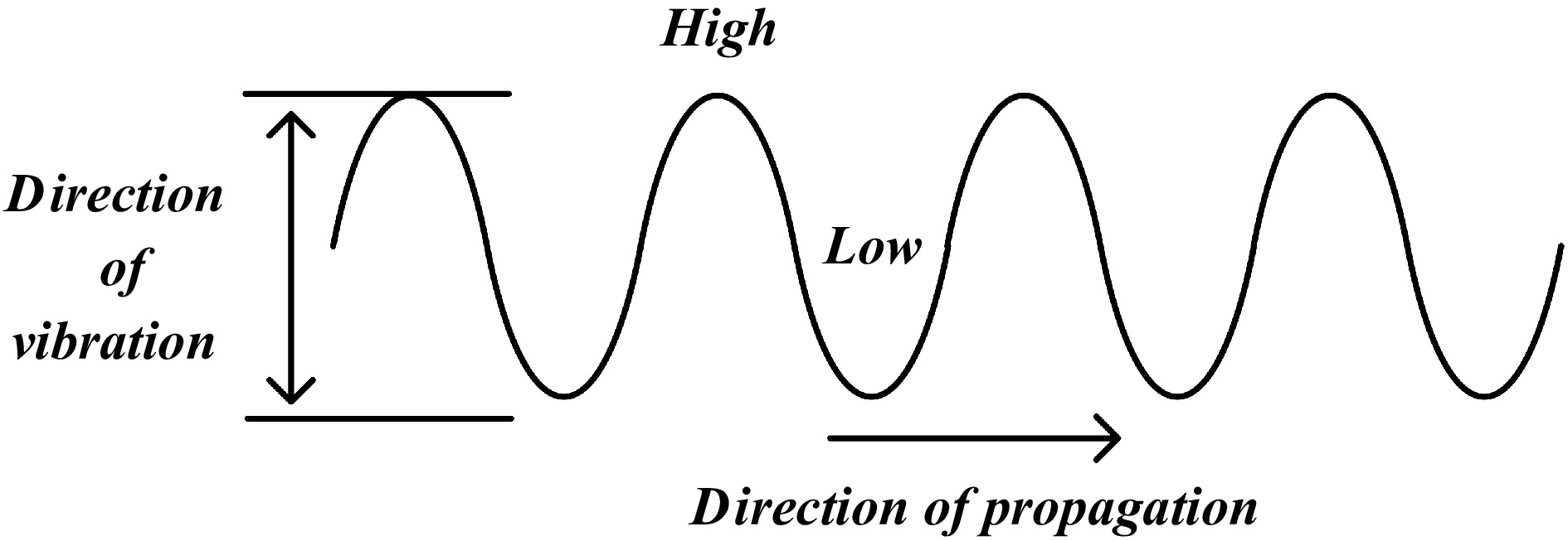
Figure 9.
Basic characteristics of transverse wave propagation.
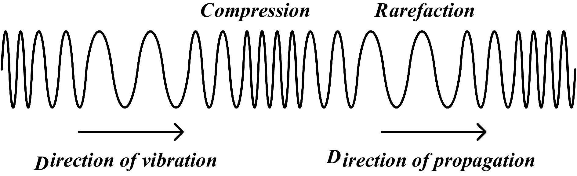
Figure 10.
Basic characteristics of longitudinal wave propagation.
Combined with the spatial theory of electromagnetic fields, when the power supply transmits the electromagnetic field to the free space, if the radiated electromagnetic field is not constrained, it will propagate around the free space, the energy obtained by the receiving side will decrease sharply, and the transmission efficiency will decrease.
Through the above analysis, we can know that in the SWPT system, the current on the single wire mainly exists in the form of displacement current on the surface of the single wire. At the same time, an environment similar to a quasi-electrostatic field is formed for power transmission. Combined with the research content of Meyl and others, we believe that the distribution of the electromagnetic field on the single wire has the characteristic of longitudinal wave distribution in the propagation direction, and the magnetic field distribution around the single wire presents a periodic variation characteristic, as shown in Fig. 11.
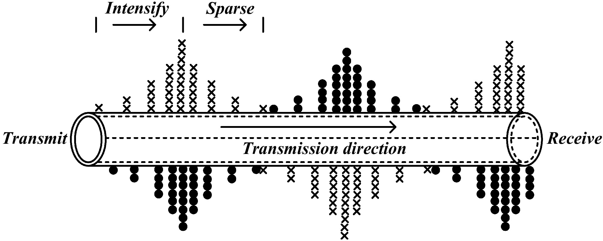
Figure 11.
Magnetic field distribution diagram of single wire electrical energy transmission.
By observing the characteristics of its magnetic field distribution, and combining with the analysis of different SWPT structures above, it can be clearly seen that there is no conductor loop in the SWPT system, and there is no need for conductors such as the earth and seawater to form a loop to complete the power transmission. Instead, the single wire is used as a spatial medium for transmission. From a microscopic perspective, the positive and negative charges move cyclically periodically under the condition of input high-frequency inversion; from a macroscopic perspective, due to the existence of displacement current on the entire wire, the current is conducted from the transmitting end to the receiving end in the form of longitudinal waves along the direction of the wire, which is consistent with the longitudinal wave conduction mode of scalar waves (the power transmission direction is consistent with the change direction). Therefore, we believe that when using this circuit for power transmission, the wave in the wire is likely to be a scalar wave.
-
Based on the analysis of the SWPT theory in the previous section, Comsol was used to simulate the single-wire structure in the SWPT system. The specific device is shown in Fig. 12.The specific parameter information is provided in Table 2.
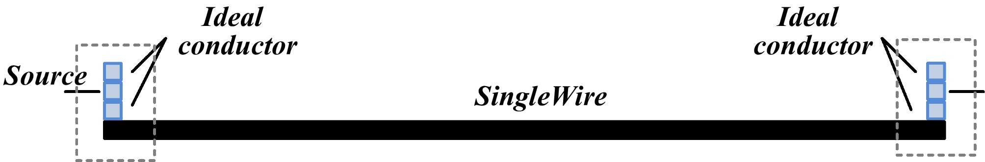
Figure 12.
Schematic diagram of single wire experimental apparatus.
Table 2. Model parameters.
Module name Parameter Length of single wire 200 m Radius of single conductor 0.53 mm Input voltage 100 V Load 50 Ω A high-frequency AC signal to the single-wire input part and connected a load to the receiving end, and simulated the magnetic field and electric field, respectively. The relevant parameters are as follows:
A 100 V high-frequency power supply was input, and the distribution characteristics of the magnetic field and electric field on the single-wire structure were observed, as shown in Figs 13 and 14.
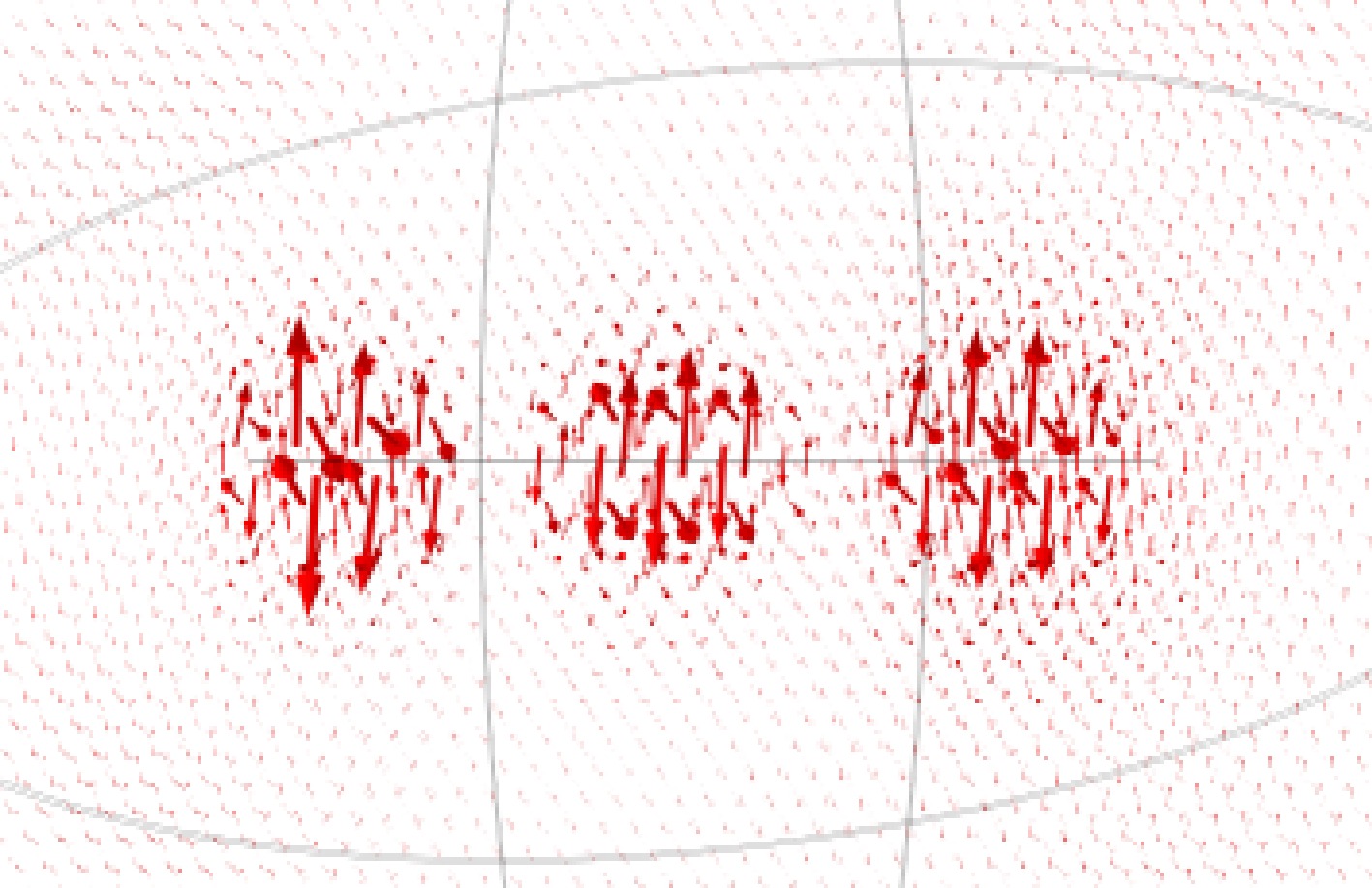
Figure 13.
Single wire magnetic field distribution characteristics.
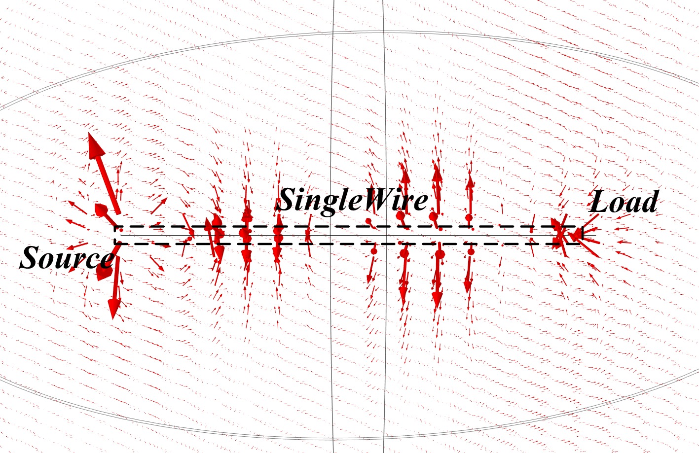
Figure 14.
Single wire electric field distribution characteristics.
From the Comsol simulation diagram, we can clearly see that in the magnetic field distribution diagram of the single-wire structure, the magnetic field distribution along the single-wire structure shows a sparse periodic distribution characteristic from the transmitting end to the output end, which is similar to the characteristic of longitudinal waves. By observing the electric field distribution curve, the electric field distribution characteristic shows a periodic change of expansion – contraction – expansion along the single-wire structure. Through the simulation of the electric and magnetic fields of the single-wire structure, it can be found that the simulation results are very close to Meyl's theory. There may be a longitudinal wave component in the single wire, which is likely to be the energy carrier in the SWPT.
When conducting system simulations, the factors that may affect the distribution characteristics of electric and magnetic fields on the single-wire structure could include the length of the single wire and the voltage across its two ends. The distribution characteristics of magnetic and electric fields on the single-wire structure were tested under different conditions, respectively, as shown in Figs 15, 16, 17, and 18.
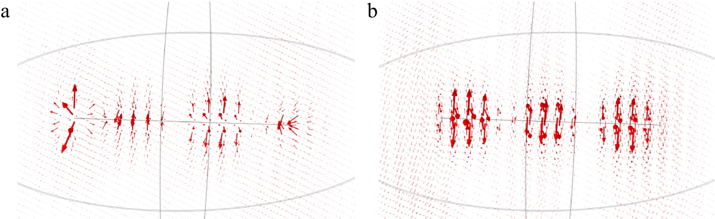
Figure 15.
Electric and magnetic field distribution characteristics of a 200-m single-wire system at 75 V. (a) Electric field distribution. (b) Magnetic field distribution.
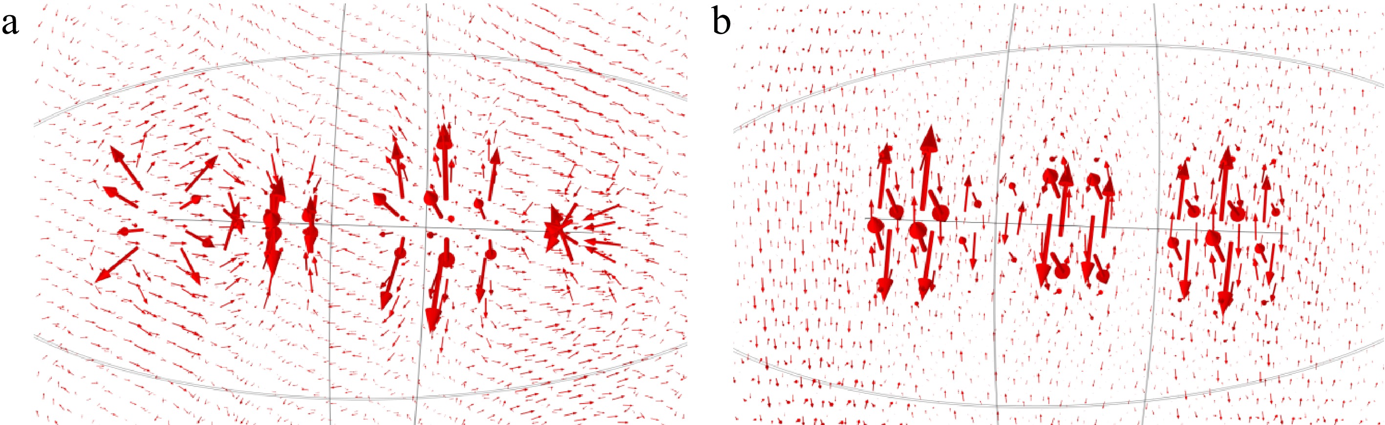
Figure 16.
Electric and magnetic field distribution characteristics of a 200-m single-wire system at 125 V. (a) Electric field distribution. (b) Magnetic field distribution.
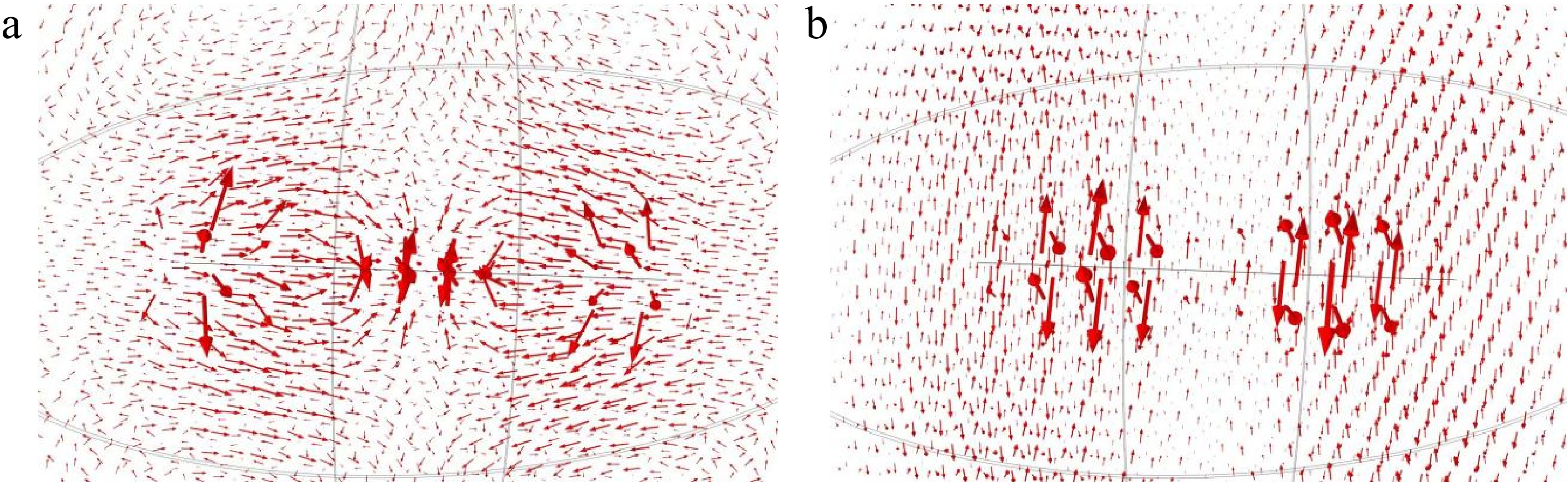
Figure 17.
Electric and magnetic field distribution characteristics of a 150-m single-wire system at 100 V. (a) Electric field distribution. (b) Magnetic field distribution.
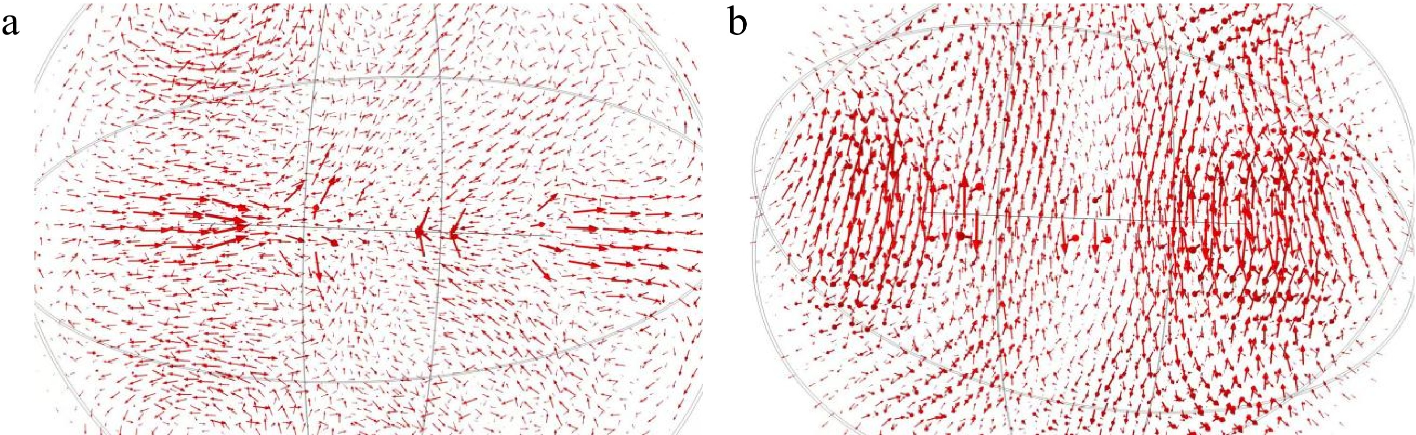
Figure 18.
Electric and magnetic field distribution characteristics of a 220-m single-wire system at 100 V. (a) Electric field distribution. (b) Magnetic field distribution.
By altering the single-wire length, and the input voltage across its two ends in simulations and observing the distribution characteristics of electric and magnetic fields, it can be found that when the single-wire length is fixed, the intensity of the magnetic and electric fields around the single wire increases with the rise of the input voltage across its two ends. When the input voltage across the two ends of the single wire remains constant, the intensity of the magnetic and electric fields around the single wire decreases to a certain extent as the single-wire length increases. However, regardless of changes in the single-wire length or the input voltage across its two ends, the longitudinal wave characteristics of the electric and magnetic fields on the single wire, namely the sparse-dense alternating distribution feature, still persist.
-
This study focuses on the SWPT system, with emphasis on the energy transmission on the single-wire structure in the SWPT system. By sorting out the typical SWPT structures proposed by Tesla, Mely, the team of Professor Chen Xiyou from Dalian University of Technology, and the Wireless Power Transmission Team of Chongqing University, the core role of the single wire in each system is clarified. From the theoretical level, combined with Professor Meyl's derivation of Maxwell's wave equation, it is analyzed that under the condition of an electrostatic field or a quasi-electrostatic field, the single-wire system may have a longitudinal wave solution, the current of the single wire is mainly displacement current, and the electromagnetic field distribution presents the characteristic of longitudinal wave, so it is inferred that the energy carrier may be a scalar wave. From the experimental simulation level, verified by Comsol simulation, under the conditions of setting the single-wire parameters (length 200 m, radius 0.53 mm), inputting 100 V high-frequency voltage, and 50 Ω load, the magnetic field of the single wire shows a sparse periodic distribution, and the electric field shows a periodic change of expansion – contraction. The simulation results are consistent with Meyl's theory, which further confirms that there may be scalar waves in the SWPT, and provides theoretical and experimental support for the development of long-distance wireless power transmission technology.
-
The authors confirm their contribution to the paper as follows: study conception and design, draft manuscript preparation: Wu X, Xiao J; data collection: Mo Y, Liu Q, Wu N; analysis and interpretation of results: Wu X, Xiao J. All authors reviewed the results, and approved the final version of the manuscript.
-
The datasets generated and analyzed during the current study are available from the corresponding author upon reasonable request.
-
Thanks for the support by Guangxi Power Grid Science and Technology Project GXKJXM20240162
-
The authors declare that they have no conflict of interest.
- Copyright: © 2026 by the author(s). Published by Maximum Academic Press, Fayetteville, GA. This article is an open access article distributed under Creative Commons Attribution License (CC BY 4.0), visit https://creativecommons.org/licenses/by/4.0/.
-
About this article
Cite this article
Wu X, Xiao J, Mo Y, Liu Q, Wu N. 2026. Single-wire power transmission principle explanation and simulation analysis. Wireless Power Transfer 13: e017 doi: 10.48130/wpt-0026-0003 

Single-wire power transmission principle explanation and simulation analysis
- Received: 26 October 2025
- Revised: 16 December 2025
- Accepted: 19 December 2025
- Published online: 05 June 2026
Abstract: To resolve controversies over the specific principle of single-wire power transmission (SWPT), this study innovatively confirms the indispensable role of the single wire and identifies scalar waves as the potential energy carrier through structural analysis and simulation. Starting from the typical structure of SWPT systems, it analyzes representative models and verifies that the single wire is a core, irreplaceable component for directional energy transfer. The study further deduces that the energy carrier in SWPT may propagate as scalar waves by exploring electromagnetic field characteristics. Finally, Comsol simulations (200 m single wire, 100 V high-frequency input, 50 Ω load) intuitively show the electric and magnetic field distributions on the single wire, confirming that these fields exhibit the distribution characteristics of scalar waves, providing theoretical and simulation support for clarifying the SWPT principle.
-
Key words:
- Single-wire power transmission /
- Scalar waves /
- Wireless power transfer