


-
To date, a lot of intensive research has been conducted on the combustion and explosion processes of gases in containers and pipes. The explosion characteristics and explosion behavior of sealed containers can be affected by many factors, such as gas concentration, gas composition, initial pressure, and initial temperature. Under different experimental conditions, the explosion hazard can be evaluated by obtaining characteristic parameters such as explosion pressure, maximum rate of pressure rise ((dP/dt)max) and pressure growth index (KG)[1, 2].
$ (dp/dt)_{\max} V^{1/3}=K_G $ (1) Where (dP/dt)max is the maximum explosion pressure rising rate, Pa/s; V is the volume of the container, m3; KG is an explosion severity factor called pressure growth index, Pa·m·s−1. The pressure growth index is an indication of the 'robustness' of the explosion.
There are many studies on the combustion and explosion behavior of flammable mixtures in connected containers. Wang et al.[3] conducted a comparative study on gas explosion in a single container and connected containers and found that the maximum explosion pressure (Pmax) and pressure rising rate in connected containers are higher than those in the single containment container. Maremonti et al.[4] used AutoReaGas software to simulate the explosive capacity of the connected containers and found that both peak pressures and rates of pressure rise are much higher than those generated in single container explosions, and the turbulence induced in both containers represent a major factor affecting the explosion violence. In the experiment on the connected containers where the spherical container and the pipe are connected, it was found that both the size of the pipe, the ignition position, and the initial pressure have greater impact on the explosion of the connected containers, and the changes in the explosion pressure of the containers on both sides were also different[5, 6]. Singh[7] carried out experiments in linked containers with a total volume of 0.07 m3. The results showed that, when the volume ratio, the pipe length and the pipe diameter are constant, the value of the maximum explosion pressure both in the primary container and secondary container increased with the volume of the primary container increasing. In other words, the size effect is very obvious. Razus et al.[8] carried out experiments on the explosion of propylene-air mixtures in two cylindrical containers connected by pipes. The results showed that the initial pressure and the tube diameter are the major factors which influence the explosion evolution in linked containers. Other factors such as the direction of flame propagation, the volume ratio of the primary and secondary containers and the distance between the ignition source and the connecting tube inlet are also important for pressure evolution. According to research carried out by Bartknecht[9], the maximum pressure can be reduced by choosing an appropriate value for the ratio of the pipe cross section to the container volume. Usually, the phenomenon that the gas explosion characteristics change with the size of the container is known as the size effect of the gas explosion characteristics. Benedetto et al.[10, 11] studied the effect of the volume ratio and ignition position of the connected containers on the explosion pressure based on experiments and simulations, and found that the pressure peak intensity is mainly affected by the coupling between the pre-compression of the mixture in the secondary container and the violence of explosion in the same container as related to the venting time. Zhang et al.[12] studied the influence of pipe length on methane-air mixture explosion in linked containers, when the pipe diameter and length was constant, a bigger primary container causes higher initial flame propagation speed, a smaller secondary container caused stronger blocking effect during the flame propagation. Zhen et al.[13] investigated the size effects on a methane–air mixture explosion in the interconnected containers, the maximum rate of pressure rise changed inconspicuously while the secondary container was larger than the primary one, and the cubic-root law was not applicable to an explosion in the interconnected containers. Ogungbemide et al.[14] investigated the effects of varying the length-to-diameter ratio (L/D) of the primary container on pressure piling using numerical modelling, and found that as the L/D of the primary container increased, pressure enhancement in the secondary container (relative to the primary container) increased, and the flame speed in the connected duct decreased, and high frequency oscillations were observed in the extremities of the primary containers. Willacy et al.[15] analyzed the flame propagation and deflagration-detonation transition process through closed and interconnected geometric containers. Roser et al.[16] found from the explosion data that the flame front propagation time has a certain relationship with the explosion overpressure reduction of the main explosion container, and accordingly established a new flame front propagation time prediction model. Most of the existing experiments and simulations on connected containers are for spherical containers and mainly study the effects of pipe size, gas initial state and dust addition on the combustion and explosion in the connected container, while the research on the container size and pipe size effect of connected containers of different shapes is not extensive and in-depth, so the size effect study of the cylindrical connected container can further expand and verify the combustion and explosion process and theory of combustible gas.
Although a lot of research work has been carried out on the gas explosion in closed containers through experiments and numerical analysis, most of the research is limited to single containers and the connected container in which the primary container and the secondary container are spherical. Whereas the cylindrical containers are also very common in industry. Therefore, it is necessary to study the combustion and explosion of cylindrical connected containers. Because the structure of the connected container is more complicated than the single container and the flame propagation is different, changing the volume ratio of the connected container and the size of the pipe may have an important effect on the explosion of combustible gas. Therefore, by changing the volume ratio of cylindrical communication container and the size of pipe to study the explosion of combustible gas, the process and theory of combustion and explosion of combustible gas can be further expanded.
-
As shown in Fig. 1, the explosion apparatus consists of two cylindrical containers and a connecting pipe. These two cylindrical containers are named primary container (the container that installed high-energy electronic igniter) and secondary container (the container connected with primary container by a pipe). The connection modes of eight volume ratios (the ratio of the primary container volume to the secondary container volume (λ) were formed through the combination of four different volume containers (11 L, 22 L, 55 L, and 113 L). In this manuscript, the effect of eight volume ratios (λ = 0.1, 0.2, 0.4, 0.5, 2, 2.5, 5.1, and 10.3) on explosion intensity was researched. There are four M 20 × 1.5 hickeys on the wall of the container, which can be connected to pressure transducers, flame sensors, gas valves and an ignitor. The container can be connected to other pipes or containers by flanges. The flanges are connected to the containers by a reinforcing tube, both of which are 0.125 m in length. The length of each pipe is 2 m, and the inner diameters are 0.02 m, 0.059 m, 0.108 m and 0.133 m. The 0.059 m diameter pipe has four sections, the others have one section, and the two ends of the circular pipe are provided with a flange pair interface. To change the inner diameter of the pipe, six kinds of convergent pipes with different specifications were used in the experiments.
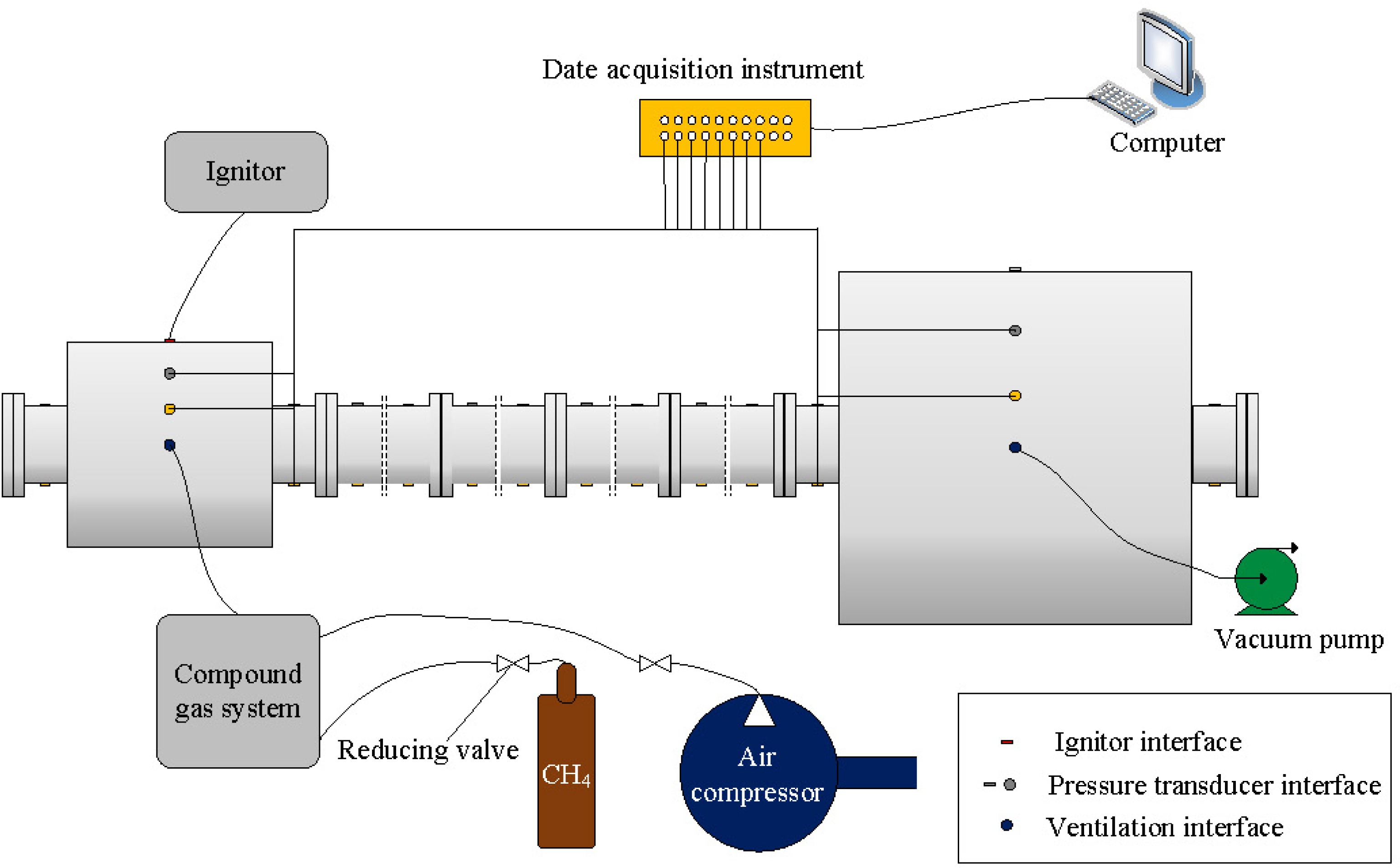
Figure 1.
Schematic of experimental apparatus.
An ignition device is a high-energy electronic ignition device (Model Number: KTD-A) with an ignition energy of 5 J, and the front material of the ignition rod is Kanthal, which is installed on the spherical container. The explosion pressure is obtained by high-frequency pressure transducers (HM90H2-2-V2-F10-W2), the measure range of this transducer is 0~5 MPa, the output voltage is 0~5 VDC, the voltage of power supply is ± 15 VDC, the protection level is IP 67, the frequency resolution is 20 kHz, and the measurement accuracy is ± 0.25% FS, which are installed on the spherical container and pipe. A 2X-8GA vacuum circulating pump is used to replace the waste gas in the interconnected containers with fresh air. The data acquisition device is Sirius produced by DEWE Soft, and the model of the gas distributor is RCS2000-B, which is used to produce the methane-air premixed gas. The methane in the gas distribution system is produced by a methane cylinder, and air is produced by an air compressor.
In the experiment, as shown in Fig. 1, the pressure transducers on the container and the pipe and the data collector to monitor the pressure in advance were installed. The container was vacuumed to −0.1 MPa and confirmed well-sealed. Then the mixed gas from the gas inlet of the primary container through the gas distribution instrument was filled until the internal pressure of the container reaches atmospheric pressure. After staying for a period of time, the high-energy electronic igniter was used to ignite the combustible gas. And the development and intensity of explosion were analyzed by the pressure measured by the data acquisition device. Based on the explosion pressure-time data, the explosion pressure is differentiated against time to obtain the explosion pressure rising rate (dp/dt) value.
Experimental conditions and scheme
-
The experiment was carried out in a sealed container at normal temperature (25 °C) and pressure (0.1 MPa). Ignition position is in the center of the primary container, and the ignition energy is 5 J. Before preparing methane/air mixture, the container was vacuumed to −0.1 MPa and confirmed well-sealed, methane/air mixture (10%) was adopted during the experiment. To achieve reliable results, each experiment was repeated five times at least in this research. According to the measured results, the maximum deviations of the explosion pressure and flame propagation velocity were 5.4% and 7.9% respectively. The specific experimental program is shown in Table 1.
Table 1. Experimental scheme.
Test No. Volume ratio of primary and secondary
containerVolume of primary container (L) Volume of secondary container (L) Length
of pipe
(m)Pipe diameter (m) Test 1 0.1 11 113 2.25 0.059 Test 2 0.2 22 113 2.25 0.059 Test 3 0.4 22 55 2.25 0.059 Test 4 0.5 11 22 2.25 0.020 Test 5 0.5 11 22 2.25 0.059 Test 6 0.5 11 22 2.25 0.108 Test 7 0.5 11 22 2.25 0.133 Test 8 0.5 11 22 4.25 0.059 Test 9 0.5 11 22 6.25 0.059 Test 10 0.5 11 22 8.25 0.059 Test 11 2 22 11 2.25 0.059 Test 12 2.5 55 22 2.25 0.059 Test 13 5.1 113 22 2.25 0.059 Test 14 10.3 113 11 2.25 0.020 Test 15 10.3 113 11 2.25 0.059 Test 16 10.3 113 11 2.25 0.108 Test 17 10.3 113 11 2.25 0.133 Test 18 10.3 113 11 4.25 0.059 Test 19 10.3 113 11 6.25 0.059 Test 20 10.3 113 11 8.25 0.059 -
To analyze the influence of the volume ratio on the methane-air mixture explosion in interconnected containers, an experimental system with different volume ratios (0.1, 0.2, 0.4, 0.5, 2, 2.5, 5.1, and 10.3) is established. Table 2 shows the explosion pressure in the primary and secondary containers under different volume ratio conditions. The explosion pressure rising rate only exists in the explosion pressure rising stage, in the explosion pressure comparison chart, the degree of oscillation is small in the pressure rising stage. And the degree of oscillation is greater only in the pressure drop stage, so the existence of the oscillation range and degree does not affect the acquisition of the maximum explosion pressure rising rate in this research. The maximum explosion pressure rising rate can be obtained through pressure change data and graphs. The maximum explosion pressure and maximum explosion pressure rising rate are shown in Table 2.
Table 2. Explosion test results in primary and secondary containers under different volume ratio conditions.
Volume ratio 0.1 0.2 0.4 0.5 2 2.5 5.1 10.3 *P Primary container Pmax / MPa 0.619 0.625 0.631 0.635 0.610 0.613 0.650 0.677 0.000 Absolute deviation 0.0003 0.0007 0.0000 0.0023 0.0027 0.0010 0.0020 0.0010 − (dP/dt)max / MPa·s−1 17.16 20.37 22.70 24.73 22.31 20.25 17.07 15.10 0.000 KG / MPa·m·s−1 8.70 10.60 9.91 8.40 7.58 8.84 8.89 7.65 − Secondary container Pmax / MPa 0.640 0.644 0.654 0.657 0.825 0.831 0.874 0.908 0.000 Absolute deviation 0.0000 0.0020 0.0023 0.0047 0.0043 0.0010 0.0030 0.0063 − (dP/dt)max / MPa·s−1 20.59 22.72 26.46 28.41 44.98 48.36 53.90 60.03 0.001 KG / MPa·m·s−1 10.43 11.83 11.55 9.65 15.27 21.11 28.06 30.42 − As seen from Figs 2 & 3 and Table 2, there is an obvious size effect on the gas explosion in the interconnected containers. When the volume ratio is less than 1, the maximum explosion pressure and the maximum rate of pressure rise in the primary and secondary containers both increase with increasing volume ratio, and the maximum explosion pressure difference is small. The difference in the maximum explosion pressure between the primary and secondary containers is relatively small, approximately 0.02 MPa. When the volume ratio greater than 1, the maximum explosion pressure in the primary and secondary containers both increase as the volume ratio increases. However, as the volume ratio increases, the maximum pressure rising rate of the primary container gradually decreases, while the pressure rising rate of the secondary container gradually increases. The difference in the maximum explosion pressure between the primary and secondary containers is larger than 0.2 MPa, which is approximately 10 times that of the former. The parameter KG of the primary container in Table 2 changes with the increase of the volume ratio. It reaches the highest value when the volume ratio is 0.2. It indicates that the explosion in the primary container is more dangerous at this time. When the volume ratio is greater than 0.5, the pressure growth index of the secondary container changes greatly with the increase of the volume ratio, the pressure growth index reaches its peak value when the volume ratio is 10.3.
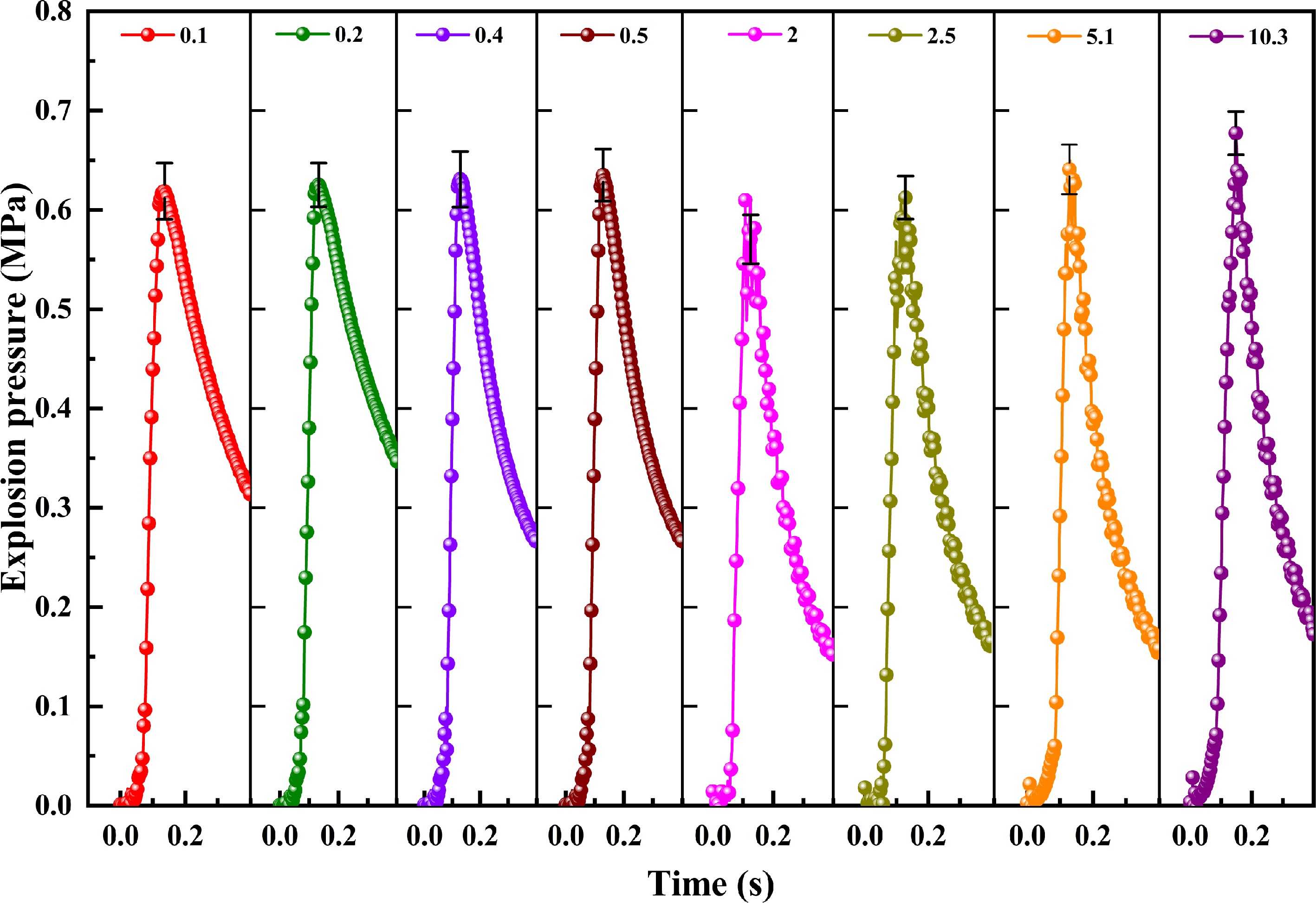
Figure 2.
Explosion pressure curves in the primary container under different volume ratio conditions.
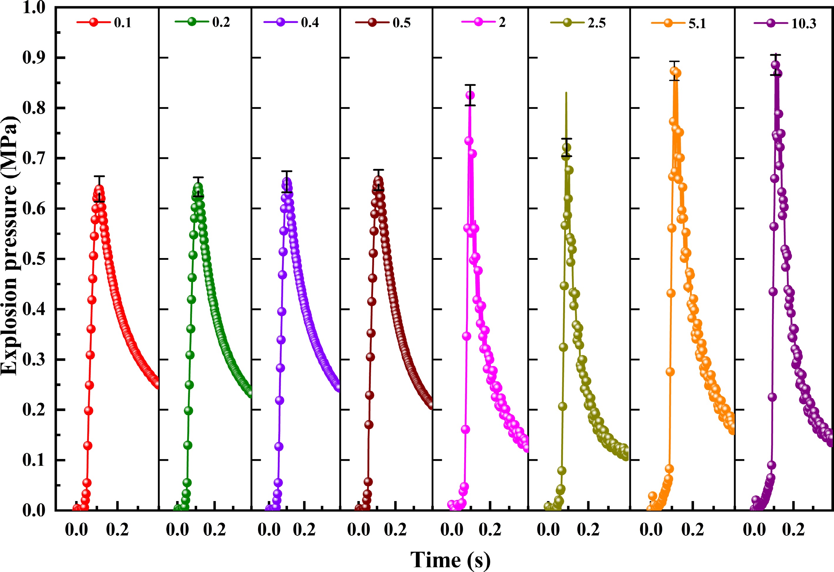
Figure 3.
Explosion pressure curves in the secondary container under different volume ratio conditions.
The maximum explosion pressure of the primary and secondary containers increases with the increase of the volume ratio. When the volume of the secondary container is relatively small, the pressure in the secondary container is increased by the pre-compression effect of the explosion combustion pressure wave of the primary container. After the pressure increases, the flame and air flow return to the primary container, so that the maximum explosion pressure of the primary and secondary containers increases continuously, as the volume ratio increases, the turbulence in the primary and secondary containers increases, and the pressures in both containers also increase[17]. When the volume of the primary container is large enough, the heat loss is sufficient to cause a large drop in pressure. So when the volume ratio is greater than 1, the maximum rate of pressure rise in the primary container decreases with the volume ratio, and that of the secondary container increases with the volume ratio[18].
Before fitting, we performed a T-test on these data to ensure that the data was statistically significant, the results are shown in Table 2. Because there are differences in personnel operation and the degree of gas mixing in each experiment in the connected container, in order to confirm whether the experimental results of different experiments are statistically significant, probability in hypothesis testing (*P) is calculated. The *P value is a probability value obtained statistically based on the significance test method, and reflects the probability of the difference between the samples due to the sampling error. On the basis that *P < 0.05 which indicates the results are statistically significant, it shows that the difference between the maximum explosion pressure and the maximum explosion rise rate obtained by multiple experiments is statistically significant. Since the R2 is greater than 0.9, we consider these predictive models to be effective.
When the volume ratio less than 1, the explosion prediction model in the primary container is:
$ {{p}}_{{max}}\text{ = 0.61262 + 0.0706 × }\lambda { - 0.055}\times{{l}\text{}}^{\text{2}}\text{} \quad {{R}}^{\text{2}}\text{ = 0.9}\text{775}\text{} $ (2) $ (dp/dt)_{max}=14.72+29.25\times \lambda - 19.65\times \lambda^2\quad {{R}}^{\text{2}}\text{=0.9}\text{202} $ (3) The explosion intensity prediction model in the secondary container is:
$ {{p}}_{{max}}\text{ = 0.6340 + 0.054 × }\lambda { - 0.016}\times{{l}\text{}}^{\text{2}}\text{} \quad{{R}}^{\text{2}}\text{ = 0.9}\text{791}\text{} $ (4) $ (dp/dt)_{max} = 18.53 + 21.20\times \lambda - 3.045\times \lambda^2\quad {{R}}^{\text{2}}\text{ = 0.9}\text{990} $ (5) When the volume ratio is greater than 1, the explosion prediction model in the primary container is:
$ {{p}}_{{max}}\text{ = 0.5712 + 0.02013 × }\lambda { - 9.536 }\times{\text{ 10}\text{}}^{{-4}}\text{×}{{l}\text{}}^{\text{2}}\text{} \quad {{R}}^{\text{2}}\text{ = 0.9}\text{892}\text{} $ (6) $ (dp/dt)_{max} = 26.51-2.641\times \lambda + 0.1489\times \lambda^2\quad {{R}}^{\text{2}}\text{ = 0.9411} $ (7) The explosion intensity prediction model in the secondary container is:
$ {{p}}_{{max}}\text{= 0.78 + 0.02392 × }\lambda { - 0.00112}\times{{l}\text{}}^{\text{2}}\text{} \quad {{R}}^{\text{2}}\text{ = 0.9}\text{940}\text{} $ (8) $ (dp/dt)_{max} = 37.66+4.214\times \lambda - 2.770\times \lambda^2 \quad {{R}}^{\text{2}}\text{ = 0.99}\text{41} $ (9) Where Pmax is the maximum explosion pressure, MPa; (dP/dt)max is the maximum explosion pressure rising rate, MPa/s; λ is the volume ratio.
Effect of pipe length
-
As seen from the previous section, when the volume ratio is 0.5 and 10.3, the maximum explosion pressure rising rate and the maximum explosion pressure value reach the peak respectively, and the risk of explosion in the container is greater. In this section, the volume ratio will be fixed and pipes with different lengths (2.25, 4.25, 6.25, and 8.25 m) are used to study the effect of pipe length on the explosion characteristics in the primary and secondary containers.
It can be seen from Figs 4 & 5 that the size effect of the pipe length on methane-air explosion in the primary container and secondary container is obvious. The maximum explosion pressures in both the primary and secondary containers increase with pipe length at a volume ratio of 0.5 or 10.3. The maximum explosion pressure exhibited a larger change when the volume ratio is 10.3. At this point, the maximum explosion pressure in the secondary container increased from 0.908 MPa at a 2 m pipe length to 1.398 MPa at an 8 m pipe length, and the pressure difference reached 0.490 MPa. Thus, under this condition, the influence of the pipe length on the maximum explosion pressure in the secondary container is very clear. When the volume ratio is 0.5, the oscillation in the container is small, which is the opposite of the oscillation intensity at a volume ratio of 10.3.
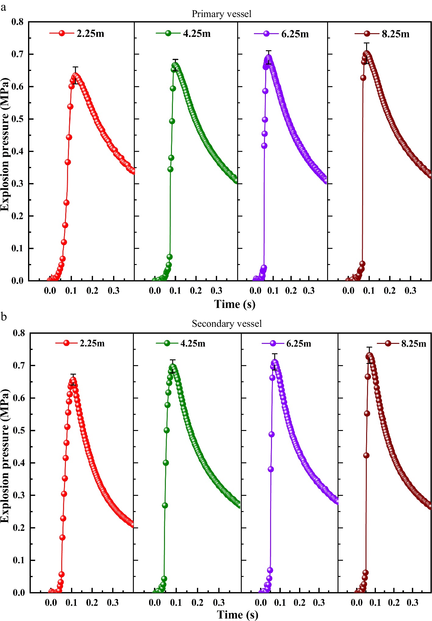
Figure 4.
Explosion pressure curves in the primary and secondary containers with different pipe lengths and a 0.5 volume ratio of the primary and secondary containers.
Figure 5.
Explosion pressure curves in the primary and secondary containers with different pipe lengths and a 10.3 volume ratio of the primary and secondary containers.
In addition, the oscillation intensity increases as the pipe length increased at a volume ratio of 10.3. It can be seen from Table 3 that when the volume ratio is 0.5, the difference in maximum explosion pressure and the maximum rate of pressure rise between the primary and secondary containers is small, which is different to the value at a volume ratio of 10.3. As shown in Tables 3 & 4, these data have statistical significance (*P < 0.05). Based on the experimental results, the required prediction models can be obtained.
Table 3. Explosion test results in primary and secondary containers under different pipe length conditions with a vessel ratio of 0.5.
Volume ratio (0.5) Pipe length 2.25 m 4.25 m 6.25 m 8.25 m *P Primary container Pmax / MPa 0.635 0.667 0.690 0.703 0.000 Absolute deviation 0.0023 0.0007 0.0017 0.0057 − (dP/dt)max / MPa·s−1 24.73 67.66 103.55 143.55 0.048 KG / MPa·m·s−1 8.40 24.00 38.19 54.80 − Secondary container Pmax / MPa 0.657 0.697 0.711 0.734 0.000 Absolute deviation 0.0047 0.0017 0.0043 0.0006 − (dP/dt)max / MPa·s−1 28.41 56.44 81.41 104.14 0.030 KG / MPa·m·s−1 9.65 20.02 30.01 39.72 − Table 4. Explosion test results in primary and secondary containers under different pipe length conditions with a vessel ratio of 10.3.
Volume ratio (10.3) Pipe length 2.25 m 4.25 m 6.25 m 8.25 m *P Primary container Pmax / MPa 0.677 0.726 0.771 0.831 0.000 Absolute deviation 0.0010 0.0050 0.0033 0.0020 − (dP/dt)max / MPa·s−1 15.10 42.30 76.22 102.3 0.046 KG / MPa·m·s−1 7.65 21.73 39.68 53.94 − Secondary container Pmax / MPa 0.908 0.963 1.154 1.398 0.000 Absolute deviation 0.0063 0.0070 0.0050 0.0000 − (dP/dt)max/ MPa·s−1 60.03 90.93 161.47 236.70 0.043 KG / MPa·m·s−1 30.42 46.72 84.08 124.80 − When the volume ratio is 0.5, the explosion prediction model in the primary container is:
$ {{p}}_{{max}}\text{ = 0.5917 + 0.2377 × }{l}{ - 0.00123}\times{{l}}^{\text{2}}\text{} \quad {{R}}^{\text{2}}\text{ = 0.9}\text{997} $ (10) $ (dp/dt)_{max}=-16.87+21.44\times l-0.1828\times l^2\quad {{R}}^{\text{2}}\text{=0.99}\text{76} $ (11) The explosion prediction model in the secondary container is:
$ {{p}}_{{max}}\text{ = 0.6155 + 0.02368 × }{l}{ - 0.00114}\times{{l}}^{\text{2}}\text{} \quad {{R}}^{\text{2}}\text{ = 0.9}\text{406} $ (12) $ (dp/dt)_{max} = -2.068 + 15.92\times l - 0.3314\times l^2\quad {{R}}^{\text{2}}\text{ = 0.99}\text{99} $ (13) When the volume ratio is 10.3, the explosion prediction model in the primary container is:
$ {{p}}_{{max}}\text{ = 0.6397 + 0.01774 × }{l}{ + 7.562}\times{\text{10}\text{}}^{{-4}}\text{ × }{{l}}^{\text{2}}\text{} \quad {{R}}^{\text{2}}\text{ = 0.9}\text{955}\text{} $ (14) $ (dp/dt)_{max} = -16.29 + 15.47\times l - 0.06933\times l^2\quad {{R}}^{\text{2}}\text{ = 0.99}\text{28} $ (15) The explosion prediction model in the secondary container is:
$ {{p}}_{{max}}\text{ = 0.9259 - 0.03464 × }{l}{ + 0.01176}\times{{l}}^{\text{2}}\text{} \quad {{R}}^{\text{2}}\text{ = 0.98}\text{69}\text{} $ (16) $ (dp/dt)_{max} = 42.56 + 2.319\times l + 2.770\times l^2\quad {{R}}^{\text{2}}\text{ = 0.99}\text{02} $ (17) Where Pmax is the maximum explosion pressure, MPa; (dP/dt)max is the maximum explosion pressure rising rate, MPa/s; l is the length of the pipe, m. Since the R2 is greater than 0.9, this model has a certain practical value.
As is shown in Tables 3 & 4, the
Pmax value in the secondary container is larger than that in the primary container. Simultaneously, when the ignited container is constant, a longer pipe leads to a larger Pmax. For the same pipe length, the container of 10.3 volume ratio is more dangerous. For the same volume ratio, the secondary container is more dangerous (compared with the primary container, the P max value of the secondary container is larger). This is because an increase in pipe length causes an obvious accelerated effect of the pipe on the flame and pressure wave, and the explosion flame becomes a jet flame before the secondary container[19]. As the turbulence of the jet flame is large and the temperature is high, after the mixed gas enters the secondary container, it will be ignited, which makes the turbulence degree in the secondary container larger. Compared with the primary container, the explosion pressure in the secondary container is larger at this time, and the maximum rate of pressure rise is also larger[20, 21]. Thus, for the same connecting pipe, the larger the explosion container is, the lower the explosion strength. Effect of pipe diameter
-
It can be seen from the results above that when the volume ratios are 0.5 and 10.3, the device is more dangerous. Therefore, in this section, these two working conditions are selected. The pipe length is fixed (2.25 m), and pipes with different diameters (0.02 m, 0.059 m, 0.108 m, and 0.133 m) are used to study the effect of pipe diameter on the explosion characteristics of the interconnected containers. Figure 6 shows the change in the explosion pressure in the primary and secondary containers with different pipe diameters and a 0.5 volume ratio of the primary and secondary containers. Figure 7 shows the change in the explosion pressure in the primary and secondary containers with different pipe diameters and a 10.3 volume ratio of the primary and secondary containers.
Figure 6.
Explosion pressure curves in the primary and secondary containers with different pipe diameters and a 0.5 volume ratio of the primary and secondary containers.
Figure 7.
Explosion pressure curves in the primary and secondary containers with different pipe diameters and a 10.3 volume ratio of primary and secondary containers.
As seen from Figs 6 & Figs 7, the size effect on gas explosion in the interconnected containers is noticeable. As the diameter of the pipe increases, the explosion pressures in both the primary and secondary containers decrease gradually. In addition, when the volume ratio is 10.3, the oscillation intensities in the primary container and the secondary container are more intense than those at 0.5. The maximum explosion pressure increases from 0.707 MPa to 0.943 MPa, and the difference is 0.236 MPa, which is 10 x that of interconnected containers with a volume ratio of 0.5. From Tables 5 & 6, the maximum explosion pressure rise rates in both the primary and secondary containers decrease with an increase in the pipe diameter when the volume ratios are 0.5 and 10.3. The maximum rate of pressure rise in the secondary container is always greater than that in the primary container, and the difference changes slightly. However, when the mass ratio is 10.3, the maximum rate of pressure rise in the primary container is always smaller than that in the secondary container, and the difference value decreases gradually with the pipe diameter, which is 15 x the volume ratio of 0.5.
Table 5. Explosion test results in primary and secondary containers under different pipe diameter conditions with a vessel ratio of 0.5.
Volume ratio (0.5) Pipe diameter 0.02 m 0.059 m 0.108 m 0.133 m *P Primary container Pmax / MPa 0.680 0.635 0.605 0.588 0.000 Absolute deviation 0.0017 0.0003 0.0043 0.0027 − (dP/dt)max / MPa·s−1 28.85 24.73 19.90 16.93 0.006 KG / MPa·m·s−1 9.32 8.40 7.50 6.78 − Secondary container P max / MPa 0.701 0.657 0.632 0.611 0.000 Absolute deviation 0.0010 0.0020 0.0023 0.0040 − (dP/dt)max / MPa·s−1 32.51 28.41 23.11 19.13 0.005 KG / MPa·m·s−1 10.50 9.65 8.71 7.66 − Table 6. Explosion test results in primary and secondary containers under different pipe diameter conditions with a vessel ratio of 10.3.
Volume ratio (10.3) Pipe diameter 0.02 m 0.059 m 0.108 m 0.133 m *P Primary container Pmax / MPa 0.707 0.677 0.652 0.639 0.000 Absolute deviation 0.0023 0.0037 0.0130 0.0053 − (dP/dt)max / MPa·s−1 17.61 15.10 12.50 10.05 0.009 KG / MPa·m·s−1 8.80 7.65 6.56 5.40 − Secondary container P max / MPa 0.943 0.908 0.873 0.849 0.000 Absolute deviation 0.0020 0.0023 0.0000 0.0007 − (dP/dt)max / MPa·s−1 74.12 60.03 52.88 46.77 0.003 KG / MPa·m·s−1 37.03 30.42 27.76 25.14 − As shown in Tables 5 & 6, the KG value decreases with an increase in the pipe diameter. According to the t-test results, these data are statistically significant (*P < 0.05). Then, we use the same method as above to process the data and got the prediction model we needed.
When the volume ratio is 0.5, the explosion prediction model in the primary container is:
$\begin{split}& p_{max} = 0.7036 - 0.00133\times d/1000 + 3.573\times 10^{-6}\times(d/1000)^2\quad\\& {{R}}^{\text{2}}\text{ = 0.9816}\end{split} $ (18) $\begin{split}& (dp/dt)_{max} = 30.77 - 0.09761\times d/1000 - 4.358\times (d/1000)^2\quad\\& {{R}}^{\text{2}}\text{ = 0.9978}\end{split} $ (19) The explosion prediction model in the secondary container is:
$\begin{split}& p_{max} = 0.7221 - 0.0012\times(d/1000) + 2.937\times 10^{-6}\times(d/1000)^2\quad\\& {{R}}^{\text{2}}\text{ = 0.9517}\end{split} $ (20) $\begin{split}& (dp/dt)_{max} = 34.04 - 0.07578\times(d/1000) - 2.637\times(d/1000)^2\quad\\& {{R}}^{\text{2}}\text{ = 0.9942}\end{split} $ (21) When the volume ratio is 10.3, the explosion prediction model in the primary container is:
$\begin{split}& p_{max} = 0.7226 - 8.481 \times 10^{-4}\times(d/1000) + 1.687\times 10^{-6} \times (d/1000)^2\quad \\&{{R}}^{\text{2}}\text{ = 0.9816} \end{split}$ (22) $\begin{split}& (dp/dt)_{max} = 18.44 - 0.04414\times (d/1000) - 1.318\times(d/1000)^2\quad\\& {{R}}^{\text{2}}\text{ = 0.9947} \end{split}$ (23) The explosion prediction model in the secondary container is:
$\begin{split}& p_{max} = 0.9579 - 8.204\times 10^{-4}\times (d/1000) + 1.018 \times 10^{-7}\times (d/1000)^2\quad \\&{{R}}^{\text{2}}\text{ = 0.9816}\end{split} $ (24) $\begin{split}& (dp/dt)_{max}=81.13-0.3991\times (d/1000)+0.00111\times (d/1000)^2\quad\\& {{R}}^{\text{2}}\text{=0.9760} \end{split}$ (25) Where Pmax is the maximum explosion pressure, MPa; (dP/dt)max is the maximum explosion pressure rising rate, MPa/s; d is the inner diameter of the pipe, m. this model has a certain practical value since the R2 is greater than 0.9.
As illustrated in Tables 5 & 6, in the case of the four different pipe diameter connections, the size effect of pipe diameter on the explosion of methane-air mixed gas in the interconnected containers is clear. The pressure change trends in the primary and secondary containers with different pipe diameters are basically the same. The change in the pipe diameter has a large impact on the flames, and pressure waves, and the gas flow generated in the primary container spreads to the secondary container. The burned and unburned mixed gas flows to the secondary container through the pipe under the action of the high pressure generated in the primary container, and the high pressure in the secondary container will make the mixed gas return to the primary container again, then the mixed gas will continuously flow between the two containers, finally entering a stable state[22]. The smaller the diameter of the pipe is, the greater is the resistance to the mixed gas flows in the pipe, and the turbulence of the airflow also increases. The explosion flame becomes a jet flame before the secondary container, and after it enters the secondary container, the mixed gas will be ignited, which makes the turbulence degree in the secondary container larger. The mixed gas flows in the secondary container is transmitted through the pipe to the primary container, which increases the explosion pressure in the primary container. Increasing the diameter of the pipe weakens the separation role of the two containers, resulting in a decrease in the turbulence degree of the reflected airflow, and the explosion pressure also decreases[23].
-
According to the experimental results, the empirical formulas of methane-air explosion pressure in cylindrical interconnected vessels with different sizes are obtained in this paper, and the influence law and mechanism of different factors on the explosion characteristics in interconnected vessels are analyzed. Besides, some experimental results are founded as follows:
(1) Both the Pmax and KG of the secondary container increase with the increase of the volume ratio. When the volume ratio is greater than 1, the oscillation is obvious either in the primary container or the secondary container. When the volume ratio is less than 1, the pressure difference between the primary container and secondary container is small. When the volume ratio is higher than 1, the Pmax of the primary container will grow rapidly, and the pressure difference between the primary container and the secondary container is obviously increased.
(2) For the same connecting pipe and volume ratio, as the length of the pipe increases, both the Pmax and (dp/dt)max of the primary container and secondary container increase, compared with the primary container, the Pmax in the secondary container is larger at this time, and the (dp/dt)max is also larger.
(3) The pressure change trends in the primary and secondary containers with different pipe diameters are basically the same. Increasing the diameter of the pipe will reduce Pmax and (dp/dt)max, when the volume ratio is 10.3, the larger the diameter of the pipe is, the lower the drop of the (dp/dt)max of the secondary container becomes.
Therefore, reducing the length of the pipes is beneficial to reduce the strength of explosion, increasing pipe diameter can effectively reduce explosion pressure and accident losses. Effective control of the container volume and the length and diameter of the intermediate pipe have a great guiding effect on the intrinsic safety design of the equipment container.
The authors are grateful for National Natural Science Foundation of China under Grant No. 52074159, Key R & D programs (Social Development) in Jiangsu Province under Grant No. BE2020710, Key National Natural Science Foundation of China under Grant No. 51834007, Jiangsu Project Plan for Outstanding Talents Team in Six Research Fields (TD-XNYQC-002), Cultivation Program for The Excellent Doctoral Dissertation of Nanjing Tech University under Grant No. 2021-05, and Postgraduate Research & Practice Innovation Program of Jiangsu Province under Grant No. KYCX21_1199.
-
Zhirong Wang is the Editorial Board members of Journal Emergency Management Science and Technology. He was blinded from reviewing or making decisions on the manuscript. The article was subject to the journal's standard procedures, with peer-review handled independently of these Editorial Board members and their research groups.
- Copyright: © 2022 by the author(s). Published by Maximum Academic Press on behalf of Nanjing Tech University. This article is an open access article distributed under Creative Commons Attribution License (CC BY 4.0), visit https://creativecommons.org/licenses/by/4.0/.
-
About this article
Cite this article
Lin CD, Liu CP, Zhang K, Wang ZR. 2022. Methane-air explosion pressures in cylindrical interconnected containers with different dimensions. Emergency Management Science and Technology 2:17 doi: 10.48130/EMST-2022-0017 

Methane-air explosion pressures in cylindrical interconnected containers with different dimensions
- Received: 28 October 2022
- Accepted: 22 December 2022
- Published online: 30 December 2022
Abstract: The characteristics of methane-air explosion in interconnected containers with different dimensions are studied in this paper, and the prediction models are established. The explosion apparatus consists of two cylindrical containers and a connecting pipe, and three structure parameters are selected as influencing factors for the experiments. The explosion pressure, the maximum rate of pressure rise and pressure growth index under different conditions are compared by changing the volume ratio (V1/V2), the length of the pipe, and the inner diameter of the pipe. During the experiment, the combustion and explosion of gas developed from the main container to the auxiliary container. Under different size effect conditions, the maximum explosion pressure in the secondary container was always higher than the maximum explosion pressure in the primary container. The maximum explosion pressure and the maximum rate of pressure rise in the primary and secondary containers both increase with increasing pipe length. With an increase in the pipe diameter, the maximum explosion pressure and the maximum rate of pressure rise both decrease gradually. When the volume ratio changes, the parameters such as the maximum explosion pressure are also affected by the volume changes of the containers at both ends. Therefore, the explosion parameters in both connected containers do not show a single development trend with the increase of the volume ratio. For practical application, in order to reduce the explosion intensity and protect the device, large-diameter pipes should be used and the volume ratio should be reduced.