


-
Liquid air energy storage technology is a new type of large-scale energy storage technology. A cryogenic pump is a vital device for releasing energy and generating power in a liquid air energy storage system. It is mainly used to transport liquid air to release energy and increase its pressure[1]. In engineering practice, the medium in the cryogenic pump is easily affected by the external environment, and cavitation occurs, which leads to a degradation in the performance of the cryogenic pump. Moreover, the physical properties of the low-temperature medium are affected by thermodynamic effects during the cavitation process, which makes the cavitation of the low-temperature medium more complicated. Therefore, it is necessary to study the cavitation of cryogenic pumps.
In recent years, many scholars have conducted experimental studies on cavitation in low-temperature media. Kim et al.[2,3] used water, liquid hydrogen, and liquid oxygen as the media and installed acceleration sensors on the pump volute of cryogenic pumps to study the instability of the inducer of cryogenic pumps when cavitation occurred. Yoshida et al.[4] took the inducer as the research object, conducted a visual experimental study of cavitation under the thermodynamic effect, and analyzed the cavity length and the fluid temperature distribution in the inducer. Jiang et al.[5] used the Venturi tube as the research object and liquid nitrogen as the medium, used the Schnerr-Sauer cavitation model and the Realizable k-ε turbulence model to simulate the cavitation in the cryogenic pump, and conducted a visualization test. The numerical simulation results are in agreement with the experimental results, and the thermal effect has an inhibitory effect on the cavitation of the low-temperature medium.
Numerous studies have used numerical simulation methods to study the cavitation flow field of cryogenic pumps. Rahbarimanesh et al.[6] used open-source software OpenFOAM to simulate the cavitation of liquefied natural gas (LNG) and pointed out that thermodynamic effects slowed down the condensation of LNG bubbles. Zhu et al.[7] took the two-dimensional hydrofoil model as the research object. They used the Schnerr-Sauer cavitation model combined with the energy equation to simulate the cavitation of low-temperature fluid. By comparison with the experimental results, they verified the feasibility of the Schnerr-Sauer cavitation model to simulate the cavitation of low-temperature fluid. Sun et al.[8] improved the Zwart cavitation model and studied the effect of the empirical coefficient of the cavitation model on the cavity length by considering the influence of thermodynamic effects on the physical parameters of low-temperature media. Shi et al.[9] introduced the Merkle cavitation model into CFX software and studied the cavitation flow characteristics of liquid nitrogen and liquid hydrogen by using a hydrofoil model considering the change of medium temperature with flow field temperature. The results showed that the thermodynamic effect was mainly manifested in the shortening of cavity length, and the thermodynamic effect of liquid hydrogen was more obvious than that of liquid nitrogen. Wang et al.[10] took liquid hydrogen as the flow medium and studied the flow law of water and liquid hydrogen inside the inducer based on the modified Kubota cavitation model and SST k-w turbulence model. The results showed that the modified Kubota cavitation model could simulate cavitation well, considering thermodynamic effects. The thermodynamic effect obviously improves the cavitation flow in the inducer. Chen et al.[11] established an effective numerical method for simulating liquid nitrogen cavitation flow, coupled the existing numerical method of low-temperature cavitation flow with the energy equation to consider the thermodynamic effect, and evaluated the thermodynamic effect on cavitation by defining a scalar temperature drop.
Previous researchers have carried out research on cavitation in low-temperature media. The cavitation caused by the pressure drop in the pump is often mainly considered when the cavitation research of the medium in the pump is carried out. However, the influence of the external temperature is not considered at the same time. The cryogenic pump usually works in a very low-temperature environment. The medium in the cryogenic pump is affected by the external temperature and is easily vaporized. For example, the insulation layer of the cryogenic pump is damaged, and the external heat enters the cryogenic pump through the volute wall, causing the medium in the volute to vaporize. In this paper, the numerical simulation method is used to study the cavitation of cryogenic pumps induced by the coupling of pressure drop in the pump and external temperature. The research results have reference values for the selection of cryogenic pump thermal insulation measures and the improvement of anti-cavitation performance.
-
A cryogenic pump with a specific speed of 130 and a rated flow of 50 m3/h is used in this study. Its main structural parameters are listed in Table 1.
Table 1. Main structural parameters of the cryogenic pump.
Pump inlet diameter Di/
mmPump outlet diameter Do/
mmImpeller diameter
D2/mmNumber of blades
z/pcsBlade outlet width
b2/mmImpeller outlet width
b3/mm76 65 137 6 14 30 The three-dimensional software Pro/E was used to build the geometric model of the cryogenic pump, as shown in Fig. 1. To fully develop the flow of the medium in the cryogenic pump, the inlet and outlet sections were extended. The inner flow channel of the cryogenic pump was meshed by ICEM software, the volute and impeller water body meshed with unstructured tetrahedral mesh, the volute tongue region was locally refined, and the inlet and outlet sections meshed with the hexahedral structure, as shown in Fig. 2. When the number of grids is greater than 1.05 million, the range of pump head variation is less than 0.5%, so it is more appropriate when the number of grids is greater than 1.05 million. In the numerical simulation of this paper, the total number of grids is 1,069,312, and the number of grid elements of the inlet straight pipe section, impeller, volute, and outlet straight pipe section of the cryogenic pump is 148,992, 450,179, 396,851, and 73,290, respectively, and the minimum grid quality is 0.3.
Figure 1.
Geometric model of the cryogenic pump.
Figure 2.
Mesh of the cryogenic pump.
Zwart cavitation model
-
In this paper, the Zwart cavitation model[12] is used in the numerical calculation process. When ρ ≤ ρv, the liquid vaporizes into bubbles
$ {R_{\text{e}}} = {F_{\rm{vap}}}\frac{{3{\alpha _{\rm{nuc}}}{\rho _{\rm v} }(1 - {\alpha _{\rm v}})}}{{{R_{\rm B}}}}\sqrt {\frac{2}{3}\frac{{{p_{\rm v} } - p}}{{{\rho _l}}}} $ (1) When ρ > ρv, bubbles condensed into liquid
$ {R_{\rm c}} = {F_{\rm{cond}}}\frac{{3{\rho _{\rm v} }{\alpha _{\rm v}}}}{{{R_{\rm B} }}}\sqrt {\frac{2}{3}\frac{{p - {p_{\rm v}}}}{{{\rho _l}}}} $ (2) where Re and Rc stand for the mass transport during the emergence and collapse of bubbles, respectively, αnuc for the volume fraction of cavitation cores, ρv and ρl for the density of the vapor and the density of the liquid phase, αv for the vapor volume fraction, RB for the bubble radius, ρv for the saturated vapor pressure of the fluid, ρ for the pressure of the fluid, and Fvap and Fcond for the empirical coefficients of the vaporization and condensation source terms.
For the cavitation of the fluid at room temperature, Fvap = 50, Fcond = 0.01, αnuc = 5 × 10⁻⁴, and the bubble radius RB = 1 × 10⁻⁶ m. For the numerical simulation of cavitation affected by thermodynamic effects, the empirical coefficients Fvap and Fcond have an essential influence on the numerical simulation results. Hosangadi & Ahuja[13] found that the empirical coefficient of simulating low-temperature fluid cavitation was smaller than that of normal-temperature fluid cavitation. Sun et al.[8] and Zhang et al.[14] modified the cavitation coefficient in the process of low-temperature cavitation simulation. The vaporization coefficient Fvap was selected as 5, and the condensation coefficient Fcond was selected as 0.001. In the calculation of liquid hydrogen cavitation, Wang et al.[15] reduced the default Fvap and Fcond by ten times. Sun et al.[16] selected 3 for the vaporization coefficient Fvap and 0.0005 for the condensation coefficient Fcond in the numerical simulation of the cavitation of liquid nitrogen around the hydrofoil. In the simulation of low-temperature cavitation, the empirical coefficient of the cavitation model selected by predecessors is smaller than that of normal temperature cavitation. In the numerical simulation of this paper, to ensure the convergence of the numerical simulation, Fvap = 1, and Fcond = 0.0001.
Thermodynamic effects
-
The Zwart cavitation model assumes that the pressure difference between the liquid and gas phases drives the mass transfer between phases, ignoring the influence of thermodynamic effects in cavitation[17]. The physical parameters of low-temperature fluids are easily affected by temperature. Many studies[18−20] showed that thermodynamic effects significantly impact low-temperature cavitation. Therefore, based on the Zwart cavitation model, the impact of thermodynamic effects was considered in this paper.
The conveying medium in the cryogenic pump was liquid nitrogen. Figure 3 shows the variation of the saturated vapor pressure ρv(T) of liquid nitrogen with temperature T in the temperature range of 64−124 K. Formula (3) shows the relationship obtained by fitting, and it is imported into CFX through CEL language for the solution.
$ {p_{\rm v}}(T) = {\text{0}}{\text{.045}}{T^4} - {\text{4}}{\text{.25}}{T^3} - {\text{98}}{\text{.51}}{T^2} + {\text{19600}}{\text{.69}}T - {\text{482140}}{\text{.51}} $ (3) 
Figure 3.
The relationship between saturated vapor pressure and temperature.
Boundary conditions
-
In this paper, CFX software was used for numerical simulation. Zwart cavitation model and RNG k-ε turbulence model were used for the cavitation model and turbulence model. Because the working temperature of liquid nitrogen is 73 K, the boundary condition at the pump inlet adopted the pressure, the inlet temperature was 73 K, and the Total Energy equation was selected. The boundary condition at the pump outlet adopted the mass flow rate, and the outlet flow rate was 13.759 kg/s. The wall surface was chosen as the non-slip wall surface, in which the front cover plate, rear cover plate, and blade were set as the rotating wall surface, and the rest of the wall surface was set as the static wall surface.
Different interfaces represent different energy transfer modes. In the numerical simulation, the interface was set in the following two ways: The interface between the inlet pipe and impeller and the interface between impeller and volute belong to the dynamic and static interface, so the FrozenRotor model was selected. The interface between the outlet extension and the volute belongs to the static-static interface. The high-order convergence mode was used in the calculation process, and the convergence accuracy was 10−5.
The boundary conditions were basically the same in the numerical simulation of cavitation and non-cavitation. The calculation result of single phase no cavitation was taken as the initial value of cavitation simulation. The liquid phase volume fraction at the inlet was set as 1, and the gas phase volume fraction was set as 0. When the cavitation of liquid nitrogen in the pump was induced by the coupling of the pressure drop and the external temperature, the inlet pressure was set as 0.1, 0.09, 0.08, 0.078, 0.075, and 0.073 MPa, respectively. The temperature of the inner volute wall was set as 113, 118, 123, and 128 K, respectively.
-
The H-NPSH curve under different inner wall temperatures is shown in Fig. 4. Under different inner volute wall temperatures, the head of the cryogenic pump decreases with the decrease of the NPSH. When the head of the cryogenic pump is reduced by 3%, the NPSH is lower than 2.8 m, and the cavitation enters a critical state. With the continuous reduction of the NPSH of the cryogenic pump, the cavitation in the impeller of the cryogenic pump intensifies, and the cavitation blocks the internal flow channel of the cryogenic pump, resulting in a sharp drop in the head of the cryogenic pump. When the inner volute wall temperature increases from 113 to 123 K, the head of the cryogenic pump does not change significantly, This indicates that in this temperature range, the outside temperature does not have a severe impact on the cryogenic pump performance. The reasons for this phenomenon are as follows: With the continuous increase in the temperature of the inner volute wall, the external heat enters the cryogenic pump. The fluid temperature in the area near the inner volute wall is relatively high, and the saturated vapor pressure of liquid nitrogen increases with the temperature, which leads to the pressure in the local area of the volute being lower than the saturated vapor pressure of liquid nitrogen. The liquid nitrogen near the volute area is cavitated, but the vapor volume fraction is small, and it is attached to the inner volute wall and does not block the flow channel in the volute, so the head of the cryogenic pump does not change significantly. When the inner volute wall temperature is 128 K, the cavitation in the volute is intensified, so the pump head drops significantly.
Figure 4.
Variation of head with the NPSH at different wall temperatures.
The variation curve of the efficiency of the cryogenic pump with the NPSH under different inner volute wall temperatures is shown in Fig. 5. As the NPSH decreases, the efficiency of the cryogenic pump decreases continuously. The decrease is most obvious when the NPSH is lower than 2.8 m. When the inner volute wall temperature increases from 113 to 123 K, the efficiency of the cryogenic pump remains relatively high. When the inner wall temperature increases to 128 K, the efficiency of the cryogenic pump drops significantly. This is due to the cavitation of liquid nitrogen in the cryogenic pump under this working condition, which seriously impacts the pump's performance, so the efficiency of the cryogenic pump decreases significantly. When the inner volute wall temperature is 128 K, and the NPSH is 5.793 m, the efficiency of the cryogenic pump does not change much compared with that at other inner wall temperatures. This is because the inlet pressure of the pump is relatively high under this working condition. Although the liquid nitrogen in the volute vaporizes, the cavitation is in the initial stage, which does not seriously affect the performance of the cryogenic pump.
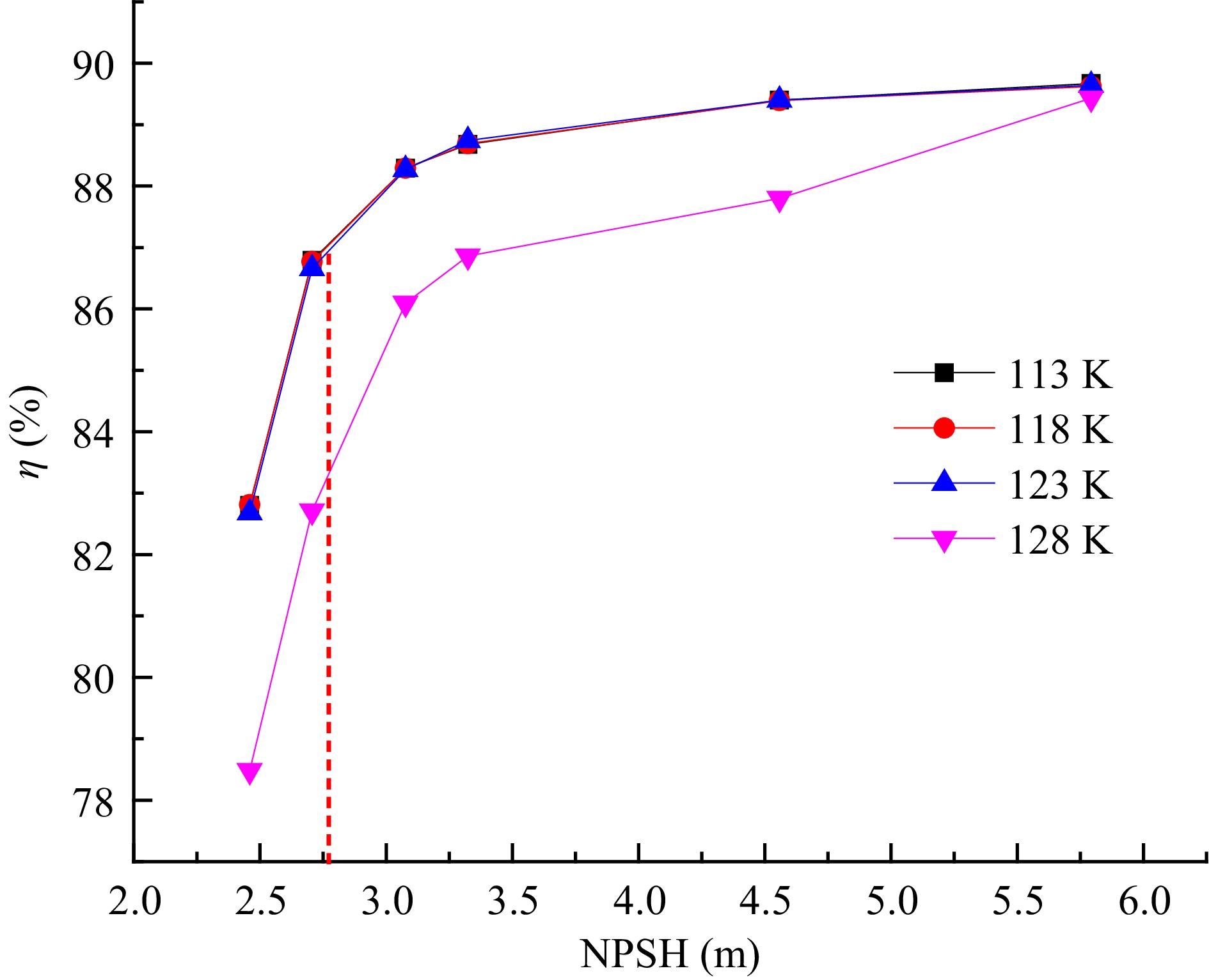
Figure 5.
Variation of efficiency with the NPSH at different inner wall temperatures.
-
When the temperature of the inner volute wall is 113 K, the pressure distribution in the impeller of the cryogenic pump is shown in Fig. 6. The pressure increases gradually in the radial direction, and there is a low-pressure area at the inlet of the impeller of the cryogenic pump. With the continuous development of cavitation, the pressure in the impeller gradually decreases, and the pressure on the suction side of the blade is less than that on the pressure side. Hence, the liquid nitrogen cavitation occurs first at the inlet of the suction side of the blade.
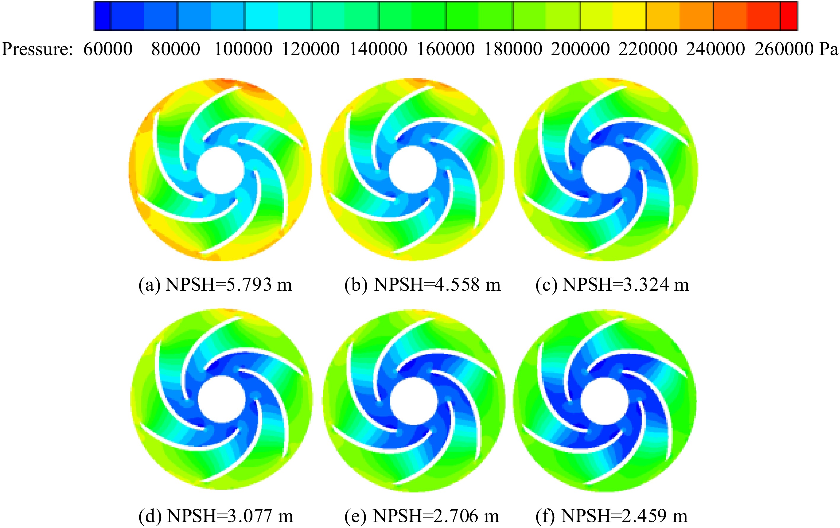
Figure 6.
Distribution of pressure in the impeller.
Vapor distribution in the impeller
-
Figure 7 shows the vapor volume fraction distribution in the impeller of the cryogenic pump when the temperature of the inner volute wall is 113 K. In the initial stage of cavitation, cavitation occurs near the inlet of the suction side of the blade, the vapor volume fraction is small, and the area where cavitation occurs is also small. There is no noticeable squeezing effect on the liquid phase, so there is no apparent impact on the performance of the cryogenic pump. As the inlet pressure continues to decrease, the cavitation inside the impeller enters the critical cavitation stage. The cavitation area of the cryogenic pump continues to expand, the vapor volume fraction gradually increases, and the cavitation occupies the main channel of the impeller, which has an apparent squeezing effect on the liquid phase. This effect leads to the decline of the performance of the cryogenic pump, and the cavitation distribution inside the impeller is asymmetric.
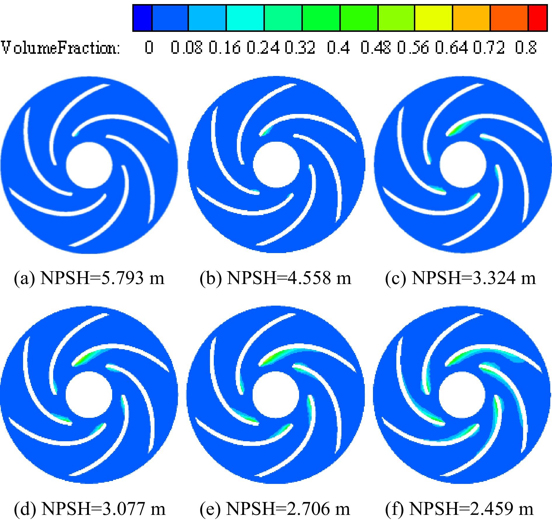
Figure 7.
Distribution of vapor volume fraction in the impeller.
Temperature distribution in the impeller
-
Figure 8 shows the temperature distribution in the impeller of the cryogenic pump when the temperature of the inner volute wall is 113 K. At the inner wall temperature of 113 K, in the initial stage of cavitation, liquid nitrogen absorbs heat when cavitation occurs, so the cavitation occurs on the suction side of the blade, and the temperature in the nearby area is lower. As the inlet pressure continues to decrease, the degree of a cavitation becomes more and more severe. It leads to a gradual increase in the vapor volume fraction, a gradual decrease in the temperature of the cavitation region, and a larger and larger low-temperature area. The temperature distribution and vapor volume fraction distribution in the impeller of the cryogenic pump show a synchronous development trend. Due to the high pressure at the outlet of the impeller, energy is released when the cavitation collapses, so a higher temperature area appears at the outlet of the impeller.
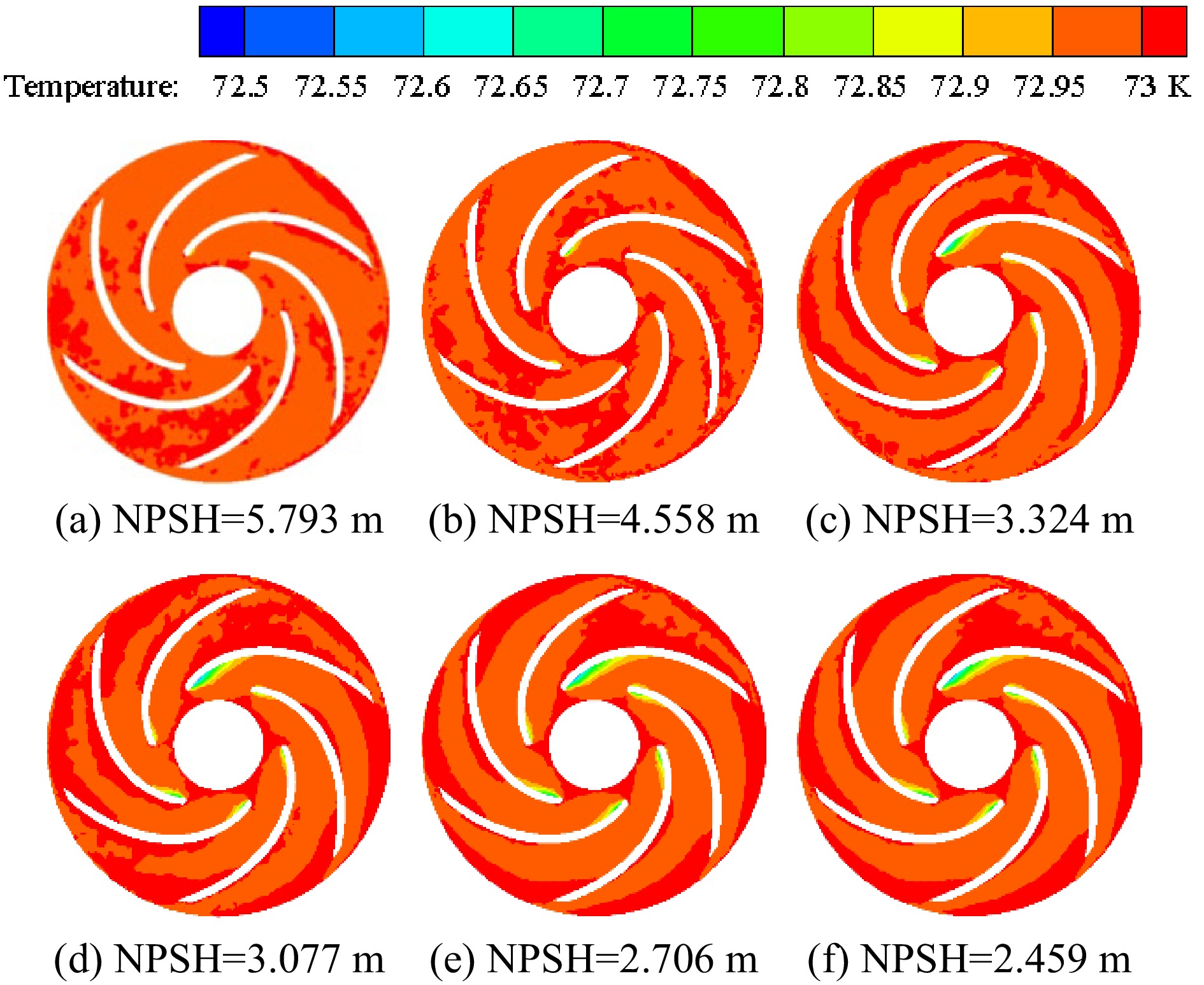
Figure 8.
Distribution of temperature in the impeller.
-
In order to better show the temperature distribution in the volute, the section shown in Fig. 9 (Z = −0.0147 m) was selected for analysis. Figure 10 shows the temperature distribution on the middle section of the volute under different inlet pressures when the temperature of the inner volute wall is 128 K. With the continuous decrease of the inlet pressure, the temperature distribution in the volute does not change significantly, so the influence of the change of the inlet pressure on the temperature distribution in the volute can be negligible. The temperature distribution on the volute section is mainly affected by the temperature of the inner volute wall.
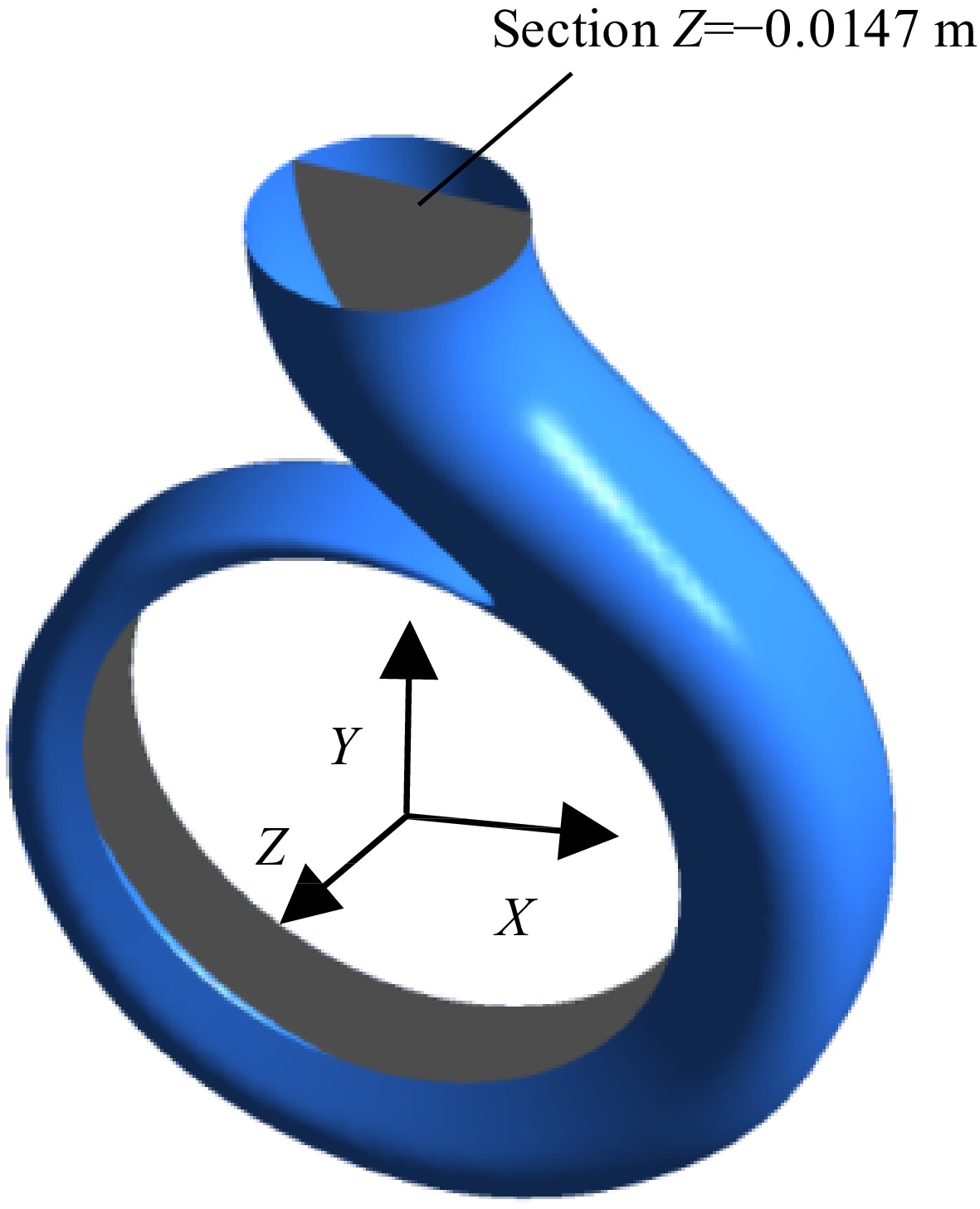
Figure 9.
Section Z = -0.0147 m in the volute.
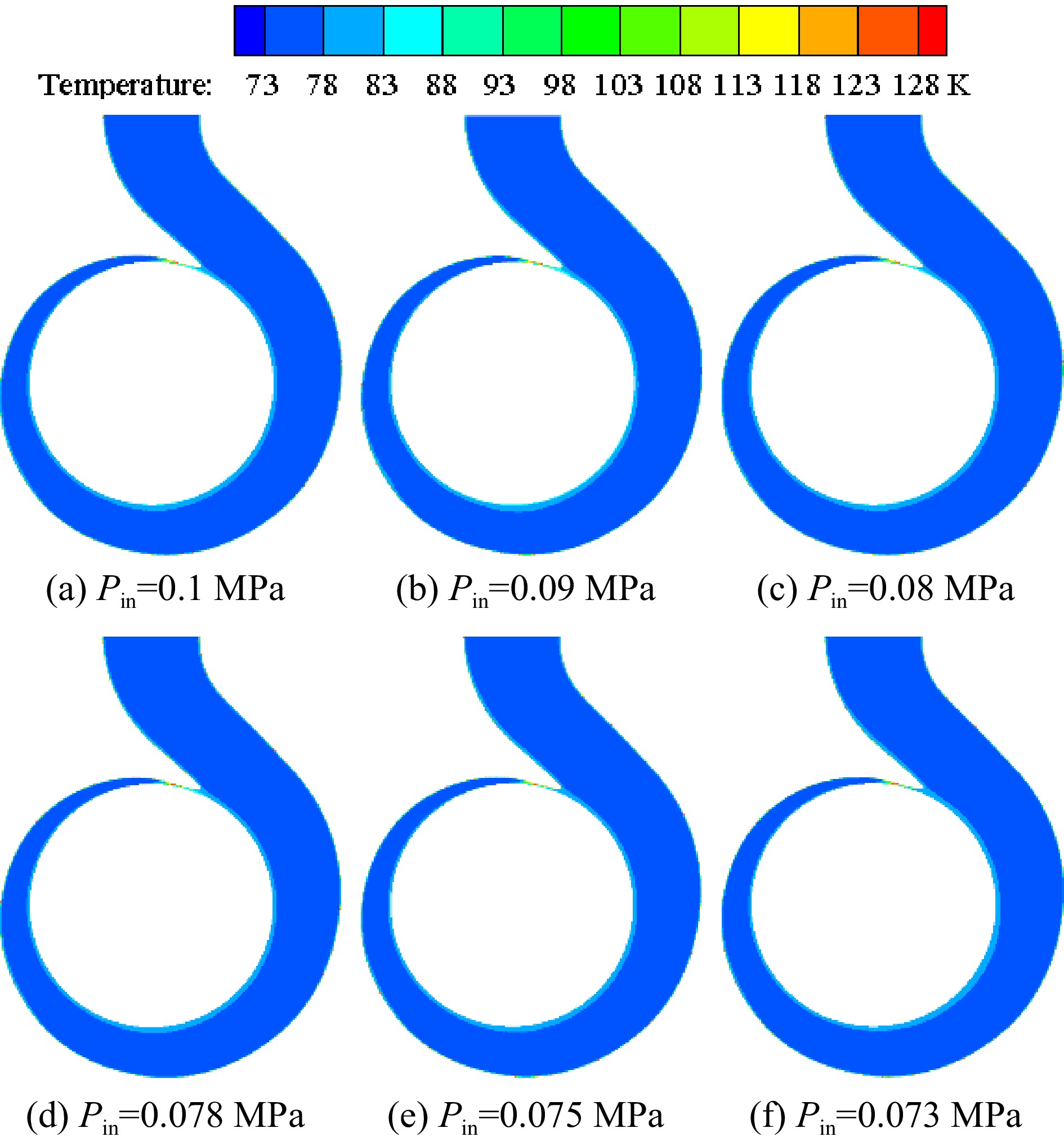
Figure 10.
Distribution of temperature on the volute section under different inlet pressures with the inner wall temperature of 128 K.
Figure 11 shows the temperature distribution on the volute section under different inner wall temperatures of the volute when the inlet pressure is 0.078 MPa. The high-temperature area of the volute section is mainly distributed near the volute tongue and the inner volute wall. As the inner wall temperature gradually increases, the temperature of the high-temperature area gradually increases due to heat transfer. Figure 12 is an enlarged view of the high-temperature area under the condition that the inlet pressure is 0.078 MPa and the temperature of the inner volute wall is 123 K. The thickness of the high-temperature layer near the inner volute wall is relatively thin, and the high-temperature area is distributed in layers. The area near the inner volute wall has a higher temperature. The liquid nitrogen in these areas is prone to vaporization, which has an impact on the performance of the pump. At the base circle of the volute, there is a high-temperature area. The reason for this phenomenon is that on the selected section, this position is relatively close to the inner volute wall, so the area near the base circle has a higher temperature.
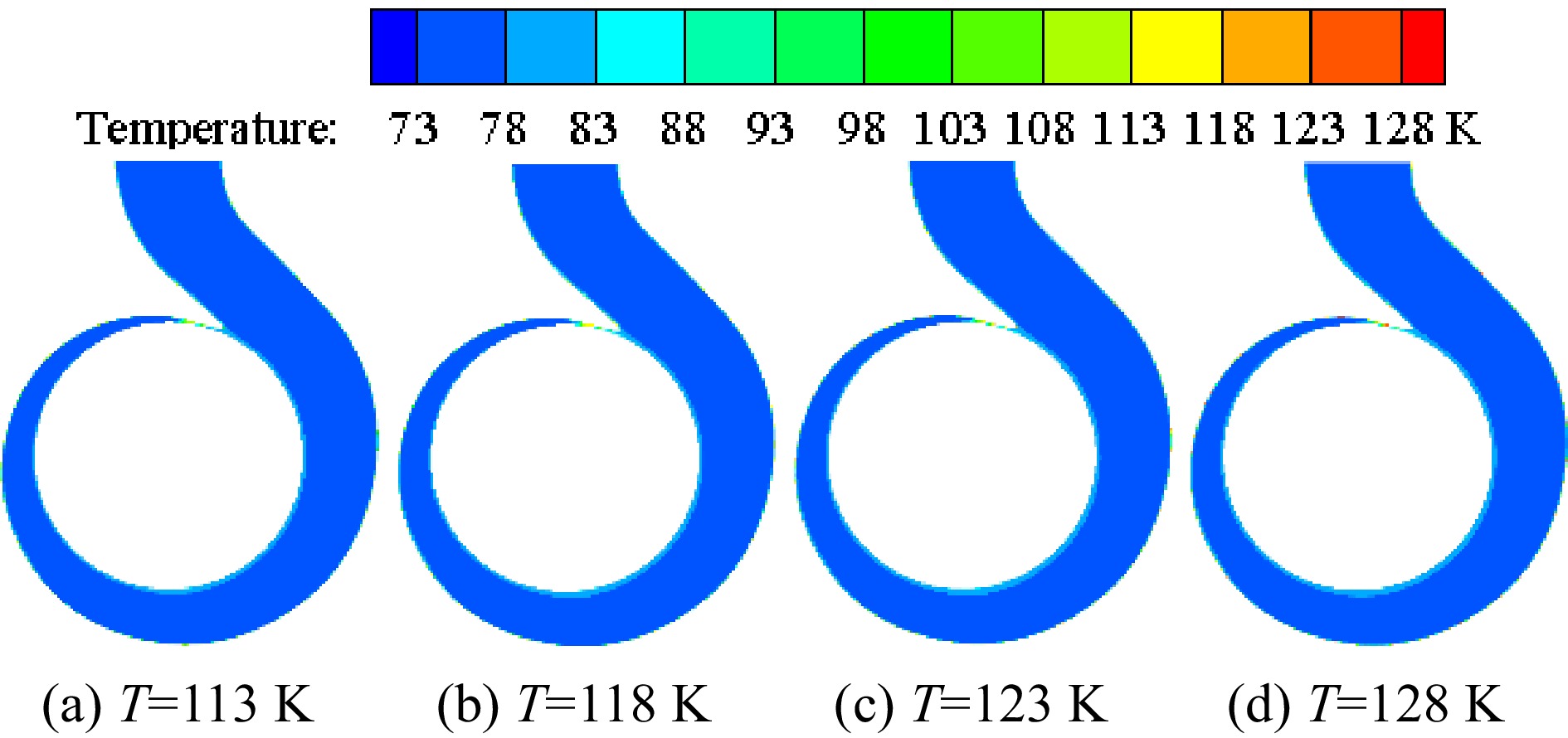
Figure 11.
Distribution of temperature on the volute section under different inner wall temperatures with the inlet pressure of 0.078 MPa.
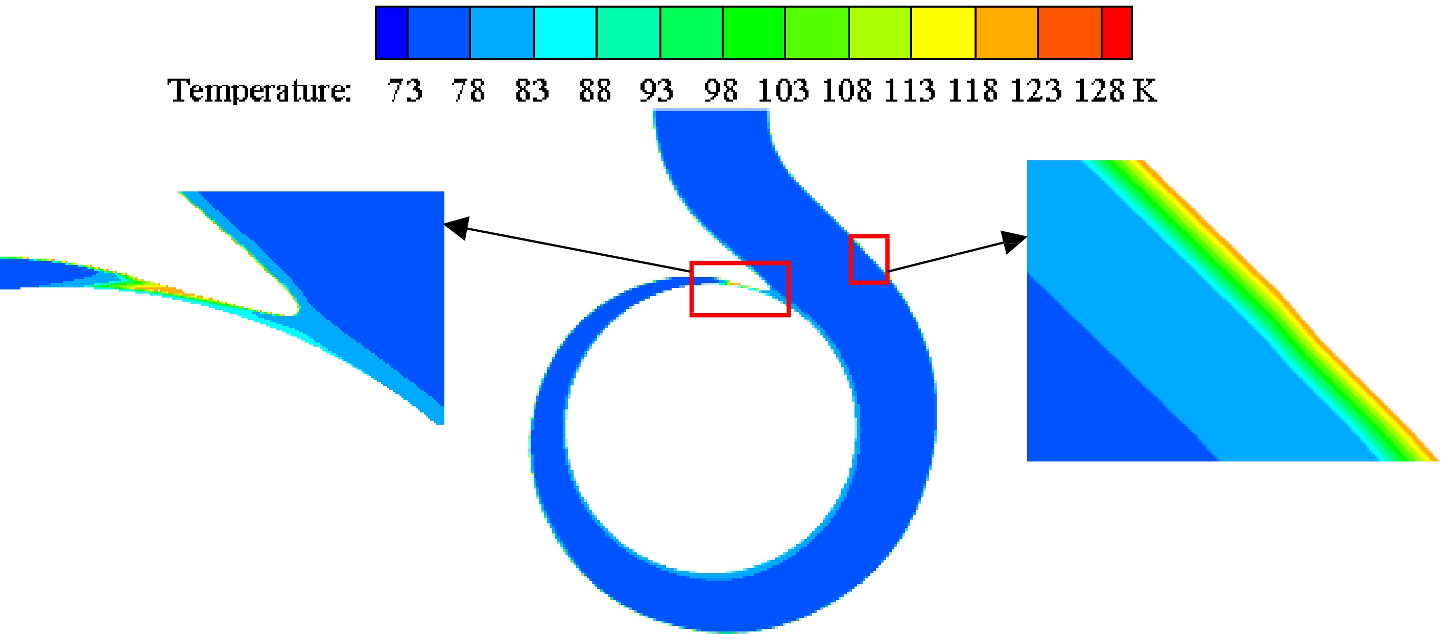
Figure 12.
Enlarged view of high temperature area at the inner wall temperature of 123 K with the inlet pressure of 0.078 MPa.
Pressure distribution in the volute
-
Figure 13 shows the pressure distribution on the middle section of the volute under different inner wall temperatures of the volute when the inlet pressure is 0.078 MPa. When the temperature of the inner volute wall is lower than 123 K, the temperature change of the inner wall has little effect on the pressure distribution in the volute. When the inner wall temperature volute is 128 K, the cavitation in the volute is relatively severe, leading to the flow change in the volute. Therefore, when the temperature of the inner volute wall is 128 K, the pressure distribution of liquid nitrogen in the volute changes significantly.
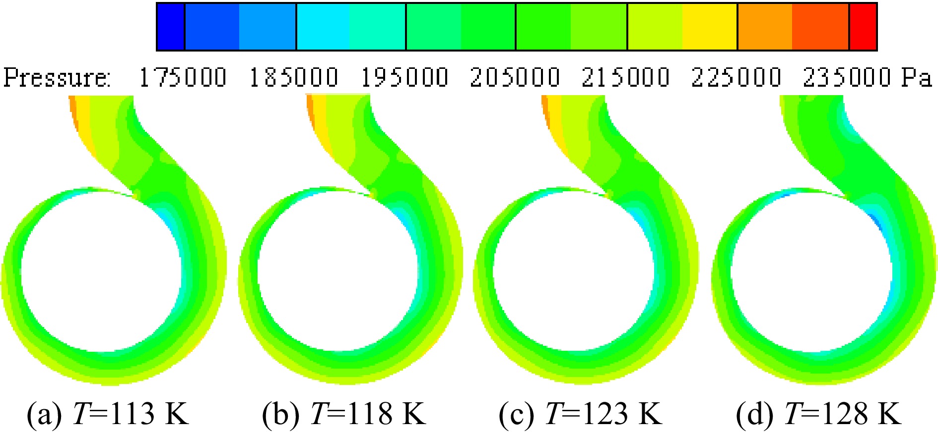
Figure 13.
Distribution of pressure at different inner wall temperatures with the inlet pressure of 0.078 MPa.
Vapor distribution in the volute
-
Figure 14 shows the vapor volume fraction distribution on the middle section of the volute under different inlet pressures when the temperature of the inner volute wall is 128 K. Figure 15 is an enlarged view of the vapor volume fraction in the volute tongue region. The area where cavitation occurs is mainly located near the volute tongue of the cryogenic pump. Due to the higher temperature in the area near the volute tongue, the saturated vapor pressure of the fluid increases with increasing temperature. Liquid nitrogen vaporizes when the pressure in this region falls below the saturated vapor pressure of liquid nitrogen. As the inlet pressure decreases, the pressure in the volute decreases, so the vapor volume fraction in the volute gradually increases as the inlet pressure decreases.
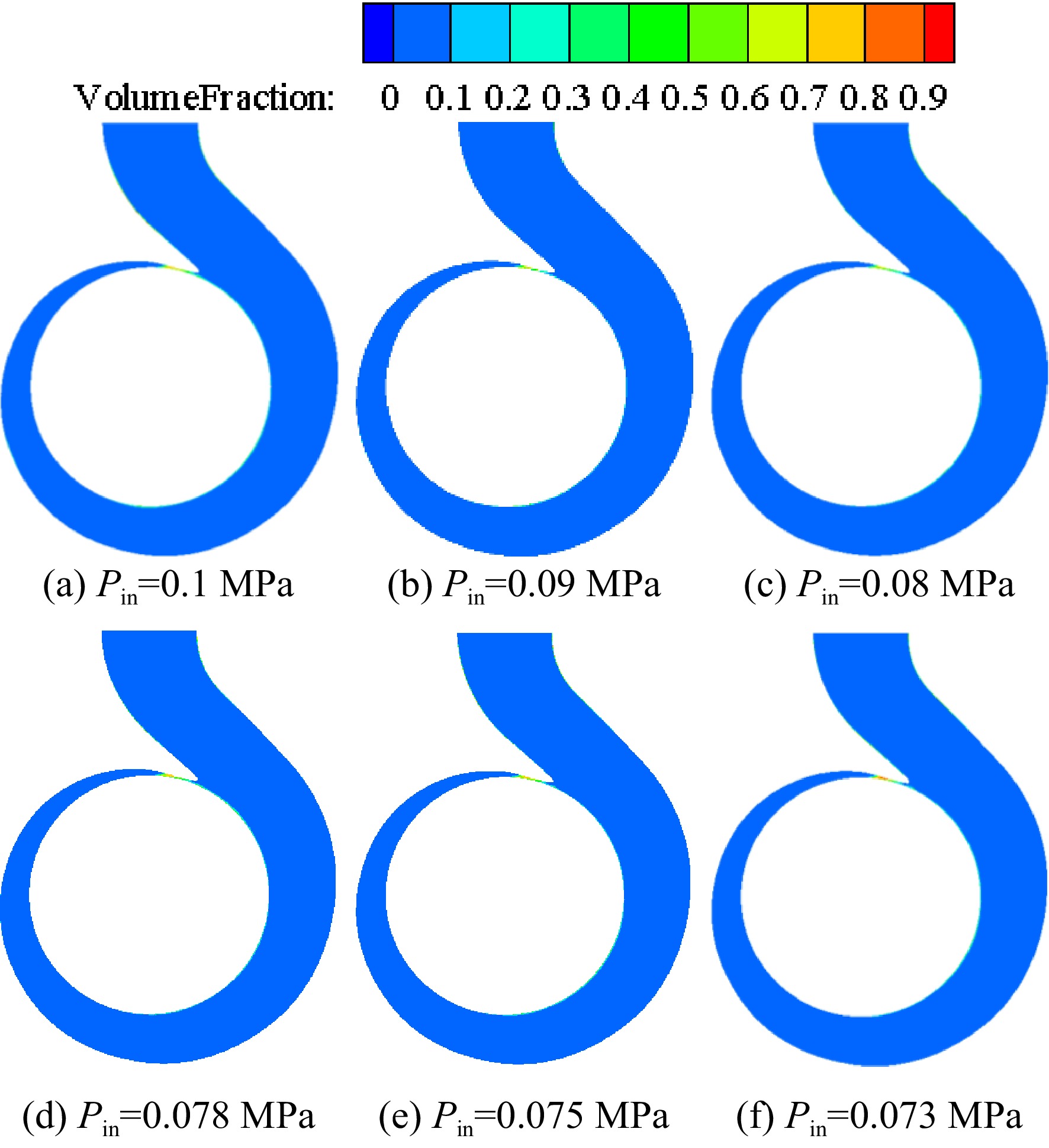
Figure 14.
Distribution of vapor volume fraction on the section of the volute at different pressures with the inner volute wall temperature of 128 K.
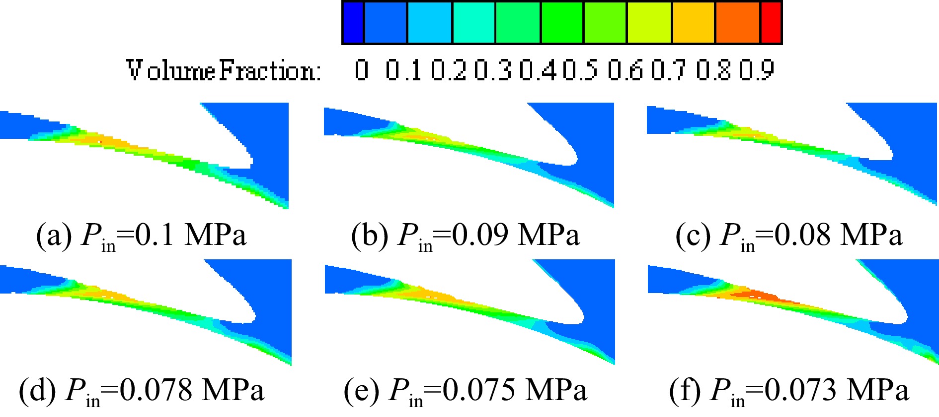
Figure 15.
Enlarged view of vapor volume fraction in the volute area at different inlet pressures with the inner volute wall temperature of 128 K.
Figure 16 shows the vapor volume fraction distribution under different inner volute wall temperatures with the inlet pressure of 0.078 MPa. The liquid nitrogen near the tongue is vaporized due to the high temperature around it. As the temperature on the inner volute wall increases, the temperature in the area around the volute tongue also increases gradually. As a result, the saturated vapor pressure of liquid nitrogen in this area is significantly greater than the local pressure in this area, so the area where cavitation occurs gradually expands, and the vapor volume fraction gradually increases. When the temperature of the inner volute wall is lower than 118 K, no obvious cavitation occurs in the area near the inner volute wall. When the temperature of the inner volute wall is 123 K, cavitation occurs in the area near the inner volute wall. With the continuous increase of the temperature of the inner volute wall, the liquid nitrogen cavitation in the area near the inner volute wall is intensified, and the range of the cavitation area gradually increases. The distribution of the vapor volume fraction is similar to the temperature distribution near the inner volute wall, both of which are layered. The farther away from the inner wall, the lower the vapor volume fraction.
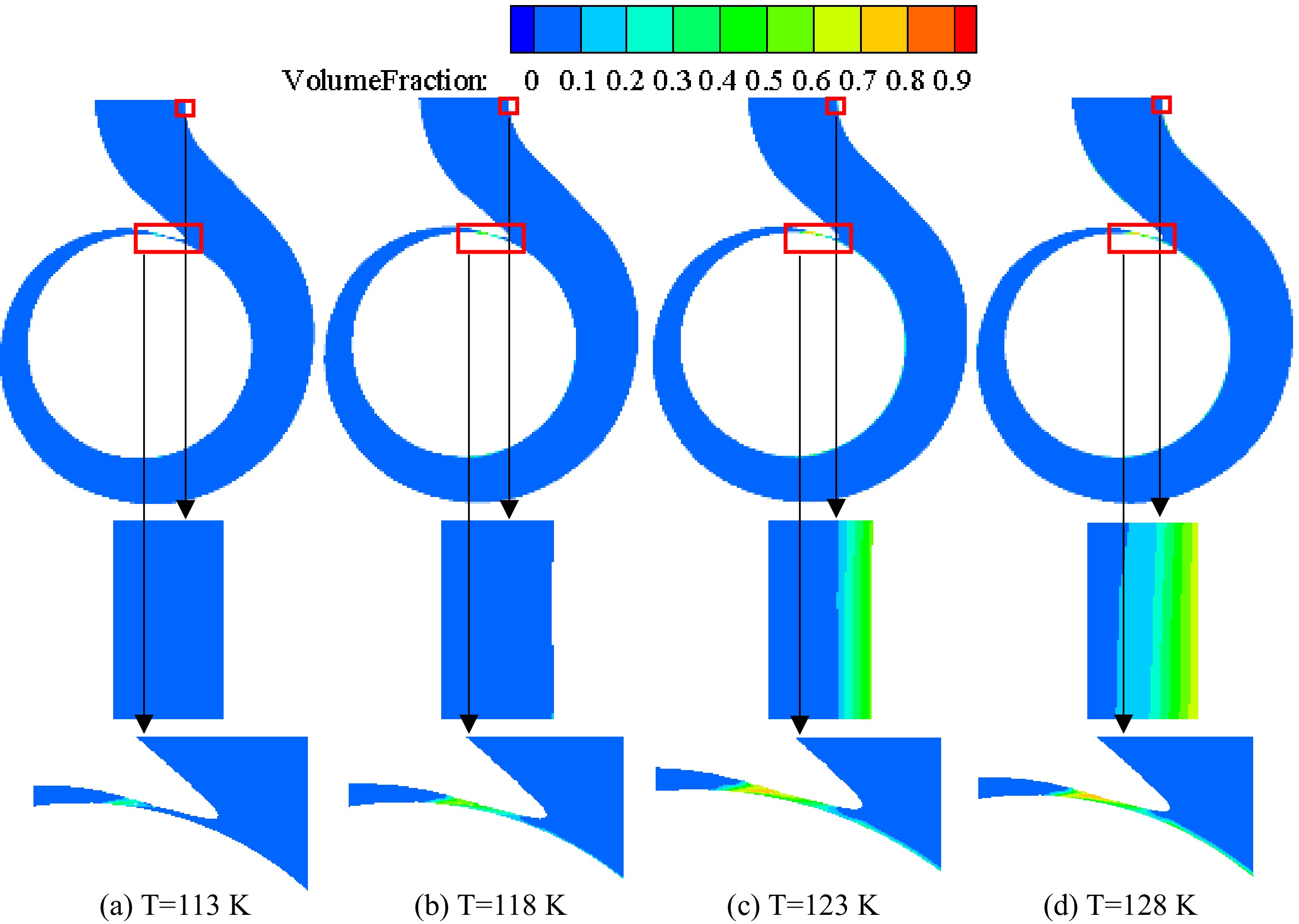
Figure 16.
Distribution of vapor volume fraction at different inner volute wall temperatures with the inlet pressure of 0.078 MPa.
-
In this paper, the numerical simulation method was used to study the cavitation of liquid nitrogen in the cryogenic pump induced by the coupling of pressure drop in pump and external temperature, and the influence of cavitation on the flow in volute and impeller was analyzed. The conclusions are as follows:
(1) The head and efficiency of the cryogenic pump decrease with the decrease of NPSH. When cavitation enters a critical state, the head and efficiency decrease sharply. When the temperature of the inner volute wall is greater than 128 K, the head and efficiency of the cryogenic pump decrease significantly, and the external temperature has a significant impact on the performance of the cryogenic pump.
(2) With the continuous decrease of inlet pressure, the low-pressure area in the impeller gradually expands. With the pump inlet of 0.078 MPa, when the temperature of the inner volute wall is lower than 128 K, the temperature of the inner volute wall has little influence on the pressure distribution in the volute. When the temperature of the inner volute wall is higher than 128 K, the pressure distribution in the volute changes significantly.
(3) Due to the heat absorption of cavitation, the temperature of the cavitation area in the impeller decreases. The influence of inlet pressure on temperature distribution in the volute can be neglected. The high-temperature region in the pump is mainly distributed near the volute tongue and the inner volute wall, and the temperature in this region increases gradually with the increase of the temperature of the inner volute wall.
(4) At a certain temperature, with the continuous decrease of inlet pressure, the cavitation area and vapor volume fraction in the volute and impeller gradually increase. The cavitation region in the volute is distributed near the volute tongue and the inner volute wall, and the vapor volume fraction in this region increases with the increase of the inner wall temperature.
The work was supported by the Natural Science Foundation of Jiangsu Province of China (Grant No. BK20191361), and Postgraduate Research & Practice Innovation Program of Jiangsu Province (Grant No. SJCX21_0493)
-
The authors declare that they have no conflict of interest.
- Copyright: © 2023 by the author(s). Published by Maximum Academic Press on behalf of Nanjing Tech University. This article is an open access article distributed under Creative Commons Attribution License (CC BY 4.0), visit https://creativecommons.org/licenses/by/4.0/.
-
About this article
Cite this article
Yang F, Shao C. 2022. Study on cavitation of liquid nitrogen in pumps induced by coupling of pressure drop and external temperature. Emergency Management Science and Technology 2:18 doi: 10.48130/EMST-2022-0018 

Study on cavitation of liquid nitrogen in pumps induced by coupling of pressure drop and external temperature
- Received: 13 November 2022
- Accepted: 23 December 2022
- Published online: 30 December 2022
Abstract: A cryogenic pump is a kind of pump for transporting low-temperature fluid. The medium in the cryogenic pump is prone to cavitation. To study the cavitation of liquid nitrogen in the pump induced by the coupling of pressure drop and external heating, the Zwart cavitation model and SST k-ω turbulence model were used, and the functional relationship between saturated steam pressure and the temperature was imported into CFX software by CEL language for solution. The external characteristics and internal flow of the cryogenic pump at different inner wall temperatures of volute were analyzed. The results show that when the temperature of the inner volute wall is above 128 K at the inlet pressure of 0.078 MPa, the pressure distribution in the volute changes significantly, the head and efficiency of the cryogenic pump decrease significantly, and the external temperature has a significant impact on the performance of the cryogenic pump. When the temperature of the inner volute wall is lower than 128 K, the temperature of the inner volute wall has little effect on the pressure distribution in the volute. Due to the heat absorption of cavitation, the temperature of the cavitation area in the impeller decreases. The influence of inlet pressure on the temperature distribution in the volute can be ignored. Affected by the external temperature, the high-temperature area in the pump is mainly distributed near the volute tongue and the inner volute wall, and the cavitation area in the volute is also distributed near the same position. The vapor volume fraction in this area increases with the inner wall temperature. The research results have reference values for selecting thermal insulation measures and improving cavitation resistance.
-
Key words:
- Cryogenic pump /
- Pressure drop /
- External temperature /
- Cavitation /
- Numerical simulation