-
The rapid development of electrification is driving wireless power transfer (WPT) technology as a research field with great potential. This type of electrical energy transmission method does not require physical contact and thus is characterized by flexibility and safety. Compared with the traditional wired method, wireless power transfer is gradually demonstrating its advantages in the fields of electric power systems, transportation, aerospace, underwater exploration, home office, and medical devices[1−10]. Efficiency and cost are key considerations when designing and optimizing magnetically coupled wireless energy transmission systems. In practice, the receiving coil will inevitably sustain horizontal misalignment, which will affect the mutual inductance between the coils, thus affecting the transmission efficiency, and the calculation of mutual inductance between the coils is the basis for exploring the change rule of mutual inductance with horizontal misalignment. Therefore, it is of significance to study the mutual inductance calculation method between the transmitting and receiving coil.
Currently, researchers usually use finite element method (FEM) simulation software to obtain the mutual inductance value, but this method has the disadvantages of large computation and is time-consuming. Especially in the case of complex coil distribution or a large number of turns, the simulation may take several hours. On the other hand, considerable progress has been made in the analytical calculation of coil mutual inductance. The utilization of elliptic integrals for calculating the mutual inductance of circular coils in air, whether coaxial or non-coaxial, was proposed by researchers, offering a combination of swiftness and precision[11,12]. Conway expressed the mutual inductance of non-coaxial circular coils in air in the form of Bessel integrals[13]. Hurley et al. extended the mutual inductance formula for single-turn coils to derive an expression for the mutual inductance of coaxial coils in air, which is easily solved by numerical integration[14]. Liu et al. derived the mutual inductance formula for a circular coil at any position based on the Euler angle based on the Neumann integral[15]. However, none of the above-studied models considered the case of magnetic media.
The addition of magnetic media at the coil edges has a significant effect on enhancing the mutual inductance between the coils. For the calculation of mutual inductance with magnetic media, Hurley & Duffy derived analytical expressions for the coaxial mutual inductance of a circular coil with infinite thickness and finite thickness of magnetic media with the help of magnetic vector potential[16], however, the magnetic media is unbounded in the plane. Luo & Wei derived analytical expressions for the mutual inductance of a circular coil coaxial and horizontal misalignment with an unbounded magnetic medium based on the Fourier-Bessel transform[17]. Zhang et al. obtained analytical formulas for the mutual inductance between circular coils at any position of an unbounded double-layer magnetic medium based on the coordinate transformation method[18]. All the above derivations are based on the premise that the magnetic medium material has an infinite plane and a good approximation can only be obtained if the radius of the magnetic medium is twice as large as the coil, which has many obstacles in practical applications.
To solve the mutual inductance calculation problem of circular coils with bounded magnetic media, the researchers utilized the regional eigenfunctions and introduced the truncation domain to express the mutual inductance of circular coils with bounded magnetic media in the form of level summation[19,20]. But the magnetic media is only for unilateral cases, which is incompatible with practical application. Chen et al. established an analytical mapping from geometrical parameters to inductance parameters for finite large magnetic conductors based on the principles of magnetic circuit magnetic reluctance[21] but only in the case when the coil is coaxial is considered, the analytical solution of mutual inductance at the misalignment of the receiving side is not given, and no consideration has been given to material savings. The performance of the cut-hole type and the flat plate type structure, and the ring type and the disc-type structure were compared in terms of coupling and the results proved to be useful for saving magnetic materials[22,23]. In summary, the problem of mutual inductance calculation, when the horizontal misalignment occurs on the receiving side of a bounded magnetic medium with bilateral sides, has not been solved yet, and it is achievable that bilateral magnetic dielectric materials can be reduced in consumption.
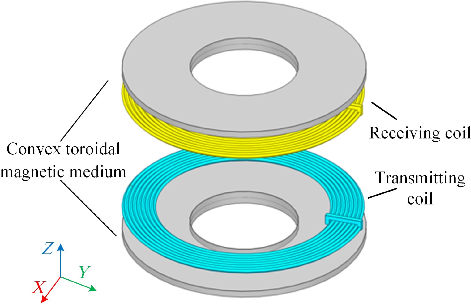
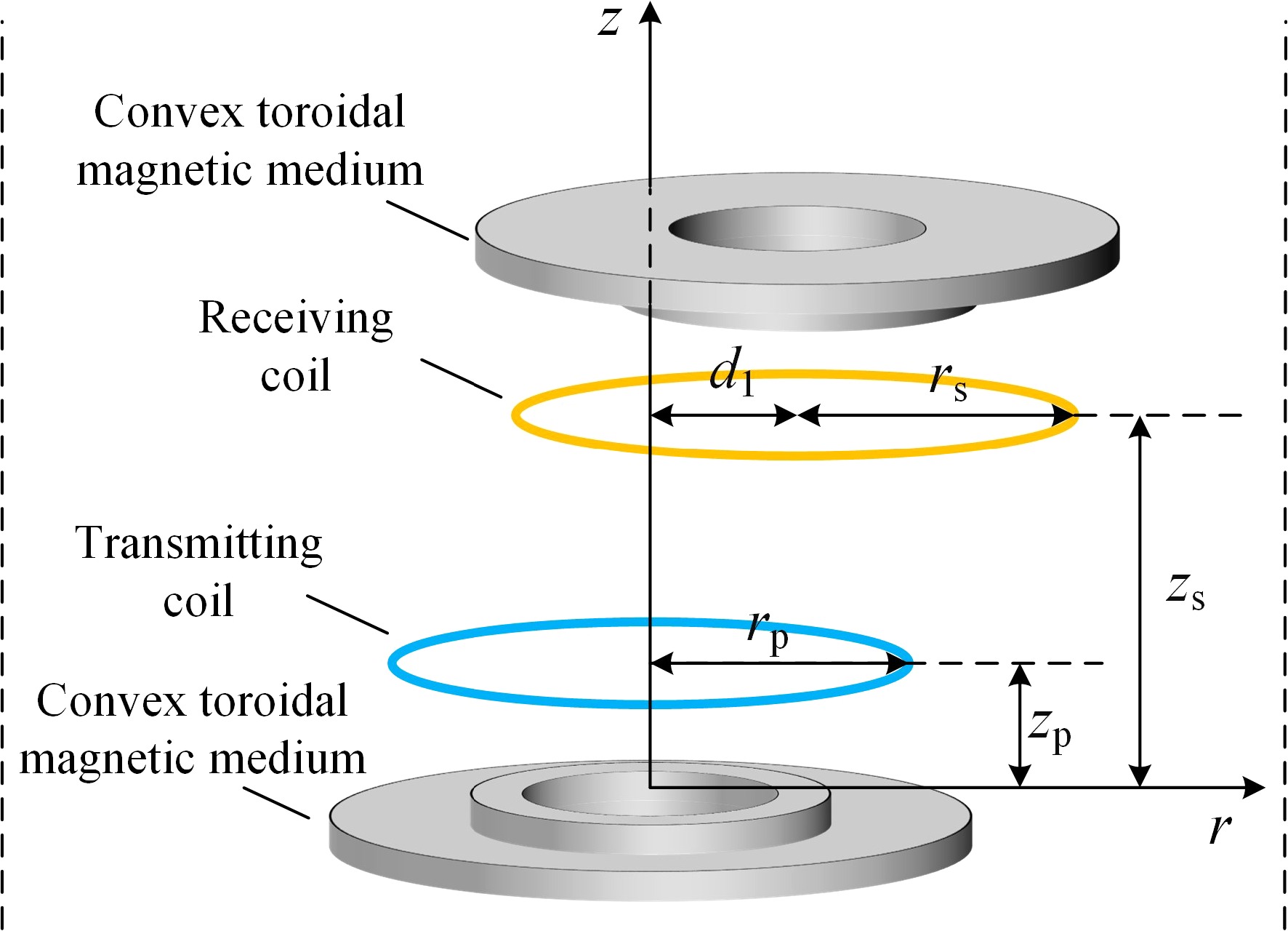
This paper presents a circular coil model with bilateral bounded convex magnetic material rings, as illustrated in Fig. 1. By employing the method of magnetic vector potential position equivalence, the issue of mutual inductance calculation is addressed when the receiver side is coaxial and when there is horizontal misalignment. Firstly, this method divides the model into regions and, based on Maxwell's equations and boundary conditions compute the magnetic vector potentials in each region, deriving analytical expressions for mutual inductance when the receiver side is coaxial. Secondly, utilizing the method of position equivalence, the magnetic material after horizontal displacement is equivalent to the average effect of two coaxial magnetic materials with different radii, so that analytical expressions for mutual inductance are derived for horizontal misalignment. Finally, the calculated values of mutual inductance are compared with finite element simulation values and experimental values.
-
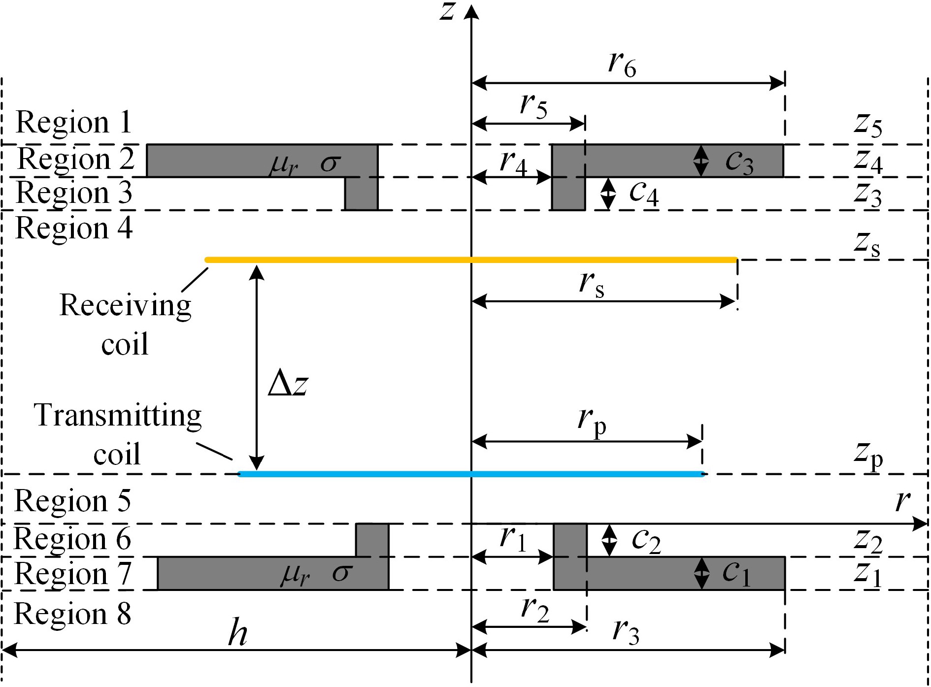
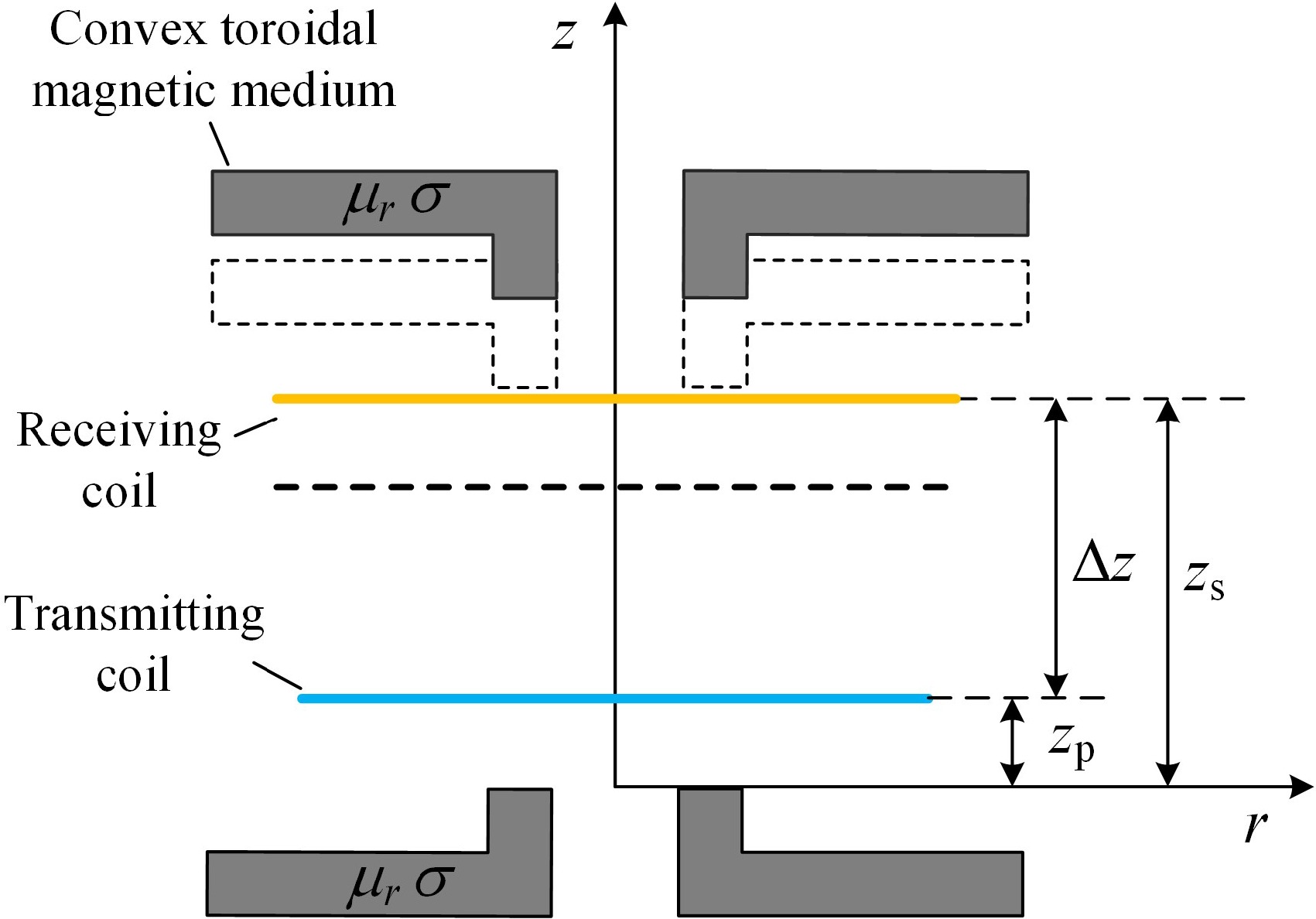
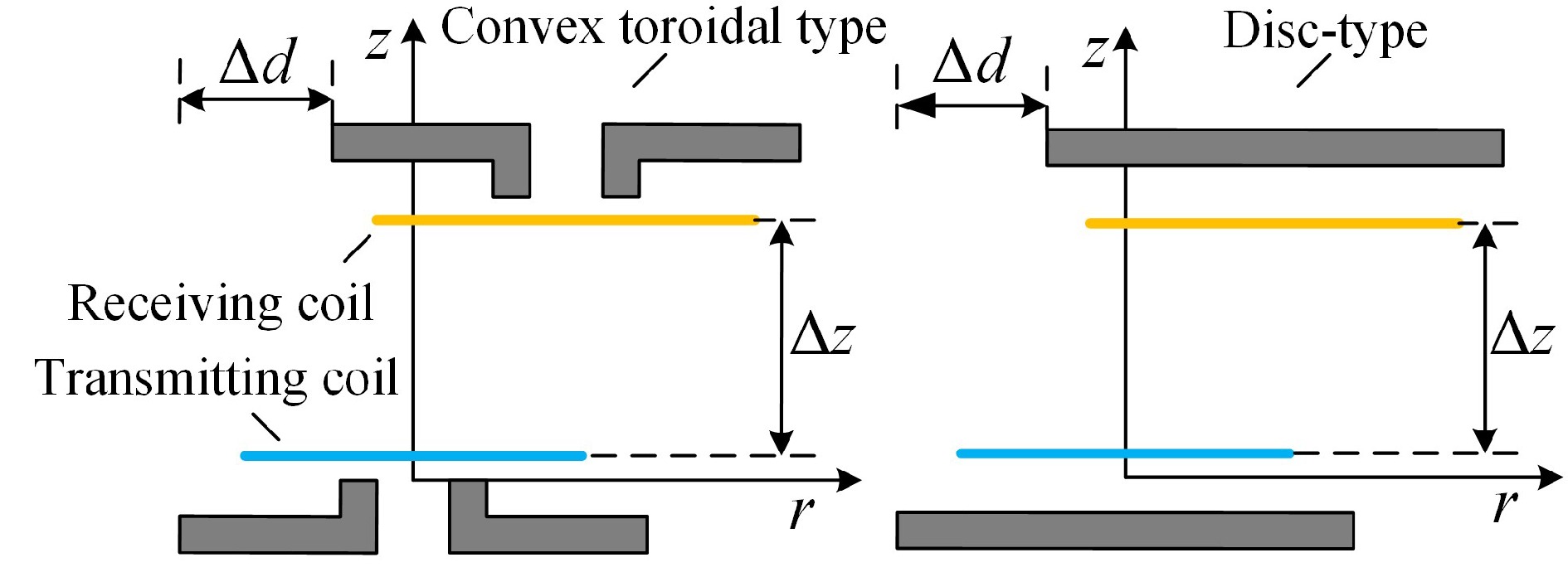
To achieve a similar effect to the enhanced mutual inductance of disc-type magnetic media and to save the use of magnetic media consumables, a single-turn circular coil model with a double-sided bounded convex toroidal magnetic media is constructed by adding a raised portion of the inner edge to the inner ring of the toroidal magnetic media material and a cross-section of the model is shown in Fig. 2.
A cylindrical coordinate system (r, φ, z) is established with the center of the upper surface of the magnetic medium on the emission side as the origin. The symbol μr represents the relative magnetic permeability of the magnetic materials, and σ denotes the conductivity, both of which are linear, homogeneous, and isotropic. Taking the magnetic medium on the transmitting side as an example, r1, and r3 are the inner and outer diameters of the annular part, and its thickness is c1, and the outer diameter of the raised part along the inner edge is r2, and its thickness is c2. The radius of the transmitting coil is rp, and the height at which it is situated is zp. The radius of the receiving coil is rs, and the height at which it is situated is zs. The rest of the medium is air, the permeability of which is set to be the vacuum permeability μ0, and h is the truncated region radius in the model. region radius. Along the z-axis increasing direction, the model is divided into eight regions according to the planes z = z1, z = z2, z = 0, z = zp, z = z3, z = z4, z = z5 as shown in Fig. 2.
Magnetic vector position generalizations by region
-
In electromagnetism, Maxwell's equations relating the magnetic induction B and the magnetic field strength H are:
$ \left\{ {\begin{array}{*{20}{l}} {\nabla \times \boldsymbol{H} = \boldsymbol{J} + \dfrac{{\partial \boldsymbol{D}}}{{\partial t}}} \\ {\nabla \cdot \boldsymbol{B} = 0} \end{array}} \right. $ (1) where, J is the conduction current density and D is the electric displacement vector. Conventional WPT systems usually operate at an operating frequency of 79−90 kHz, a frequency range in which the system can be considered as an ideal magnetically quasi-static system, and therefore the displacement current can be neglected. Introducing the magnetic vector potential A, from the Coulomb norm, Eqn (1) is reduced to the Poisson equation:
$ {\nabla ^2}\boldsymbol{A} = - \mu \boldsymbol{J}$ (2) where, μ is the magnetic permeability of the material. The excitation current flowing through the transmitting coil in the model has an amplitude of I and an angular frequency of ω. The direction of the current is along the φ direction, inducing a magnetic vector potential A in the same direction, i.e., A = Aφ, and from Eqn (2), A satisfies:
$ \dfrac{{{\partial ^2}A}}{{{\partial ^2}r}} + \dfrac{1}{r}\dfrac{{\partial A}}{{\partial r}} + \dfrac{{{\partial ^2}A}}{{{\partial ^2}z}} - \dfrac{A}{{{r^2}}} - j\omega \mu \sigma A = - \mu I\delta \left( {r - {r_{\rm p}}} \right)\delta \left( {z - {z_{\rm p}}} \right) $ (3) where, δ is the impulse excitation function. The magnetic vector potential expression is solved in the column coordinate system in separated variables as:
$ A\left( {r,z} \right) = \sum\limits_{i = 1}^\infty {\left[ {{A_{\rm{mn}}}{J_1}\left( {{\alpha _i}r} \right) + {B_{\rm{mn}}}{Y_1}\left( {{\alpha _i}r} \right)} \right]} \left( {{C_{\rm m}}{{\rm e}^{{\beta _i}z}} + {D_{\rm m}}{{\rm e}^{ - {\beta _i}z}}} \right) $ (4) in the above expression, the subscript i is from 1 to ∞, αi, βi are the eigenvalues, and αi = (βi2+jωμσ)1/2, J1(αir), Y1(αir) represent the first-order Bessel function and the first-order Neumann function, respectively. Amn, Bmn, Cm, and Dm are the regionally unknown coefficients associated with the eigenvalues. They can be obtained from the continuity of the magnetic induction B in the normal direction in the neighboring medium and the continuity of the magnetic field strength H in the tangential direction. The subscript m denotes the location of the region and n denotes the location of the sublayer in the region.
The expression for the magnetic vector potential in each region is determined by the distribution of sublayers inside the region. Regions 1, 4, 5, and 8 all have air sublayers inside, and the Neumann function diverges at Y1(αir) at r = 0. However, the magnetic vector potential is finite here, so the Y1(αir) term is discarded, and therefore the magnetic vector potentials for regions 1, 4, 5, and 8 are derived as:
$ {A_1}\left( {r,z} \right) = \sum\limits_{i = 1}^\infty {{J_1}\left( {{k_i}r} \right)} {D_1}{{\rm e}^{ - {k_i}z}} $ (5) $ {A_4}\left( {r,z} \right) = \sum\limits_{i = 1}^\infty {{J_1}\left( {{k_i}r} \right)} \left( {{C_4}{{\rm e}^{{k_i}z}} + {D_4}{{\rm e}^{ - {k_i}z}}} \right) $ (6) $ {A_5}\left( {r,z} \right) = \sum\limits_{i = 1}^\infty {{J_1}\left( {{k_i}r} \right)} \left( {{C_5}{{\rm e}^{{k_i}z}} + {D_5}{{\rm e}^{ - {k_i}z}}} \right) $ (7) $ {A_8}\left( {r,z} \right) = \sum\limits_{i = 1}^\infty {{J_1}\left( {{k_i}r} \right)} {C_8}{{\rm e}^{{k_i}z}} $ (8) where, ki is the eigenvalue of the aforementioned region. By utilizing the disappearance of the magnetic vector potential at the truncation radius r = h, i.e., J1(kih) = 0, the eigenvalue ki can be determined.
Regions 2, 3, 6, and 7 contain two types of media: air media and magnetic media. Take Region 2 as an example:
(1) In the range of 0 ≤ r < r4 is the air sublayer, and its magnetic vector potential A2air1 is represented as:
$ {A_2}^{air1}\left( {r,z} \right) = \sum\limits_{i = 1}^\infty {{J_1}\left( {{p_{1i}}r} \right)\left( {{C_2}{{\rm e}^{{p_{1i}}z}} + {D_2}{{\rm e}^{ - {p_{1i}}z}}} \right)} $ (9) (2) In the range of r4 ≤ r < r6 is the magnetic medium sublayer, and its magnetic vector potential A2fer2 is represented as:
$ {A_2}^{fer2}\left( {r,z} \right) = \sum\limits_{i = 1}^\infty {\left[ {{A_{22}}{J_1}\left( {{q_{1i}}r} \right) + {B_{22}}{Y_1}\left( {{q_{1i}}r} \right)} \right]} \left( {{C_2}{{\rm e}^{{p_{1i}}z}} + {D_2}{{\rm e}^{ - {p_{1i}}z}}} \right) $ (10) (3) In the range of r6 ≤ r < h is also the air sublayer, and its magnetic vector potential A2air3 is expressed as:
$ {A_2}^{air3}\left( {r,z} \right) = \sum\limits_{i = 1}^\infty {\left[ {{A_{23}}{J_1}\left( {{p_{1i}}r} \right) + {B_{23}}{Y_1}\left( {{p_{1i}}r} \right)} \right]} \left( {{C_2}{{\rm e}^{{p_{1i}}z}} + {D_2}{{\rm e}^{ - {p_{1i}}z}}} \right) $ (11) where, p1i, q1i are the eigenvalues of Region 2 and satisfy the relation q1i = (p1i2+jωμσ)1/2, A2air3 converges to 0 at r = h, and the eigenvalue p1i can be found by Eqn (12).
$ {A_{23}}{J_1}\left( {{p_{1i}}h} \right) + {B_{23}}{Y_1}\left( {{p_{1i}}h} \right) = 0 $ (12) The magnetic vector potential generalization for this region consists of a combination of A2air1, A2fer2, and A2air3. Similarly, the magnetic vector potential expressions for regions 3, 6, and 7 are combinations of the magnetic vector potentials of the sublayers within each region and can be derived similarly.
Boundary conditions
-
In the cylindrical coordinate system, the relationship between the magnetic induction B, the magnetic field strength H, and the magnetic vector potential A can be described as:
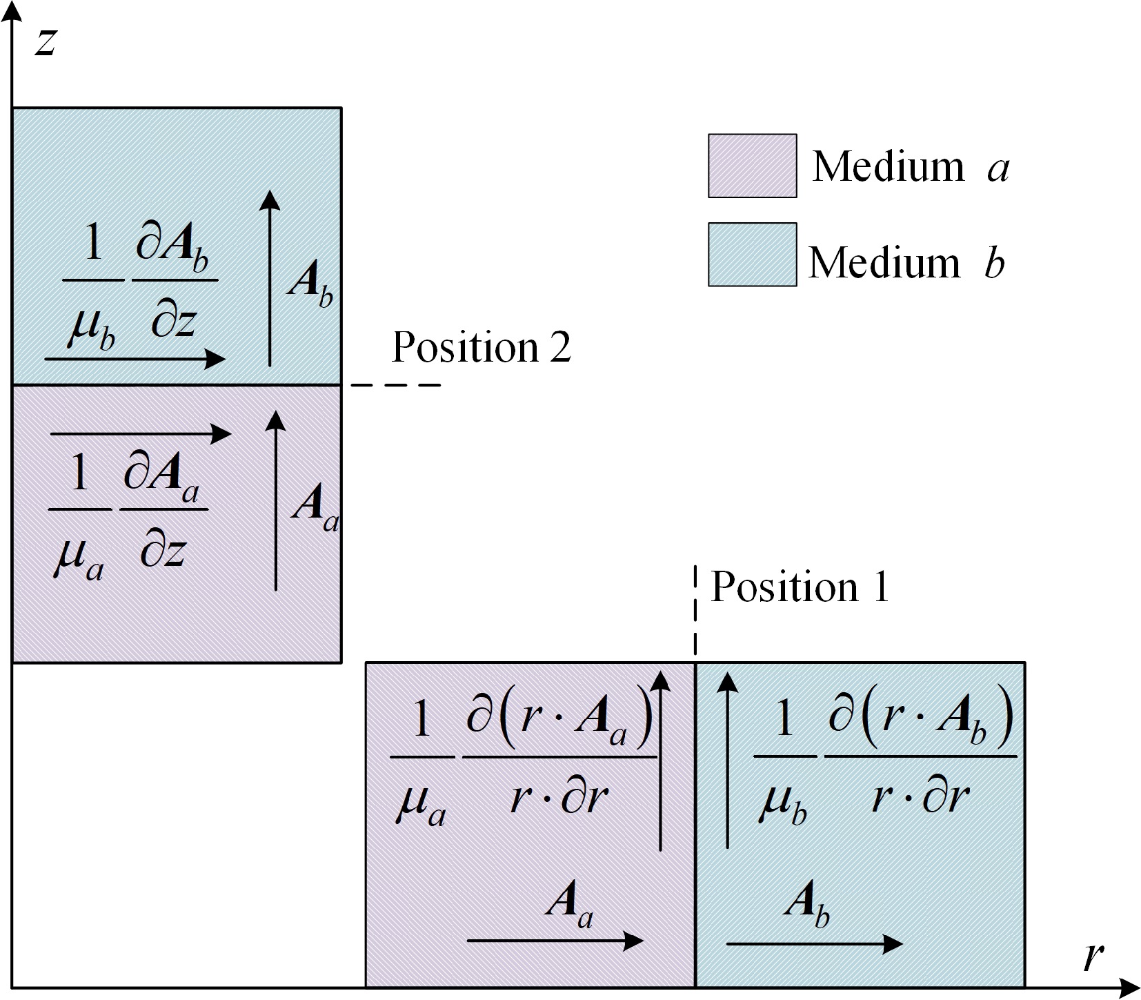
$ \left\{ \begin{gathered} {B_z} = \mu {{ H}_{z}}{\text{ = }}\dfrac{1}{r}\dfrac{{\partial \left( {r \cdot A} \right)}}{{\partial r}} \\ {B_r} = \mu {{ H}_r} = - \dfrac{{\partial A}}{{\partial z}} \\ \end{gathered} \right. $ (13) Therefore, it is necessary to consider the relationship between the magnetic vector potentials at the two positions, as shown in Fig. 3, where the derivatives of the magnetic vector potentials at the dielectric demarcation surface must satisfy the continuity condition along the demarcation interface to ensure the continuity of the electromagnetic field.
In the Fig. 3, Aa and Ab are the magnetic vector potentials in medium a and medium b. μa and μb are the magnetic permeability of medium a and medium b.
At the boundary interface between the air layer and the magnetic medium layer in Region 2, located at r = r1, the continuity of field quantities yields:
$ {J_1}\left( {{q_{1i}}{r_1}} \right) = \left[ {{A_{22}}{J_1}\left( {{q_{1i}}{r_1}} \right) + {B_{22}}{Y_1}\left( {{q_{1i}}{r_1}} \right)} \right] $ (14) $ {\mu _r}{p_{1i}}{J_0}\left( {{p_{1i}}{r_1}} \right) = {q_{1i}}\left[ {{A_{22}}{J_0}\left( {{q_{1i}}{r_1}} \right) + {B_{22}}{Y_0}\left( {{q_{1i}}{r_1}} \right)} \right] $ (15) The association can be solved for the area coefficients A22 and B22 as:
$ {A_{22}} = \dfrac{{{\mu _r}{p_{1i}}{J_0}\left( {{p_{1i}}{r_1}} \right){Y_1}\left( {{q_{1i}}{r_1}} \right) - {q_{1i}}{J_1}\left( {{p_{1i}}{r_1}} \right){Y_0}\left( {{q_{1i}}{r_1}} \right)}}{{{q_{1i}}{J_0}\left( {{q_{1i}}{r_1}} \right){Y_1}\left( {{q_i}{r_1}} \right) - {q_{1i}}{J_1}\left( {{q_{1i}}{r_1}} \right){Y_0}\left( {{q_{1i}}{r_1}} \right)}} $ (16) $ {B_{22}} = \dfrac{{{q_{1i}}{J_0}\left( {{q_{1i}}{r_1}} \right){J_1}\left( {{p_{1i}}{r_1}} \right) - {\mu _r}{p_{1i}}{J_0}\left( {{p_{1i}}{r_1}} \right){J_1}\left( {{q_{1i}}{r_1}} \right)}}{{{q_{1i}}{J_0}\left( {{q_{1i}}{r_1}} \right){Y_1}\left( {{q_{1i}}{r_1}} \right) - {q_{1i}}{J_1}\left( {{q_{1i}}{r_1}} \right){Y_0}\left( {{q_{1i}}{r_1}} \right)}} $ (17) The coefficients A23 and B23 can be found in the same way, and the corresponding coefficients for Regions 3, 6, and 7 are obtained in the same way.
Coaxial mutual inductance expressions
-
To calculate the magnetic flux of the receiving coil, an expression for the magnetic vector potential of the region where the receiving coil is located is required. Associating the magnetic vector potentials from Region 1 to Region 8 and utilizing the boundary conditions at the interfaces z = z1, z = z2, z = 0, z = zp, z = z3, z = z4, z = z5, there are:
$ \dfrac{{\partial {A_i}\left( {r,z} \right)}}{{\partial {z}}} = \dfrac{{\partial {A_{i + 1}}\left( {r,z} \right)}}{{\partial {z}}} $ (18) $ \dfrac{{\partial {A_i}\left( {r,z} \right)}}{{\partial {z}}}\left| {_{z = {z_n}}} \right. - \dfrac{{\partial {A_{i + 1}}\left( {r,z} \right)}}{{\partial {z}}}\left| {_{z = {z_n}}} \right. = - {u_0}J $ (19) The magnetic vector A contains the Bessel function and with the help of the orthogonality of the Bessel function, multiplying the Region 1 magnetic vector A1 by J1(kir)·r and integrating from 0 to h yields:
$ \int_0^h {\sum\limits_{i = 1}^\infty {{D_1}{{\rm e}^{ - {k_i}z}}{J_1}\left( {{k_i}r} \right)} {J_1}\left( {{k_i}r} \right)r{\rm d}r} = \sum\limits_{i = 1}^\infty {\dfrac{{{h^2}}}{2}{D_1}{{\rm e}^{ - {k_i}z}}} {J_2}\left( {{k_i}h} \right) $ (20) Doing the same for both sides of Eqns (18) & (19) and noting the eigenvalues of Regions 3, 6, and 7 as p2i, p3i, and p4i, the equation reduces to:
$ {{\rm e}^{ - {k_i}{z_5}}}{D_1}{E_{10}} = \left( {{{\rm e}^{{p_{1i}}{z_5}}}{C_2} + {{\rm e}^{ - {p_{1i}}{z_5}}}{D_2}} \right){E_{20}} $ (21) $ - {k_i}{{\rm e}^{ - {k_i}{z_5}}}{D_1}{E_{10}} = {p_{1i}}\left( {{{\rm e}^{{p_{1i}}{z_5}}}{C_2} - {{\rm e}^{ - {p_{1i}}{z_5}}}{D_2}} \right){E_{21}} $ (22) $ \left( {{{\rm e}^{{p_{1i}}{z_4}}}{C_2} + {{\rm e}^{ - {p_{1i}}{z_4}}}{D_2}} \right){E_{20}} = \left( {{{\rm e}^{{p_{1i}}{z_4}}}{C_3} + {{\rm e}^{ - {p_{1i}}{z_4}}}{D_3}} \right){E_{30}} $ (23) $ {p_{1i}}\left( {{{\rm e}^{{p_{1i}}{z_4}}}{C_2} - {{\rm e}^{ - {p_{1i}}{z_4}}}{D_2}} \right){E_{21}} = {p_{2i}}\left( {{{\rm e}^{{p_{2i}}{z_4}}}{C_3} - {{\rm e}^{ - {p_{2i}}{z_4}}}{D_3}} \right){E_{31}} $ (24) $ \left( {{{\rm e}^{{p_{2i}}{z_3}}}{C_3} + {{\rm e}^{ - {p_{2i}}{z_3}}}{D_3}} \right){E_{30}} = \left( {{{\rm e}^{{k_i}{z_3}}}{C_4} + {{\rm e}^{ - {k_i}{z_3}}}{D_4}} \right){E_{40}} $ (25) $ {p_{2i}}\left( {{{\rm e}^{{p_{2i}}{z_3}}}{C_3} - {{\rm e}^{ - {p_{2i}}{z_3}}}{D_3}} \right){E_{31}} = {k_i}\left( {{{\rm e}^{{k_i}{z_3}}}{C_4} - {{\rm e}^{ - {k_i}{z_3}}}{D_4}} \right){E_{40}} $ (26) $ \left( {{{\rm e}^{{k_i}{z_p}}}{C_4} + {{\rm e}^{ - {k_i}{z_p}}}{D_4}} \right){E_{40}} = \left( {{{\rm e}^{{k_i}{z_p}}}{C_5} + {{\rm e}^{ - {k_i}{z_p}}}{D_5}} \right){E_{50}} $ (27) $ {k_i}\left( {{{\rm e}^{{k_i}{z_{\rm p}}}}{C_5} - {{\rm e}^{ - {k_i}{z_p}}}{D_5}} \right){E_{50}} - {k_i}\left( {{{\rm e}^{{k_i}{z_{\rm p}}}}{C_4} - {{\rm e}^{ - {k_i}{z_{\rm p}}}}{D_4}} \right){E_{40}} = {\mu _{\text{r}}}{r_{\rm p}}I{J_1}\left( {{k_i}{r_{\rm p}}} \right) $ (28) $ \left( {{C_5} + {D_5}} \right){E_{50}} = \left( {{C_6} + {D_6}} \right){E_{60}} $ (29) $ {k_i}\left( {{C_5} - {D_5}} \right){E_{50}} = {p_{3i}}\left( {{C_6} - {D_6}} \right){E_{61}} $ (30) $ \left( {{{\rm e}^{{p_{3i}}{z_2}}}{C_6} + {{\rm e}^{ - {p_{3i}}{z_2}}}{D_6}} \right){E_{60}} = \left( {{{\rm e}^{{p_{4i}}{z_{\rm p}}}}{C_7} + {{\rm e}^{ - {p_{4i}}{z_{\rm p}}}}{D_7}} \right){E_{70}} $ (31) $ {p_{3i}}\left( {{{\rm e}^{{p_{3i}}{z_2}}}{C_6} - {{\rm e}^{ - {p_{3i}}{z_2}}}{D_6}} \right){E_{61}} = {p_{4i}}\left( {{{\rm e}^{{p_{4i}}{z_{\rm p}}}}{C_7} - {{\rm e}^{ - {p_{4i}}{z_{\rm p}}}}{D_7}} \right){E_{71}} $ (32) $ \left( {{{\rm e}^{{p_{4i}}{z_1}}}{C_7} + {{\rm e}^{ - {p_{4i}}{z_1}}}{D_7}} \right){E_{70}} = {{\rm e}^{{k_i}{z_1}}}{E_{80}} $ (33) $ {p_{4i}}\left( {{{\rm e}^{{p_{4i}}{z_1}}}{C_7} - {{\rm e}^{ - {p_{4i}}{z_1}}}{D_7}} \right){E_{71}} = {{\rm e}^{{k_i}{z_1}}}{E_{80}} $ (34) In the equation, E10−E80 denotes the intermediate variable in the integral form and E10, E40, E50, E80 are equal and the E10 expression is:
$ {E_{10}} = \int_0^h {{J_1}\left( {{k_i}r} \right)} {J_1}\left( {{k_i}r} \right)rdr $ (35) E20, E21 are expressed as:
$ \begin{aligned} {E_{20}} = & \int_0^{{r_4}} {{J_1}\left( {{p_{1i}}r} \right)} {J_1}\left( {{k_i}r} \right)rdr + \int_{{r_4}}^{{r_6}} {\left[ {{A_{22}}{J_1}\left( {{q_{1i}}r} \right) + {B_{22}}{Y_1}\left( {{q_{1i}}r} \right)} \right]} {J_1}\left( {{k_i}r} \right)rdr + \\& \int_{{r_6}}^h {\left[ {{A_{23}}{J_1}\left( {{{\text{p}}_{1i}}r} \right) + {B_{23}}{Y_1}\left( {{p_{1i}}r} \right)} \right]} {J_1}\left( {{k_i}r} \right)rdr \end{aligned} $ (36) $ \begin{aligned} {E_{21}} = & \int_0^{{r_4}} {{J_1}\left( {{p_{1i}}r} \right)} {J_1}\left( {{k_i}r} \right)rdr +\\& \dfrac{1}{{{\mu _r}}}\int_{{r_4}}^{{r_6}} {\left[ {{A_{22}}{J_1}\left( {{q_{1i}}r} \right) + {B_{22}}{Y_1}\left( {{q_{1i}}r} \right)} \right]} {J_1}\left( {{k_{1i}}r} \right)rdr + \\ & \int_{{r_6}}^h {\left[ {{A_{23}}{J_1}\left( {{p_{1i}}r} \right) + {B_{23}}{Y_1}\left( {{p_{1i}}r} \right)} \right]} {J_1}\left( {{k_i}r} \right)rdr \end{aligned} $ (37) E30, E31, E60, E61, E70, and E71 can be listed based on the distribution of neutron layers in neighboring regions and the regularity of boundary conditions.
In the actual solution, choosing an appropriate upper limit of the eigenvalue is crucial to maintaining the computational accuracy and simplifying the process. In this paper, the upper limit value n is selected to be 35, and the unknown coefficients D1−D7 and C2−C8 can be solved by utilizing Clem's law in matrix operations after converting Eqns (21)−(34) into matrix form.
The receiving coil is located in Region 4, so the magnetic flux Φ of the receiving coil can be obtained by calculating the integral of the magnetic vector potential along the receiving coil in Region 4, as Eqn (38):
$ {\Phi} = \oint {A_4}\left( {{r_{\rm s}},{z_{\rm s}}} \right)dl $ (38) The mutual inductance M between a single-turn transmitting coil and a single-turn receiving coil is denoted by:
$ M = \dfrac{{\Phi} }{I} = \dfrac{{2\pi {r_{\rm s}}}}{I}{A_4}\left( {{r_{\rm s}},{z_{\rm s}}} \right) $ (39) The transmitting and receiving coils are multi-turn wound helical coils, which can be approximated as a superposition of multi-turn circular coils. Therefore, the total mutual inductance Mtotal can be expressed as:
$ {M_{\rm{total}}} = \sum\limits_{m = 1}^{{N_{\rm p}}} {\sum\limits_{g = 1}^{{N_{\rm s}}} {{M_{mg}}} } $ (40) Np and Ns respectively represent the total number of turns of the transmitting coil and the receiving coil. Mmg represents the mutual inductance between the m-th turn of the transmitting coil and the g-th turn of the receiving coil. Equation (40) can be used as a formula for calculating the mutual inductance between the coils when the receiving side is placed coaxially with the transmitting side.
-
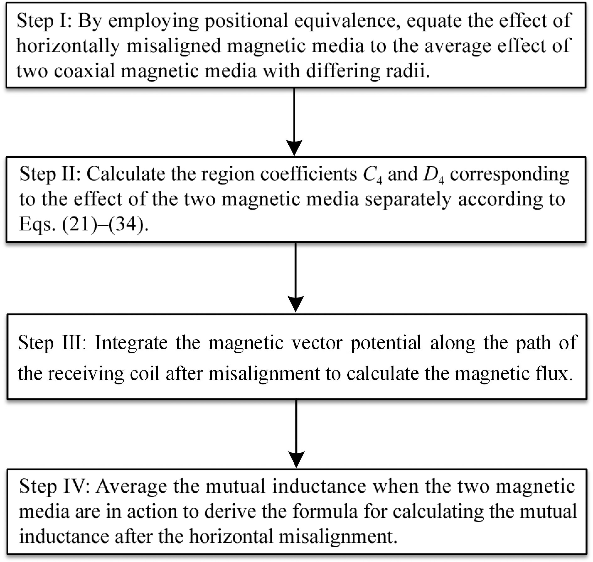
In practice, there will inevitably be a horizontal misalignment on the receiving side of a wireless energy transmission system. Due to the presence of a magnetic medium on the receiving side, the horizontal misalignment will destroy the cylindrical symmetry of the model, making it impossible to continue to calculate the mutual inductance value using the original method. Therefore, this section proposes a positional equivalence method for deriving the mutual inductance calculation formula for horizontal misalignment. Figure 4 illustrates the four steps of calculating the mutual inductance for horizontal misalignment using the positional equivalence method.
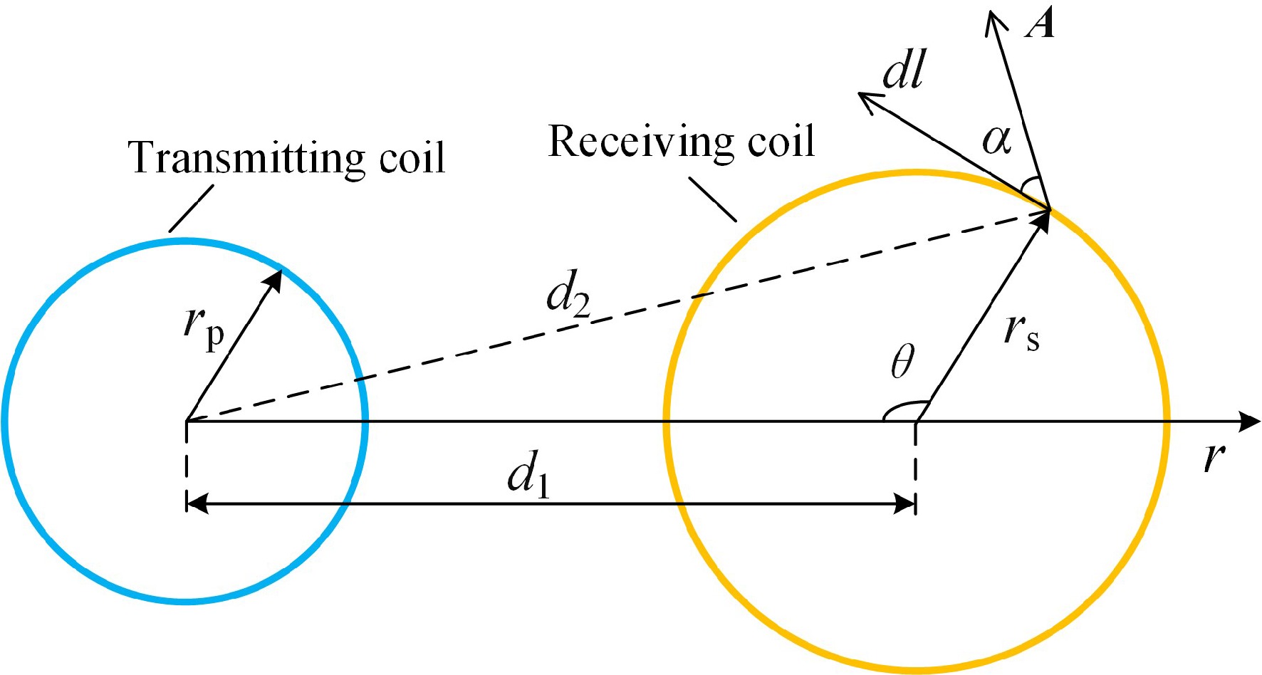
For the model proposed in this paper, when the horizontal misalignment distance is d1, the model misalignment diagram is shown in Fig. 5.
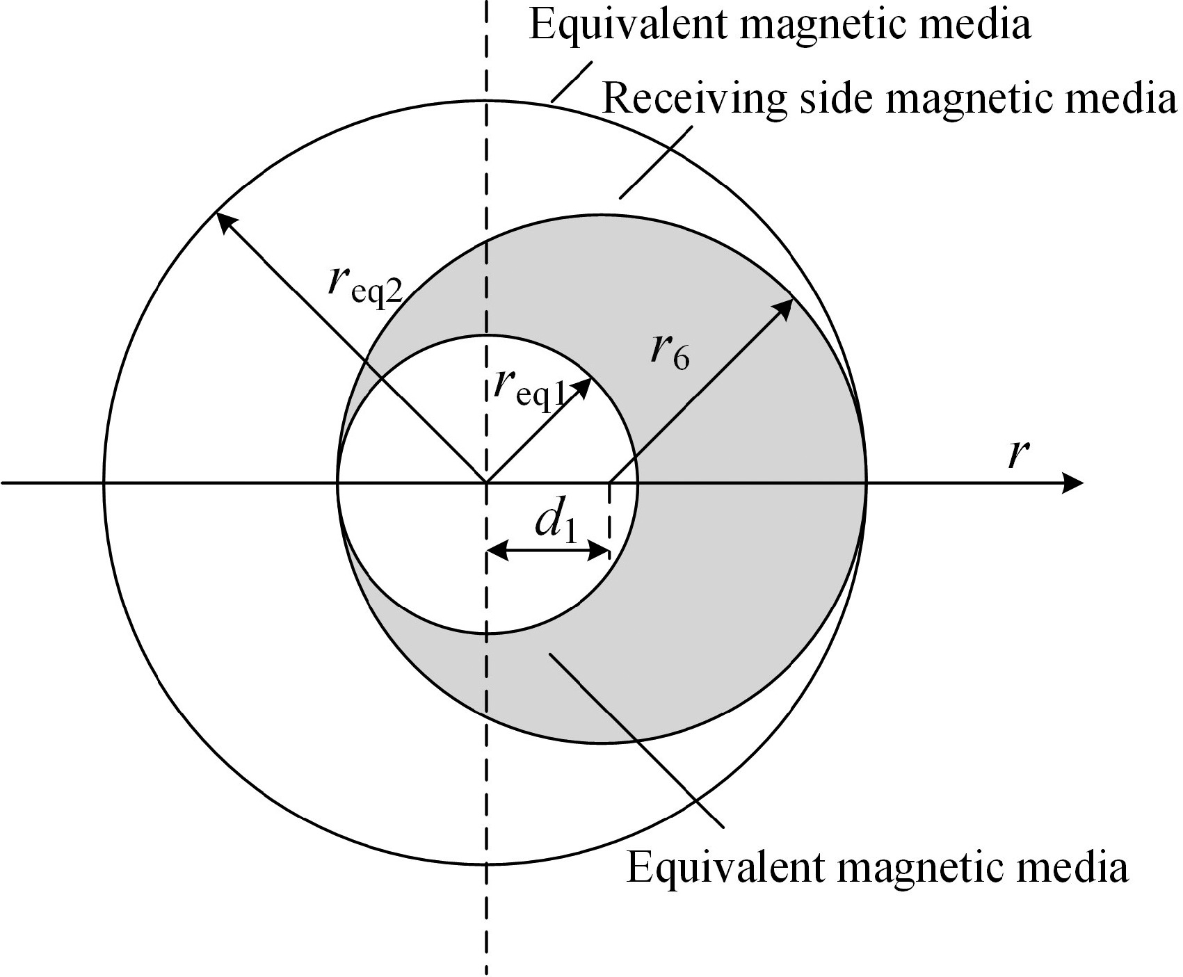
The principle of the position equivalence method is to equivalently represent the effect of the magnetic medium on the receiving side after horizontal displacement as the average effect of two magnetic media positioned coaxially with different radii. This magnetic medium structure serves as a substitute for disc-type magnetic medium structures, so only the equivalence of the magnetic medium's outer radius needs to be considered. The equivalent process of a magnetic medium with an outer radius of r6 is illustrated in Fig. 6. req1 represents the radius of the magnetic medium after equivalence, which is smaller, and req2 represents the radius of the magnetic medium after equivalence, which is larger. The magnetic material remains the same before and after equivalence.
The above equivalent process coordinate relationship can be described by Eqn (41):
$ \left[ {\begin{array}{*{20}{c}} {{r_{\rm eq1}}} \\ {{r_{\rm eq2}}} \end{array}} \right] = \left[ {\begin{array}{*{20}{c}} 1&{ - {d_1}} \\ 1&{{d_1}} \end{array}} \right]\left[ {\begin{array}{*{20}{c}} {{r_6}} \\ 1 \end{array}} \right] $ (41) Replace r6 with the equivalent magnetic medium radii req1 and req2 in turn, and reintroduce them into the above system of Eqns (21)−(34) according to the steps, which can be solved for the new area coefficients C4 and D4, respectively.
Figure 7 illustrates a top view of the transmitting coil and the receiving coil at a horizontal misalignment distance of d1. In the figure, dl represents a certain integral line element of the receiving coil, which is oriented at an angle to the magnetic vector potential of α. The angle between the radial direction over the line element and the opposite direction of the r-axis is noted as θ. d2 is the distance between the location of the transmitter coil's center of circle and the line element, which is given by the cosine equation
$ {d_2} = \sqrt {{d_1}^2 + {r_{\rm s}}^2 - 2{d_1}{r_{\rm s}}\cos\theta } $ (42) The magnetic flux of the receiving coil is the integral of A4(r, zs) along the receiving coil and the flux Φ is expressed as:
$ {\Phi}= \oint {A_4}\left( {r,{z_{\rm s}}} \right)\cos\alpha dl $ (43) The mutual inductance M between the multi-turn transmitting coil and the multi-turn receiving coil at horizontal misalignment is:
$ M = \dfrac{1}{I}\sum\limits_{m = 1}^{N_{\rm p}} {\sum\limits_{s = 1}^{N_{\rm s}} {\sum\limits_{i = 1}^n {\int_0^{2\pi } {{J_1}\left( {{k_i}r} \right)} } } } \left( {{C_4}{{\rm e}^{{k_i}{z_{\rm s}}}} + {D_4}{{\rm e}^{ - {k_i}{z_{\rm s}}}}} \right){r_{\rm s}}\dfrac{{{{{r}}_{\rm s}} - {d_1}\cos\theta }}{{{d_2}}}d\theta $ (44) The mutual inductance Mtotal calculated after using the positional equivalence method is:
$ {M_{\rm{total}}} = \dfrac{{{M_{\rm{eq1}}} + {M_{\rm{eq2}}}}}{2} $ (45) where Meq1 and Meq2 represent the mutual inductance when two coaxial magnetic media with different radius sizes act separately after equivalence, which can be derived from Eqn (44). Equation (45) describes the expression for calculating the mutual inductance after the horizontal misalignment of the receiving side.
-
To verify the accuracy of the calculation method, the mutual inductance calculation program is written using Matlab software, and the mutual inductance calculation values are obtained. Simultaneously, the model is drawn using Ansys Maxwell finite element software and the mutual inductance simulation values are obtained. By building an experimental platform, the experimental value of the mutual inductance is obtained by using an impedance analyzer. The calculated values of mutual inductance are compared with the simulated and experimental values to analyze the errors in the three cases of different transmission distances on the receiving side, different distances with horizontal misalignment, and changes in the number of turns of the receiving coil. On this basis, this paper further compares the mutual inductance values in the case of convex toroidal media structure and disc-type media structure, the time consumed for calculating mutual inductance and simulating mutual inductance, and the differences of mutual inductance calculation methods in the domestic and foreign research literature.
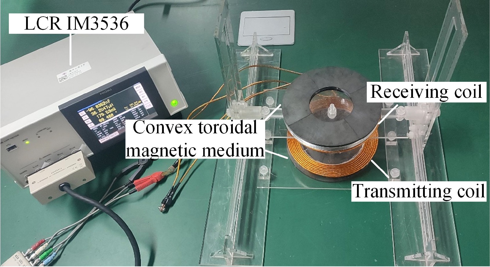
The experimental test setup built in this paper is shown in Fig. 8, and the detailed parameters of the coil and magnetic media are shown in Table 1.
Table 1. Coil and magnetic media parameters.
Parameters Value Coil radius change 0.1 mm Copper wire diameter 3 mm Height of receiving coil, zs 22−112 mm Coil to medium distance, zp 12 mm Turns of transmitting coil, Np 8 Turns of receiving coil, Ns 9 Transmitting coil inner radius, rp 62 mm Receiving coil inner radius, rs 65.1 mm Conductivity of mag. media, σ 0.01 S/m Relative permeability of mag. media, μr 2,800 Thickness of toroidal mag. media, c1 (c3) 5 mm Thickness of convex mag .media, c2 (c4) 5 mm Inner diameters of toroidal mag. media, r1 (r4) 35 mm Outer radius of toroidal mag. media, r3 (r6) 90 mm Outer radius of convex mag. media, r2 (r5) 35.15 mm Figure 9a−c shows the experimental procedure at different transmission distances on the receiving side, at different distances of horizontal misalignment, and changes in the number of turns of the receiving coil.
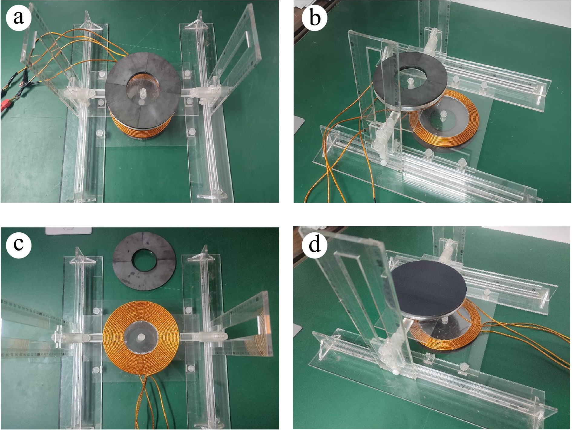
Figure 9.
Diagram of different experimental processes. (a) Transmission distance variation; (b) horizontal misalignment; (c) variation of turns; (d) disc-type comparison.
The experiment uses an impedance analyzer IM3536 for measuring the mutual inductance values. The current frequency is set to 85 kHz and the measurement principle is illustrated in Fig. 10. The specific measurement procedure is as follows: when the terminals of the receiving coil are connected forwardly with the terminals of the transmitting coil, the forward series mutual inductance L1 can be obtained as L1 = (Lp + Ls + 2M); when connected in reverse, the reverse series mutual inductance L2 can be obtained as L2 = (Lp + Ls − 2M). Wherein, Lp and Ls represent the self-inductance values of the transmitting and receiving coils respectively, and the mutual inductance value M can be calculated using the formula M = (L1 − L2)/4.

Figure 10.
Mutual inductance measurement schematic. (a) Series connection; (b) inverted series connection.
For analysis, the simulation error coefficient ɛ1 and the experimental error coefficient ɛ2 are defined as:
$ {\varepsilon _1}{\text{ = }}\dfrac{\left| M_{\rm s} - {M_{\rm c}} \right|}{ M_{\rm c}}\times 100{\text{%}} $ (46) $ {\varepsilon _2}{\text{ = }}\dfrac{\left| M_{\rm e} - M_{\rm c} \right|}{ M_{\rm c}} \times 100{\text{%}} $ (47) where, Ms is the simulated value of mutual inductance, Me is the experimental value of mutual inductance and Mc is the calculated value of mutual inductance.
Different transmission distances
-
In the experiments with different transmission distances, the receiving side was set to be placed coaxially with the transmitting side and the receiving coil and magnetic medium were moved along the z-axis positive direction in steps of 10 mm. The initial height of the receiving coil is set to zs = 22 mm, and the calculated, simulated, and experimental values of mutual inductance for Δz from 10 to 100 mm are recorded step by step. Figure 11 shows the schematic of the model at different transmission distances, and the results of the mutual inductance calculated values with the simulated and experimental error values are shown in Table 2.
Table 2. Inductance values and errors at different transmission distances.
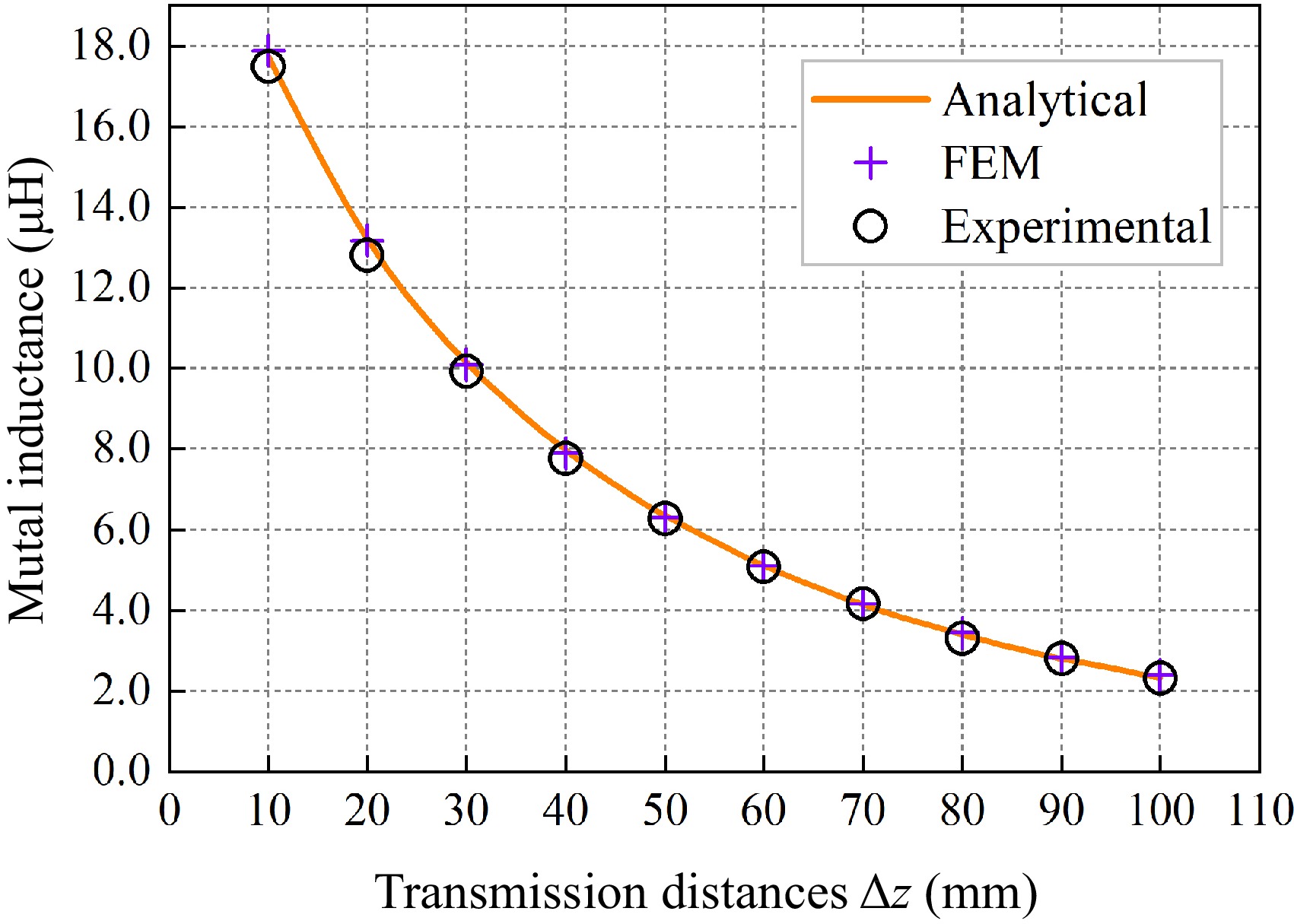
Δz (mm) Ms (μH) Me (μH) Mc (μH) ɛ1 ɛ2 10 17.8868 17.4979 17.7292 0.89% 1.30% 20 13.1848 12.8047 13.2171 0.24% 3.12% 30 10.0934 9.9253 10.1615 0.67% 2.32% 40 7.9031 7.7624 7.9721 0.87% 2.63% 50 6.3084 6.2658 6.3461 0.59% 1.26% 60 5.0976 5.0777 5.1091 0.23% 0.61% 70 4.1553 4.1702 4.1515 0.09% 0.45% 80 3.4251 3.3106 3.4004 0.73% 2.64% 90 2.8461 2.7910 2.8050 1.47% 0.50% 100 2.3817 2.3080 2.3288 2.27% 0.89% Analyzing the data in Table 2, it can be seen that when the transmission distance between the transmitting coil and the receiving coil is within 10−100 mm, the simulation error ɛ1 of the mutual inductance value is maximal at 2.27%, and the experimental error ɛ2 is maximal at 3.12%, and there is a high degree of conformity between the calculated value, the simulated value, and the experimental value.
Figure 12 shows the variation of mutual inductance values at different transmission distances plotted based on the data in Table 2. Observing Fig. 12, it can be noted that when the transmission distance between the receiving and transmitting sides is minimal, the mutual inductance reaches its maximum value. As the transmission distance increases, the mutual inductance gradually decreases. This is because as the transmission distance increases, the magnetic flux density decreases, resulting in a smaller magnetic flux in the receiving coil. Therefore, the mutual inductance is approximately inversely proportional to the transmission distance.
Horizontal misalignment at different distances
-
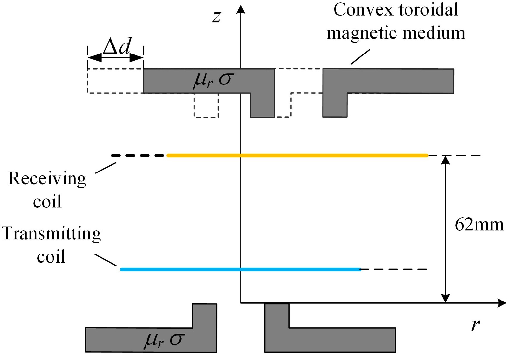
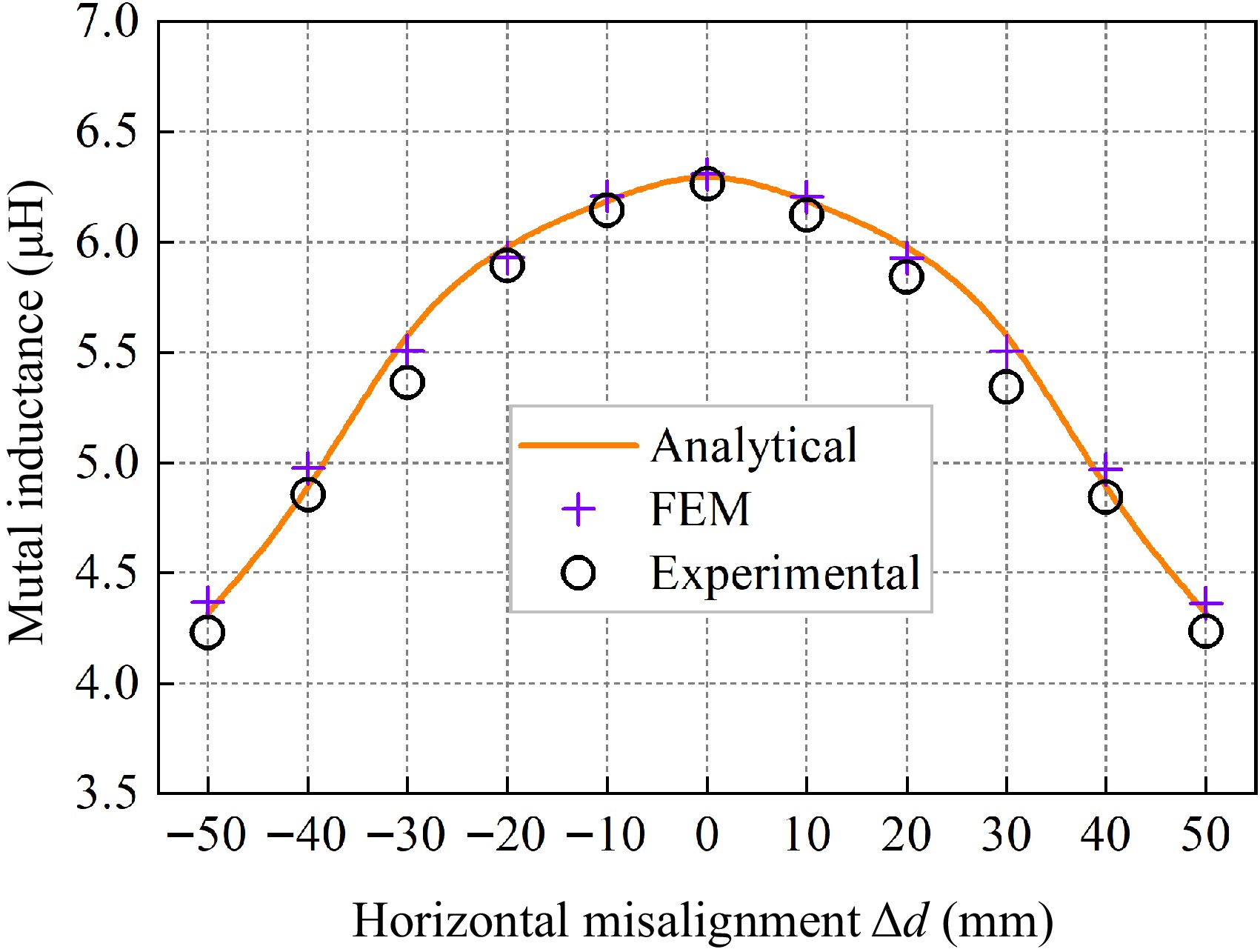
In experiments conducted at different horizontal misalignment distances, it is stipulated that the receiving and transmitting sides are coaxially aligned, and the receiving coil and magnetic medium are moved along the horizontal direction with a step size of 10 mm. The initial height of the receiving coil is fixed at z2 = 62 mm, and the mutual inductance values are recorded gradually as Δd ranges from −50 to 50 mm. Figure 13 illustrates the schematic diagram of the model at different horizontal misalignment distances, and the error results between the calculated mutual inductance values and the simulated and experimental values are shown in Table 3.
Table 3. Inductance values and errors at horizontal misalignment.
Δd (mm) Ms (μH) Me (μH) Mc (μH) ɛ1 ɛ2 −50 4.3656 4.2280 4.3171 1.12% 2.06% −40 4.9752 4.8559 4.8450 2.69% 0.23% −30 5.5096 5.4329 5.6536 2.55% 3.90% −20 5.9312 5.8920 6.0063 1.25% 1.90% −10 6.2088 6.1459 6.1930 0.26% 0.76% 0 6.3084 6.2658 6.3461 0.59% 1.26% 10 6.2060 6.1259 6.1930 0.21% 1.08% 20 5.9287 5.8404 6.0063 1.29% 2.76% 30 5.5065 5.4160 5.6536 2.60% 4.23% 40 4.9683 4.8462 4.8450 2.55% 0.03% 50 4.3630 4.2359 4.3171 1.06% 1.88% Analyzing the data in Table 3, it can be seen that when the horizontal misalignment distance of the receiver side is within −50 to 50 mm, the simulation error ε1 of the mutual inductance value is 2.69% at maximum, and the experimental error ε2 is 4.23% at maximum, and the mutual inductance calculated value shows good consistency with the simulation and experimental values.
Figure 14 is a graph of the variation of mutual inductance values at different distances of horizontal misalignment. Observing Fig. 14, it can be seen that when the height of the receiving coil is kept constant at 62 mm, the mutual inductance value is in a left-right symmetric shape about the horizontal misalignment distance of the receiving side. The mutual inductance value reaches the maximum when the misalignment distance along the horizontal of the receiving side is the smallest. With the increase of the horizontal misalignment distance, the mutual inductance value decreases gradually. This is because the magnetic field distribution makes the magnetic flux across the receiving coil is smaller when the horizontal misalignment distance is larger, resulting in the mutual inductance value showing a decreasing trend.
Variation of turns
-
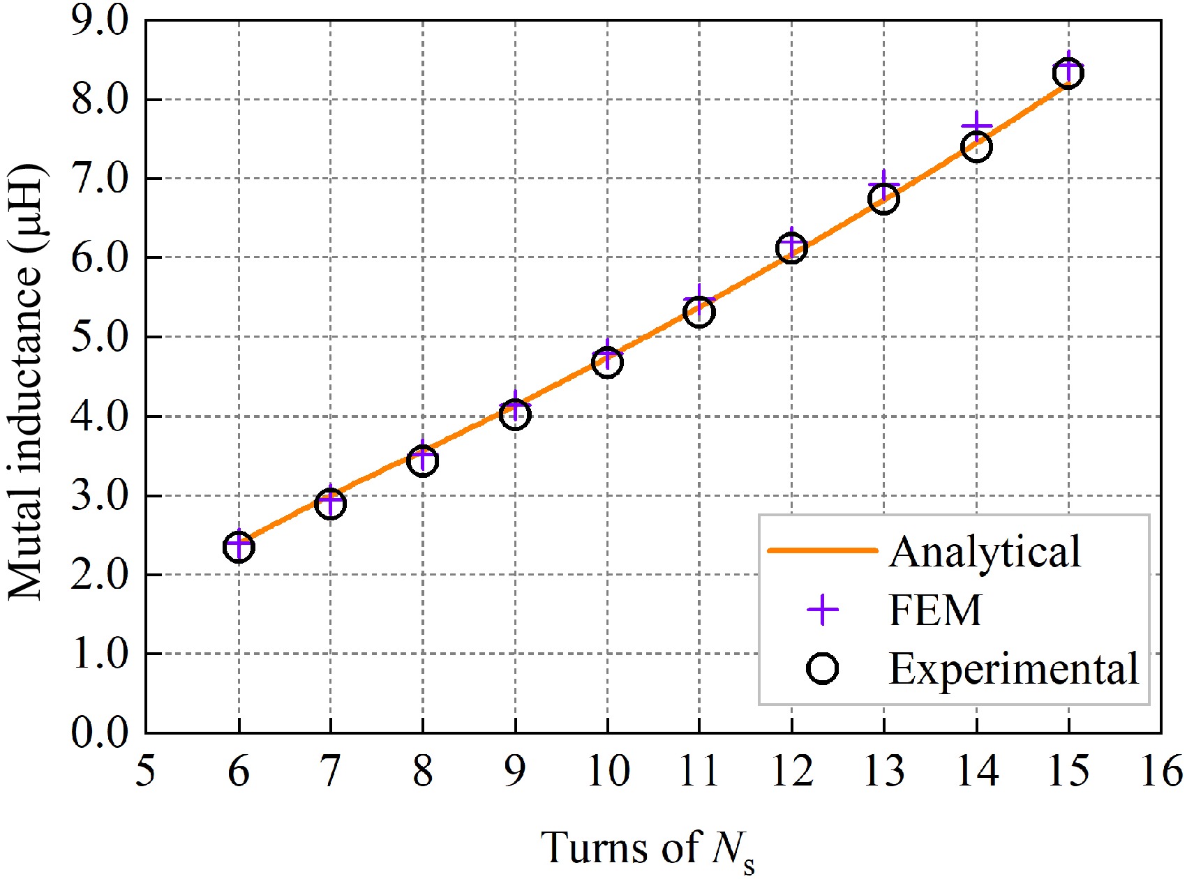
The inner radius rs of the receiving coil was set to 40 mm, the number of turns of the receiving-side coil was changed, and other parameters were kept consistent with Table 1. The mutual inductance value of the receiving coil is measured when the number of turns Ns is varied from six turns to 15 turns at the transmission distance Δz = 50 mm. Table 4 shows the error analysis of the calculated values of mutual inductance with respect to the simulated and experimental values when the number of turns is varied.
Table 4. Mutual inductance values and errors when changing the number of Ns.
Ns Ms (μH) Me (μH) Mc (μH) ɛ1 ɛ2 6 2.3982 2.3454 2.3927 0.23% 1.98% 7 2.9411 2.9163 3.0137 2.41% 3.23% 8 3.5225 3.4263 3.5554 0.93% 3.63% 9 4.1412 4.0136 4.1311 0.24% 2.85% 10 4.7921 4.6726 4.7387 1.13% 1.39% 11 5.4730 5.3113 5.3760 1.80% 1.20% 12 6.1956 6.1184 6.0401 2.57% 1.30% 13 6.9220 6.7356 6.7283 2.88% 0.11% 14 7.6679 7.4002 7.4462 2.98% 0.62% 15 8.4281 8.3281 8.1980 2.81% 1.59% Analyzing the data in Table 4, it can be seen that the simulation error ε1 of the mutual inductance value does not exceed 2.98% and the experimental error ε2 does not exceed 3.63% when the number of turns of the coil on the receiving side is varied, and the mutual inductance calculation value shows good consistency with the simulation and experimental values. Based on the data in Table 4, the variation curves of mutual inductance values for the number of turns of the coil on the receiving side from six turns to 15 turns when the transmission distance is 50 mm are plotted, as shown in Fig. 15.
Analyzing Fig. 15 shows that the slope of the mutual inductance value vs the number of turns varies with a slight upward trend. This is because, as the number of turns of the receiving coil increases, not only does the magnetic chain increase proportionally, but also the coupling area between the receiving side and the transmitting side increases due to the helical winding structure of the coil, increasing the slope.
Comparison of mutual sense when convex ring structure and disc-type structure
-
The magnetic media proposed in this paper adopts a convex toroidal structure, which can save nearly 15% of the magnetic media material compared with the disc-type magnetic media of the same specification. To compare the differences in the effects of the two magnetic media structures on mutual inductance with the same coil shape, experimental models of convex toroidal and disc-type magnetic media are established using the parameters in Table 1. The experimental data of the two models are measured for the horizontal misalignment distance Δd = 25 and 50 mm cases on the receiver side and Δz changes from 0 to 100 mm, respectively, and the mutual inductance scaling factor is defined:
$ \gamma {\text{ = }}\dfrac {{M_{{\rm e1}}}}{{M_{{\rm e2}}}} \times 100{\text{%}} $ (48) where, Me1 is the experimental mutual inductance value for the convex toroidal magnetic medium structure and Me2 is the experimental mutual inductance value for the disc-type magnetic medium structure. The experiments for both are conducted under the conditions depicted in Fig. 16, with the experimental setup shown in Fig. 9d.
The corresponding experimental mutual inductance values and proportion coefficients between the convex toroidal structure and the disc-type structure are listed in Table 5. The data in Table 5 show that when the horizontal misalignment distance Δd = 25 mm on the receiving side, the mutual inductance under the convex toroidal dielectric structure can reach more than 98.26% of the mutual inductance of the disc-type dielectric structure. When the horizontal misalignment distance is increased to 50 mm, the mutual inductance data of the two structures are still close to each other, and the mutual inductance of the convex toroidal dielectric structure can reach more than 97.75% of the mutual inductance of the disc-type media structure. The mutual inductance comparison data in Table 5 can be described by a scatter plot, as shown in Fig. 17.
Table 5. Corresponding mutual inductance values and errors for two magnetic media structures.
Δz (mm) Δd = 25 mm Δd = 50 mm Me1 (μH) Me2(μH) γ Me1(μH) Me2(μH) γ 10 14.4329 14.6878 98.26% 9.0775 9.0925 99.84% 20 11.1521 11.31451 98.56% 7.4525 7.6125 97.90% 30 8.7612 8.6462 98.67% 6.0875 6.1975 98.23% 40 7.1582 7.2475 98.77% 5.2530 5.2925 99.25% 50 5.6380 5.7125 98.70% 4.2377 4.3170 98.16% 60 4.5627 4.6144 98.88% 3.5525 3.6344 97.75% 70 3.7967 3.8312 99.10% 2.9925 3.0250 98.93% 80 3.1946 3.2271 98.99% 2.5226 2.5558 98.70% 90 2.5934 2.6147 99.19% 2.1061 2.1232 99.19% 100 2.1293 2.1637 98.41% 1.8254 1.8325 99.61% 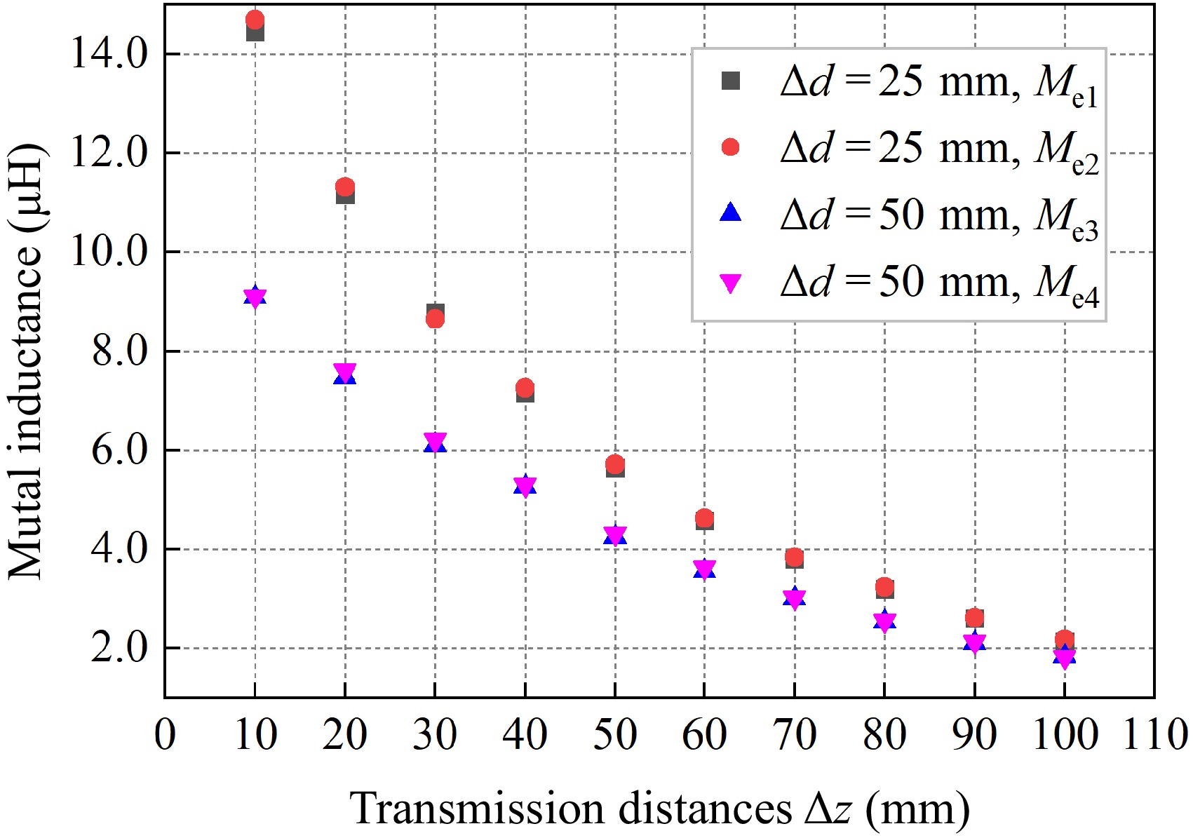
Figure 17.
Comparison of inductance between convex toroidal and disc-type magnetic media structures.
Analyzing Table 5 & Fig. 17, it can be seen that with the convex toroidal magnetic media being able to save nearly 15% of the magnetic media material, for different transmission distances and horizontal misalignment distances, the convex toroidal structure can achieve a similar effect as the disc-type structure in terms of mutual inductance enhancement, which reflects the superiority of the convex toroidal magnetic media structure.
Time comparison
-
With the same computer hardware configuration (CPU: i5-13600k, RAM: 16GB), the mutual inductance values of the same parameter model were obtained using the Matlab program and Maxwell simulation software for different transmission distances, different horizontal misalignment distances and coil turns variations. Table 6 records the comparative data of the time taken by both excluding the model building time.
Table 6. Calculating the average time required for mutual inductance.
Experiment type Algorithm time (s) Simulation time (s) Transmission distances 3.102 237.2 Horizontal misalignment 3.375 245.4 Adding one more coil 0.047 13.35 Analyzing the data in Table 6 reveals that for different transmission distances and different horizontal misalignment tests, the average time required for simulation is 237.2 s, while the longest average time required using the provided algorithm is 3.375 s. This indicates that the calculation speed using the algorithm is approximately 70 times faster than the simulation. In the test with varying numbers of turns, adding one turn to the coil increases simulation time by 13.35 s, while the algorithm time only increases by 0.047 s. Therefore, the method proposed in this paper demonstrates a significant advantage in mutual inductance calculation speed.
Comparison of mutual sense calculation methods in the national and international research literature
-
The model calculation method proposed in this paper is compared with other domestic and international literature, and the comparison results are shown in Table 7.
Table 7. Comparison of mutual inductance calculation methods with other literature.
Method DTD DHMD MM FMS DS MS ERR Ref. Elliptic integral √ √ × × × × / [12] Bessel integral √ √ × × × × / [13] Euler angles √ √ × × × × / [15] Fourier-Bessel transform √ √ √ × √ × / [17] Coordinate transformation method √ √ √ √ × × 4.78% [18] Truncation domain division √ √ √ √ × × 4.76% [20] Magnetic circuit magnetic resistance theory √ × √ √ √ × 8.13% [21] Magnetic vector potential position equivalence method √ √ √ √ √ √ 4.23% This study DTD: different transmission distances; DHMD: different horizontal misalignment distances; MM: magnetic medium; FMS: finite magnetic medium; DS: double side; MS: Material Saving; ERR: Error. DS means the magnetic medium is bilateral case, MS means saving the magnetic medium material, ERR means the maximum calculation error. Table 7 shows that the proposed magnetic vector position equivalence method in this paper can effectively calculate the mutual inductance in wireless power transfer systems containing bounded magnetic media, relative to studies by Babic et al.[12], Conway[13], Liu et al.[15], and Liu et al.[17]. Additionally, compared to studies by Zhang et al.[18] and Chen et al.[20], it can calculate mutual inductance in systems containing bilateral bounded magnetic media. Furthermore, compared to reference[21], it can calculate the mutual inductance on the receiving side with a horizontal misalignment of bilateral bounded magnetic media. Moreover, only the method proposed in this paper can effectively calculate mutual inductance while saving bilateral magnetic media materials, and the maximum error is 4.23%, which is within the acceptable range.
-
This paper proposes a method of magnetic vector potential position equivalence and derives analytical solutions for mutual inductance of circular coils with bilateral bounded convex magnetic material rings. This method is based on Maxwell's equations and boundary conditions, utilizing the magnetic vector potential to derive the mutual inductance calculation formula for the coaxial case. Building upon this, the method employs the position equivalence approach to derive the mutual inductance calculation formula for horizontal misalignment.
Through verification on both finite element simulation and experimental platforms, it is demonstrated that the mutual inductance calculation errors for different transmission distances, various horizontal misalignments and changes in the number of turns do not exceed 4.23%. Additionally, the computational speed is 70 times faster than simulation, affirming the effectiveness and efficiency of the proposed method. Under equivalent specifications, the proposed model structure can save 15% of material compared to using a disc-type magnetic material structure.
The proposed mutual inductance calculation method can be used for the design and optimization of coil parameters in wireless power transfer systems, and the proposed convex annular magnetic dielectric structure can be used in penetrating wireless power transmission scenarios such as pipelines.
-
The authors confirm contribution to the paper as follows: study conception and design: Hu C, Li Z; data collection: Hu C, Kong L; analysis and interpretation of results: Hu C, Wang J; draft manuscript preparation: Hu C, Zhang C. All authors reviewed the results and approved the final version of the manuscript.
-
The datasets generated during the current study are available from the corresponding author on reasonable request.
This research is partially funded by National Key R&D Program of China (2022YFB3403200), Hunan Provincial Department of Education Key Project (23A0432), Hunan Provincial Natural Science Foundation (2022JJ30226), Outstanding Youth Project of Scientific Research Program of Hunan Provincial Department of Education (22B0577) and National Natural Science Foundation of China Youth Science Fund Project (62303178).
-
The authors declare that they have no conflict of interest.
- Copyright: © 2024 by the author(s). Published by Maximum Academic Press, Fayetteville, GA. This article is an open access article distributed under Creative Commons Attribution License (CC BY 4.0), visit https://creativecommons.org/licenses/by/4.0/.
-
About this article
Cite this article
Hu C, Li Z, Kong L, Wang J, Zhang C. 2024. Calculation method of mutual inductance of circular coils with bilateral convex toroidal magnetic medium in WPT system with horizontal misalignment. Wireless Power Transfer 11: e004 doi: 10.48130/wpt-0024-0004
Calculation method of mutual inductance of circular coils with bilateral convex toroidal magnetic medium in WPT system with horizontal misalignment
- Received: 05 May 2024
- Revised: 15 July 2024
- Accepted: 02 August 2024
- Published online: 03 September 2024
Abstract: Accurately calculating mutual inductance is crucial for achieving efficient and reliable wireless power transfer systems. However, when horizontal displacement occurs in double-sided magnetic coils, the mutual inductance values are typically obtained using finite element software, lacking a simple analytical formula for calculation. Additionally, magnetic materials are costly, and there's still room for optimizing disc-type magnetic structures. Therefore, this paper proposes a magnetic vector potential position equivalent method and derives an analytical solution for mutual inductance of circular coils with bilateral convex toroidal bounded magnetic media. The magnetic vector potential in each region can be derived, based on Maxwell's equations and combined with boundary conditions. Utilizing the position equivalent method enables rapid calculation of mutual inductance for coaxial and horizontally displaced scenarios on the receiving end. Comparison between calculated mutual inductance values and finite element simulation, along with experimental measurements, demonstrates an error within 4.23% and a calculation speed 70 times faster than simulation. Experimental validation shows that the mutual inductance of the convex toroidal magnetic structure can reach more than 97.75% of the mutual inductance of the disc-type magnetic structure while saving 15% of magnetic material.


