


-
Traditional artificial catheterization implants a plastic drain into the urethra of the patient where the end of the drain is left outside the patient's body[1]. The infection is commonly inevitable for traditional catheterization because germs will get access to the patient's urethra as well as bladder through the internal drain. Alternatively, implanting an electromagnetic valve into the urethra to control urination can avoid inflammation. However, to power the valve implant inside the urethra is difficult. Hence, WPT is proposed to solve the power supply problem.
Nowadays, WPT has become prevalent in many implant devices, such as heart pacemakers, artificial cochlea, artificial hearts, and so on[2−5]. Compared with traditional methods, WPT transfers energy without metal wires, which provides the best solution for the power supply of implant devices inside the human body. For the WPT suppling electromagnetic valve implanted in the urethra, however, the distance between the transmission coil and the receiving coil is large compared to the diameter of the urethra embedding the receiving side. The diameter of the urethra is commonly smaller than 10 mm for both males and females. Additionally, cutting into the patient's skin or urethral wall is unacceptable. The former is for convenience of use, while the latter is to avoid infection.
Hence, a relay is necessary for the WPT to transfer enough power suppling the electromagnet[6−9]. In Zhao et al.[6], a mutual inductance identification method is proposed to analyze the mutual inductances among the sending, relay, and receiving coils via the switchable relay coil, and the relay is turned on or off according to the system efficiency with and without the relay coil when the load resistance or position varies. Previous literature[7] proposed an efficiency improvement method which operates the WPT under non resonant compensation status for relay-based systems. To describe and explain the interaction among multiple relay coils, a method named the transfer coefficient model (TCM) is proposed based on cross-coupling effects in the literature[8]. An optimization design method for further improving the efficiency of the three-coil WPT system by tuning the compensation capacitor of the relay coil is proposed in previous literature[9]. In previous research, multiple coils are the same type, such as planar spiral coil. Commonly, all the same-type coils constituting the relay are set face-to-face, or with a small angle, to enhance the mutual inductance.
The wired relay instead of the wireless relay, however, is the best choice for the proposed WPT for the art catheterization system. There is mainly due to two reasons:
First, a solenoid coil is the best choice due to the small available diameter inside the urethra. Commonly, the diameter of the urethra is below 8 mm, which is very limited to place a planar coil. However the length of the urethra is 3 to 8 cm for females, and 15 to 25 cm for males. To obtain a suitable inductance in the long and narrow space, a solenoid coil is the best choice to make full use of the length of the urethra. For the sending coil, however, a planar spiral coil is more appreciable to save space.
Second, the solenoid coil is not suitable to receive power wirelessly from the planar coil. Because the coupling between different types of coils is very weak. Hence, a wired relay instead of the wireless relay is employed to transfer power between different types of coils for the catheterization system. A wireless relay coil can be inserted between the sending coil and the first wired relay coil, but the additional relay inevitably decreases the whole efficiency.
As a result, a two-coil wired relay with LLC compensated topology is proposed to transfer power between the sending coil and the receiving coil. The first relay coil coupling with the sending coil employees the solenoid type, while the second relay coil coupling with the receiving coil choosing a planar spiral coil.
The maximum power as well as maximum efficiency is the target of many existing literature for WPT[6−9]. For the case of artificial catheterization, the required power is below 1 W and can be increased further by employing a DC source with a higher voltage. Hence, the power is not a key issue for the current case. For efficiency, however, a lower efficiency leads to a higher power dissipation. Thermal loss in the human body leads to serious discomfort. Hence, the efficiency should be improved to decrease power loss generating heat. Additionally, the regulated power supply at the receiving side for traditional applications is preferred to be canceled as the available space in the urethra is very limited. Hence, the electromagnetic valve equivalent resistance can be optimized for the highest efficiency without considering the regulated power supply. The electromagnetic valve whose equivalent resistance is the optimized one is chosen to obtain the highest efficiency. Pinuela et al.[10] put forward a strategy to improve the compatibility and performance of the WPT system based on the Q-learning algorithm and switch-controlled-capacitor (SCC) under various loads or mutual inductances to obtain the highest efficiency. Zhang et al.[11] proposes an efficiency improvement method with a class-E inverter and copper coil with a high-quality factor. Deng et al.[12] assumes the coil quality factor determines the possible maximum efficiency. Additionally, Deng et al.[12] proposes a method to predict the maximum efficiency based on the coil quality factor, and the corresponding optimized load resistance at the receiving side. Previous literature[13−15] analyzes the coil frequency-dependent resistance and derives the optimized operation frequency for the highest efficiency. However, the above mentioned literature focus on the two-coil WPT instead of three-coil or more where the parameter of the relay coil is not accounted for. The P-LCC-S topology proposed here is more complex regarding efficiency optimization and needs further research.
As to the WPT dedicated for artificial catheterization, the key issue is that the space is limited for the relay and receiving coils. The present study designs the coils deliberately considering the space limitation, and optimizes the load resistance as well as inverter operation frequency for the highest efficiency. The electromagnetic safety of WPT is another key issue for its practical application in the human body. There are three parameters to assess the human exposure to EMFs from WPT systems, current density (J), internal electric field (E), and/or specific absorption rate (SAR). Currently, there are many research articles regarding EMF evaluation of WPT for implanted devices[16−18]. As mentioned by these studies, the lower operation frequency (below 1 MHz) as well as the lower transferred power contribute to decreasing the negative effect of WPT on the human body. For the current proposed system, its operation frequency is below 1 MHz and the transferred power is about 0.6 W, which are far below than those in the literature[16], 6.78 MHz and 50 W, respectively. Hence, the SAR is not detailed in this paper. The specific contributions of this paper are as follows:
a) A wired relay with two coils is proposed to transmit power between different type of coils of the sending and receiving sides. The mutual inductances are enhanced because the same coil type is used as to each coupling coil group.
b) The efficiency optimization method regarding the equivalent load resistance of the electromagnetic valve as well as the operation frequency are proposed for the highest transfer efficiency.
-
The proposed P-LCC-S topology WPT is shown in Fig. 1. The schematic of the installation of the whole system is depicted in Fig. 1a. It consists of three parts, the sending module, the relay module, and the receiving module. The sending module is outside of the human body. The relay module mainly consists of two relay coils connected with wire. The first relay coil is buried beneath the subcutaneous fat layer while the second relay coil wraps around the outside of the urethra. The components of the receiving module are inserted into a hollow cylindrical shell. The installation schematic of the receiving module is shown in Fig. 1b. The shell is then embedded in the urethra.
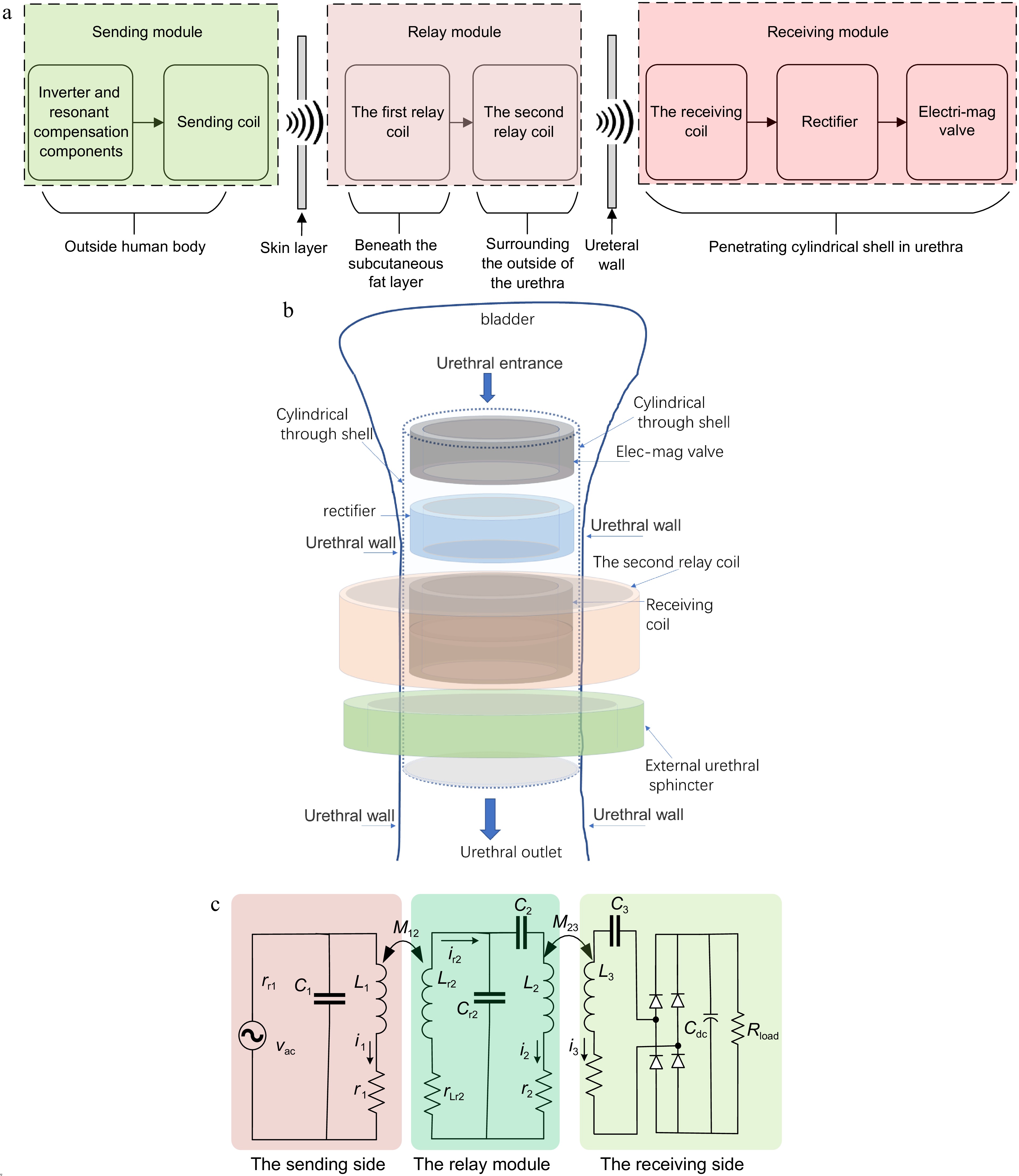
Figure 1.
Schematic diagram of the proposed system based on P-LCC-S topologic WPT. (a) Installation schematic of the whole system. (b) Installation schematic of the receiving module. (c) Circuit topology.
The circuit topology is shown in Fig. 1c. In the case of application, the sending coil is difficult to align exactly with the first relay coil. A parallel compensated topology is therefore employed for the sending module to suppress the possible overcurrent where a relatively high impedance of L1 is employed. The relay module transfers the power from the sending coil L1 to the receiving coil L3. The AC power vac is an equivalent output of the inverter powered by a DC source at the sending side. L1 and L3 are the sending coil and the receiving coil, respectively, while Lr2 and L2 are used as the relay coils. Resonant capacitors Cr1, C1, Cr2, C2, and C3 are employed to compensate for the impedances for various coil inductances, respectively. Two groups of mutual inductances are depicted as M12 and M23, which reflects the wireless power transfer capacity through the human skin and the urethra wall, respectively. The Root Mean Square (RMS) values of resonant currents through various resonant loops are i1, ir2, i2, and i3, respectively. The parasitic resistances are r1, rr2, r2, and r3 for the inductor L1, Lr2, L2, and L3, respectively. A rectifier transfers the AC to DC and Cdc is the filter capacitor at the receiving side. The load of the rectifier is Rload. For the application of artificial catheterization, the load resistance is equal to that of the electromagnetic valve.
There are other possible selections for relay module compensated topology, for example, a series compensation topology. The LLC topology, however, can obtain a higher efficiency for this case. For a fair comparison, one obtains a series compensation topology while canceling the resonant capacitor CR2 and tuning the capacitance of C2 to realize the series resonant status in Fig. 1c. For both the series topology and LCC topology, one needs the same current i2 through L2 to transfer the same power to the receiving side. For the typical LCC topology, the current ir2 through the inductor Lr2 is far lower than that of i2 through L2. For the series topology, however, ir2 is equal to i2. The relay with LCC topology shows a lower loss and resulting a higher efficiency than with series topology for this application case.
For the receiving module, the LCC-topology, parallel-compensation topology and others are the possible selections. As to the LCC topology, however, an additional resonant inductor and a compensated capacitor are needed, which increases the installation difficulty considering all the components should be embedded in the human body. Employing as few components as possible is preferred. Hence, the series-compensation or the parallel-compensation topology is the best choice. Additionally, the WPT with the series-compensation at the secondary side shows a higher efficiency than that with parallel-compensation, the series one is used for the proposed WPT system at the receiving side[19]. In summary, the P-LCC-S topology WPT is employed for artificial catheterization.
Parameter design
-
Although lower r1, r2, and r3, as well as a moderately high
$ \omega $ Another issue is that the length of the second relay coil L2 should be as small as possible. This is because surgery encircling the urethra must be conducted to embed the coil L2 and a smaller length means a shorter surgical wound. Hence, a 2-layer solenoid coil is used for the coil L2. To decrease the resistance of L2, a bigger Litz wire than that of L3, namely, 0.07 mm × 50 strands is employed. Typically, a solenoid coil with a length of 17 mm and a diameter of 11 mm yields an inductance of 4.87 uH.
For the first relay coil Lr2, its size is as small as possible because a small coil means a smaller surgical incision. Hence, a two-layer flat spiral coil with a diameter of 20 mm is employed. The coil Lr2 was wound by a Litz wire of 0.07 mm × 50 strands leads to an inductance of 4.10 uH.
Performance analysis
-
Based on the design strategy of LLC topology[20], the relay module are designed as:
$ j\omega {L_{r2}} + 1/\left( {j\omega {C_{r2}}} \right) = 0 $ (1) $ j\omega {L_2} + 1/\left( {j\omega {C_2}} \right) + 1/\left( {j\omega {C_{r2}}} \right) = 0 $ (2) For the receiving module, one obtains:
$ j\omega {L_3} + 1/\left( {j\omega {C_3}} \right) = 0 $ (3) Based on KVL/KCL principles, one obtains from Fig. 1:
$ \begin{gathered} \left( {j\omega {L_1} + {r_1}} \right){i_1} + j\omega {M_{12}}{i_{r2}} = {v_{{\text{a}}c}} \\ \left( {j\omega {L_{r2}} + {r_{r2}}} \right){i_{r2}} + 1/\left( {j\omega {C_{r2}}} \right) \cdot \left( {{i_{r2}} - {i_2}} \right) + j\omega {M_{12}}{i_1} = 0 \\ 1/\left( {j\omega {C_{r2}}} \right) \cdot \left( {{i_{r2}} - {i_2}} \right) = j\omega {M_{23}}{i_3} + \left( {j\omega {L_2} + 1/\left( {j\omega {C_2}} \right) + {r_2}} \right){i_2} \\ \left( {j\omega {L_3} + {r_3} + 1/\left( {j\omega {C_3}} \right) + {R_{input}}} \right){i_3} + j\omega {M_{23}}{i_2} = 0 \\ \end{gathered} $ (4) where, Rinput is the equivalent resistance seen from the input side of the rectifier, namely,
$ {R_{input}} = \dfrac{{8{R_{load}}}}{{{\pi ^2}}} $ (5) Substitution of Eqn (2) and (3) into Eqn (4) yields:
$ \begin{gathered} \left( {j\omega {L_1} + {r_1}} \right){i_1} + j\omega {M_{12}}{i_{r2}} = {v_{ac}} \\ {r_{r2}}{i_{r2}} - 1/\left( {j\omega {C_{r2}}} \right) \cdot {i_2} + j\omega {M_{12}}{i_1} = 0 \\ 1/\left( {j\omega {C_{r2}}} \right) \cdot {i_{r2}} = j\omega {M_{23}}{i_3} + {r_2}{i_2} \\ \left( {{r_3} + {R_{input}}} \right){i_3} + j\omega {M_{23}}{i_2} = 0 \\ \end{gathered} $ (6) For the typical LCC compensated topology, the current through Lr2 is far below those through L2, namely, losses in rr2 can be ignored. Hence, currents can be extracted from Eqn (6) and simplified when rr2 are ignored,
$ {i_1} = \dfrac{{{v_{ac}}}}{Z} $ (7-1) $ {i_2} = \dfrac{{ - {v_{input}}({C_{r2}}{M_{12}}{\omega ^2})}}{Z} $ (7-2) $ {i_3} = \dfrac{{{v_{input}}\dfrac{{j{\omega ^3}{C_{r2}}{M_{12}}{M_{23}}}}{{{r_3} + {R_L}}}}}{Z} $ (7-3) where,
$ Z = {r_1} + j\omega {L_1} + C_{r2}^2M_{12}^2{\omega ^4}{r_2} + \dfrac{{C_{r2}^2M_{12}^2M_{23}^2{\omega ^6}}}{{{r_3} + {R_L}}} $ (8) -
The target of the current paper is to find an optimized input resistance Rload as well as the corresponding system operation frequency to obtain the highest transfer efficiency. To simplify the analysis, the losses in the inverter are ignored as it is relatively small compared with that in the inductors. Additionally, the loss in the resonant inductor of Lr2 is also ignored as the current through it is much smaller than that of L2, and the parasitic of it is also lower than that of L2. As a result, the system efficiency can be approximately evaluated by:
$\begin{split} \eta =\;& \dfrac{{{P_{RL}}}}{{{P_{total}}}} = \dfrac{{{{\left| {{i_3}} \right|}^2}{R_L}}}{{{{\left| {{i_1}} \right|}^2}{r_1}{\text{ + }}{{\left| {{i_2}} \right|}^2}{r_2}{\text{ + }}{{\left| {{i_3}} \right|}^2}\left( {{r_3}{\text{ + }}{R_L}} \right)}}\\ =\;& \dfrac{1}{{{{\left| {\dfrac{{{i_1}}}{{{i_3}}}} \right|}^2}\dfrac{{{r_1}}}{{{R_L}}}{\text{ + }}{{\left| {\dfrac{{{i_2}}}{{{i_3}}}} \right|}^2}\dfrac{{{r_2}}}{{{R_L}}}{\text{ + }}\left( {\dfrac{{{r_3}}}{{{R_L}}}{\text{ + }}1} \right)}} \end{split} $ (9) Substitution of Eqn (7) into Eqn (9) leads to:
$ \eta = \dfrac{1}{{{{\left( {\dfrac{{\left( {{r_3} + {R_L}} \right)}}{{{\omega ^3}{C_{r2}}{M_{12}}{M_{23}}}}} \right)}^2}\dfrac{{{r_1}}}{{{R_L}}}{\text{ + }}{{\left( {\dfrac{{\left( {{r_3} + {R_L}} \right)}}{{\omega {M_{23}}}}} \right)}^2}\dfrac{{{r_2}}}{{{R_L}}}{\text{ + }}\left( {\dfrac{{{r_3}}}{{{R_L}}}{\text{ + }}1} \right)}} $ (10) For the sending coil and the relay coil Lr2, the mutual inductance M12 is:
$ {M_{12}} = {k_{12}}\sqrt {{L_1}{L_{r2}}} $ (11) Substitution of Eqns (1) and (11) into Eqn (10) yields:
$ \eta {\text{ = }}\dfrac{1}{{{{\left( {\dfrac{{\left( {{r_3} + {R_L}} \right)\sqrt {{L_{r2}}} }}{{\omega {k_{12}}\sqrt {{L_1}} {M_{23}}}}} \right)}^2}\dfrac{{{r_1}}}{{{R_L}}}{\text{ + }}{{\left( {\dfrac{{\left( {{r_3} + {R_L}} \right)}}{{\omega {M_{23}}}}} \right)}^2}\dfrac{{{r_2}}}{{{R_L}}}{\text{ + }}\left( {\dfrac{{{r_3}}}{{{R_L}}}{\text{ + }}1} \right)}} $ (12) For a typical design, r3 is far below than RL. Hence, the first term of the denominator of Eqn (12) can be simplified while ignoring the high order of r3 as:
$ ter{m_1} \approx \dfrac{{{r_1}\left( {2{r_3} + {R_L}} \right){L_{r2}}}}{{{{\left( {\omega {k_{12}}} \right)}^2}{L_1}M_{23}^2}} $ (13) Similarly, the second term of the denominator in Eqn (15) can be approximately expressed by:
$ ter{m_2} \approx \dfrac{{{r_2}\left( {2{r_3} + {R_L}} \right)}}{{{{\left( {\omega {M_{23}}} \right)}^2}}} $ (14) As a result, Eqn (12) is approximately simplified into:
$ \eta \approx \dfrac{1}{{\dfrac{{2{r_3} + {R_L}}}{{{{\left( {\omega {M_{23}}} \right)}^2}}}\left( {\dfrac{{{r_1}{L_{r2}}}}{{k_{12}^2{L_1}}}{\text{ + }}{r_2}} \right){\text{ + }}\dfrac{{{r_3}}}{{{R_L}}} + 1}} $ (15) Efficiency optimization
-
The highest efficiency can be obtained when the denominator of Eqn (15) is the smallest. The optimal input resistance Rinput corresponding to the highest efficiency
$ \eta $ $ \dfrac{{\partial {den} ({R_L})}}{{\partial {R_L}}} = 0 $ (16) where, den(RL) denotes the denominator of Eqn (10). The solving of Eqn (11) leads to the optimized input resistance Rinput_opt
$ {R_{input\_opt}} = \omega {k_{12}}{M_{23}}\sqrt {\dfrac{{{L_1}{r_3}}}{{{L_1}{r_2}k_{12}^2 + {L_{r2}}{r_1}}}} $ (17) Substitution of the optimized input resistance into Eqn (15) yields the highest efficiency as,
$ \begin{split} {\eta _{\max }}= \;&\eta ({R_{input}} = {R_{input\_opt}})\\ \approx \;&\dfrac{1}{{\dfrac{{2{r_3} + {R_{input\_opt}}}}{{{{\left( {\omega {M_{23}}} \right)}^2}}}\left( {\dfrac{{{r_1}{L_{r2}}}}{{k_{12}^2{L_1}}}{\text{ + }}{r_2}} \right){\text{ + }}\dfrac{{{r_3}}}{{{R_{input\_opt}}}} + 1}} \\ =\;& \dfrac{1}{{\dfrac{2}{{\omega {M_{23}}}}\sqrt {{r_3}\left( {{r_2} + \dfrac{{{L_{r2}}{r_1}}}{{{L_1}k_{12}^2}}} \right)} \times \left( {1{\text{ + }}\dfrac{1}{{\omega {M_{23}}}}\sqrt {{r_3}\left( {{r_2} + \dfrac{{{L_{r2}}{r_1}}}{{{L_1}k_{12}^2}}} \right)} } \right) + 1}} \end{split} $ (18) Lower coil parasitic resistances r1, r2, and r3 contribute to a higher efficiency under the optimized rectifier input load resistance. Additionally, a moderately high frequency
$ \omega $ $ \omega $ Table 1 lists the parasitic under various frequencies for inductance L1, L2, and L3 designed previously. Under the parasitic resistances in Table 1, the optimized rectifier input resistance vs. frequency is plotted in Fig. 2 where the loss in the rectifier is ignored.
Table 1. Parasitic resistance of inductance under various frequencies.
Freq. (kHz) rLr1 (mΩ) r1 (mΩ) rLr2 (mΩ) r2 (mΩ) r3 (mΩ) r3_plus (mΩ) 100 32.8 60 95.0 169.9 600.1 1.6934 150 38.6 70.7 98.5 177.3 602.1 2.1351 200 45.2 85.3 102.6 187.0 604.4 2.4960 250 52.8 102.8 107.8 201.8 607.6 2.7947 300 61.1 122.9 113.8 216.0 611.1 3.0505 350 70.4 145.6 121.0 237.4 613.3 3.2623 400 80.8 171.1 129.1 260.0 617.8 3.4444 450 92.4 199.3 135.9 283.2 622.5 3.6024 500 103.4 232.1 145.3 310.2 627.8 3.7322 550 119.3 266.6 156.7 340.2 633.1 3.8463 600 136.9 306.1 167.9 372.6 640.9 3.9411 650 157.3 350.4 180.2 407.6 648.1 4.0193 700 180.2 399.9 193.4 445.9 655.5 4.0830 750 208.1 454.2 207.8 486.4 664.3 4.1365 800 239.4 513.8 222.8 530.1 673.1 4.1801 850 273.4 579.2 238.2 576.9 682.2 4.2150 900 311.3 650.7 255.2 627.2 691.9 4.2424 950 351.5 728.8 273.0 680.4 702.9 4.2637 1 M 394.5 804.5 291.4 745.0 714.6 4.2866 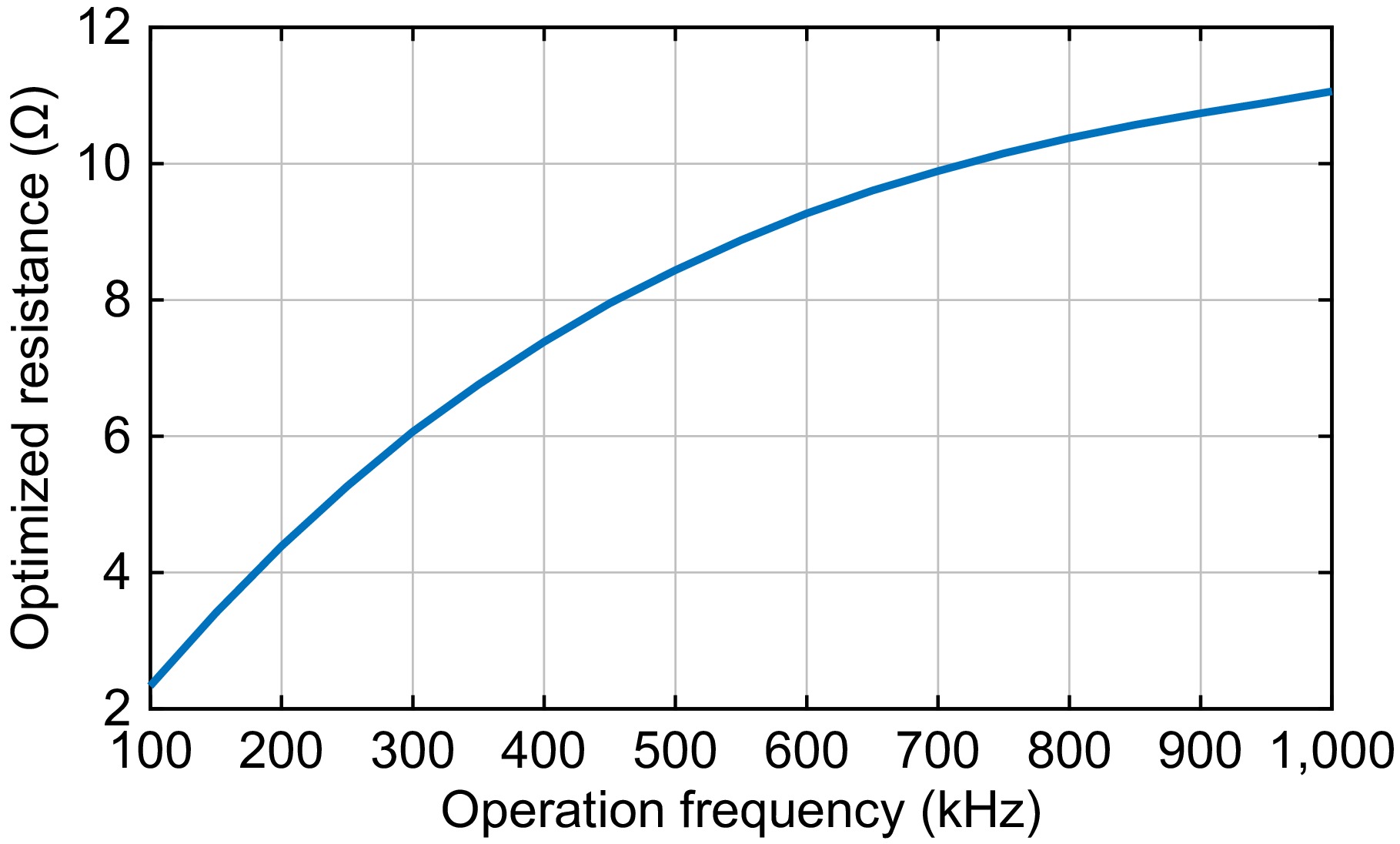
Figure 2.
Optimized rectifier input resistance vs. operation frequency without considering the rectifier loss.
Efficiency optimization considering loss in the rectifier
-
Typically, the electromagnetic valve rating voltage is 2.5 to 5 V feeding by the rectifier. The forward voltage of the low loss rectifier, typically 0.2 to 1 V, is almost the same level as the rectifier output voltage. Hence, the rectifier input resistance optimization should consider the loss in the rectifier. If a power P is required by the electromagnetic valve with a load resistance of Rinput_opt seen from the input side of the rectifier, the rectifier equivalent parasitic resistance can be approximately expressed by:
$ {r_{3\_plus}} = \dfrac{{{V_{forward}}}}{{\sqrt {\dfrac{P}{{{R_{input\_opt\_ex}}}}} }} $ (19) The optimized load resistance Rinput_opt depicted in Eqn (17) couldn’t be used directly for the evaluation of Eqn (19) as (17) is calculated without considering the loss in the rectifier. Practically, the optimized input resistance Rinput_opt_ex is higher than that of (17) as the practical equivalent series resistance should be the sum of r3 and r3_plus, namely,
$ {R_{input\_opt\_ex}} = \omega {k_{12}}{M_{23}}\sqrt {\dfrac{{{L_1}\left( {{r_3} + {r_{3\_plus}}} \right)}}{{{L_1}{r_2}k_{12}^2 + {L_{r2}}{r_1}}}} $ (20) Take a typical forward voltage Vforward = 0.35 V, the rating power P = 0.6 W, together with the optimized rectifier input resistance in Fig. 2, the equivalent rectifier parasitic resistances can be obtained. Replacing r3 with the sum of r3 and r3_plus into Eqn (17) yields the optimized rectifier input resistance Rinput_opt_ex considering loss in the rectifier. Integration of Eqn (19) and (20) yield a unary quadratic, but the general solution is complex. Hence, a simple iterative method is proposed to find the approximate solution as follows.
If the error between Rinput_opt_ex and Rinput_opt is small enough, replacing Rinput_opt_ex with Rinput_opt in Eqn (17) to evaluate r3_plus Eqn (19) is acceptable. With the latest r3_plus, a new Rinput_opt_ex can be obtained based on Eqn (20) again. If the error between the latest Rinput_opt_ex and the previous one are still high, r3_plus must be recalculated according to Eqn (19) with the latest Rinput_opt_ex. Through the iterative method described above, the final rectifier parasitic resistance and the optimized rectifier input resistance can be obtained under a given error threshold. Under an error threshold of 0.01 Ω, the final rectifier parasitic resistance r3_plus is calculated and listed in the right column of Table 1. Figure 3 plots the optimized rectifier input resistance, and Fig. 4 depicts the possible maximum efficiency. Note that the losses in the inverter are not considered for simplification. Considering the main issue is to release the heat power in the human body, ignoring this is reasonable.
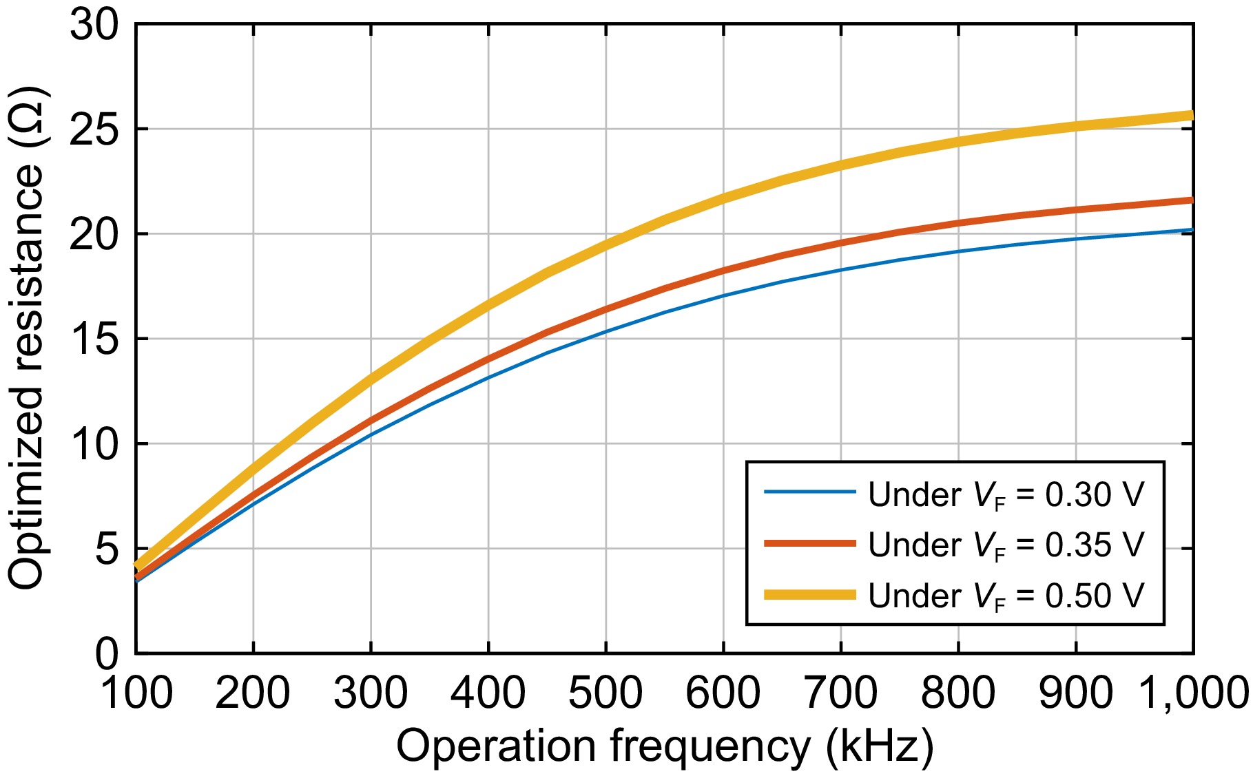
Figure 3.
Optimized rectifier resistance vs. operation frequency considering the rectifier loss.
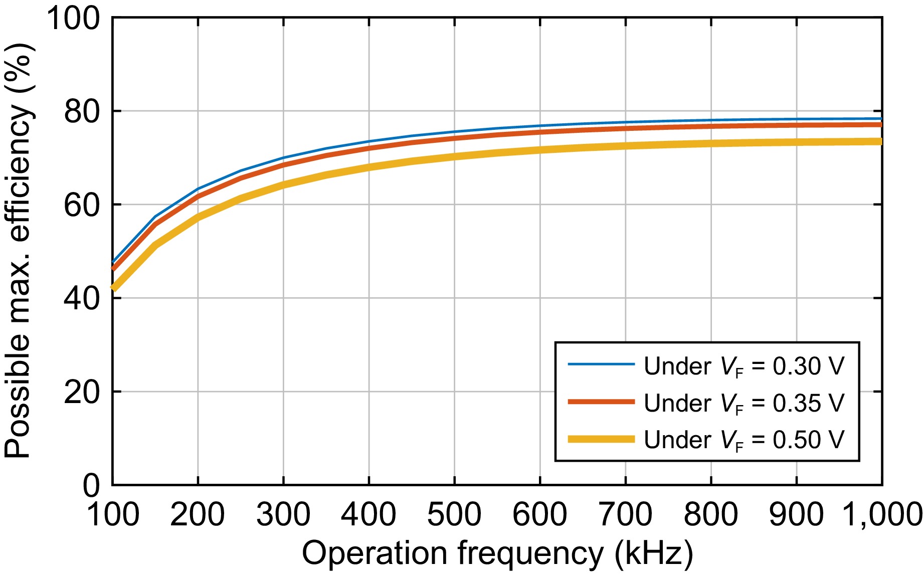
Figure 4.
Possible maximum efficiency vs. operation frequency.
It can be seen from Fig. 3 that the optimized rectifier input resistance is increased with the frequency and the change is large. Take the 0.3 V for example, the range is from 3.4 to 20.2 Ω. Additionally, a higher rectifier forward voltage leads to a higher optimized rectifier input resistance. For example, the optimized input resistance is from 4.1 to 25.7 Ω for a rectifier forward voltage of 0.5 V.
For possible maximum efficiency, it raises with the frequency as shown in Fig. 4. During the range of 100 to 300 kHz, the efficiency increases sharply, while the rising trend becomes slow and shows a saturation after 600 kHz. A lower rectifier forward voltage contributes to a higher efficiency. For example, an approximately 5% efficiency raise is obtained when a rectifier with 0.3 V forward voltage is employed to replace that of 0.5 V.
To provide an insight analysis, losses in typical components are depicted in Fig. 5. Note that the losses depicted by the red line in resonant inductor L1 are almost the same under various rectifier forward voltages, hence the plots with red are overlapped, and the same with L2. One can see that losses decrease with the frequency for all components. At the low-frequency band below 200 kHz, the losses in the resonant inductors of L1 and L2 compose the main parts. At the frequency band higher than 200 kHz, however, the rectifier loss accounts for the biggest components. Additionally, a rectifier with lower forward voltages leads to a lower loss component for all frequencies. Hence, one should select a rectifier with lower forward voltage for this application case to obtain the higher efficiency.
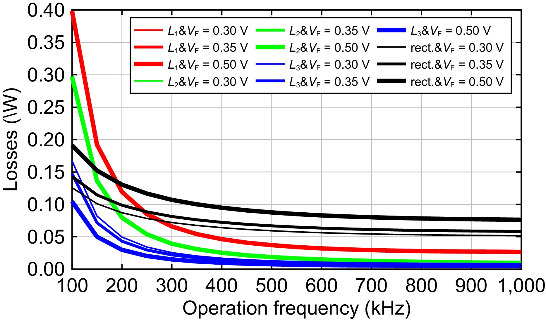
Figure 5.
Losses in main passive components vs. operation frequency.
-
Figure 6 shows the component diagram of the WPT prototype for optimized load resistance. A ruler with a cm units is placed to give a dimension reference. A plastic tube with an 8 mm inner diameter and 10 mm outer diameter, is employed to represent the urethra. For the experiments, the receiving coil is wound around the outside of a hollow tube, then is embedded into the plastic tube representing the urethra. To give a clearer perspective regarding the dimension of the receiving coil, it is layed outside the virtual urethra in Fig. 6. The second relay coil is wound outside the plastic tube and is along the same central axis of the receiving solenoid coil to obtain a high mutual inductance, namely, 3.58 uH for the prototype. The sending coil is placed face-to-face with the first relay coil in the experiments. The gap between the sending coil and the first relay coil is 4 mm, representing the human skin which separates these two coils. The mutual inductance is 2.46 uH. A small PCB board is designed as shown in Fig. 6 to solder the resonant capacitors flexibly for various compensated capacitance. For practical application in the human body, the parallel capacitors are soldered directly to the PCB board which is not appliable for small space requirements.
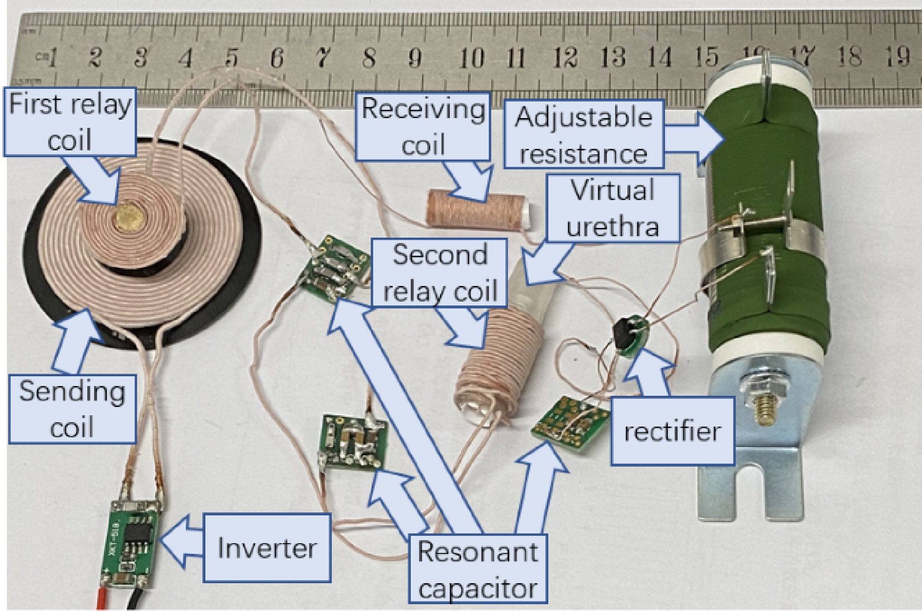
Figure 6.
WPT prototype for optimization experiments.
An XKT 518 inverter module is employed to power the sending coil. For the receiving side, a rectifier CDBHD140L-G is employed to convert the AC current to DC. The rectifier's forward voltage is 0.3, 0.35, and 0.4 V at currents of 200, 600, and 700 mA, which means parasitic resistances of 1.5, 0.58, and 0.57 Ω, respectively. Taking a constant value of 0.35 V as the forward voltage is acceptable for the rectifier parasitic calculation as shown in Eqn (19).
All compensated capacitors are NPO material to obtain small volumes and low-temperature coefficients. The capacitances are designed according to Eqns (2) and (3) while the inductances have been determined as described above. Seven sets of compensated capacitances for corresponding operating frequencies are obtained with connecting different capacitors in parallel. The available capacitors to make the preferred capacitances are 22, 10, 4.7, 3.3, 2 and 1 nF, 330 and 220 pF, respectively.
Performance optimization experiments
-
To verify the optimized rectifier input resistances and efficiency, the electromagnetic in Fig. 6a is replaced by an adjustable resistance. Ten groups of experiments were designed where each is corresponding to an operating frequency, namely, from 100 kHz to 1 MH with an interval of 100 kHz, respectively. For each frequency, the corresponding compensated capacitors are configured on the capacitor PCB boards as calculated according to Eqns (2) and (3) under constant inductances. The output power of the rectifier is measured with a power analyzer of PA1000. For a fair comparison, the voltage of the DC source is adjusted to obtain the same rectifier output power of 0.6 W. Then the experiments under each frequency are conducted.
Taking the frequency of 100 kHz as an example, the following procedures were carried out:
(a) Configure the adjustable resistance powered by the rectifier according to 1.25 times of the optimized rectifier input resistance as shown in Fig. 3 under 100 kHz and VF = 0.35 V, namely, 4.48 Ω.
(b) Adjust the output voltage of the DC source while measuring the power of the load resistance to 0.6 W. The experimental waveforms are captured by an oscillator scope Tektronix DPO 2004B and are shown in Fig. 7a, where scope channels 1, 2, and 3 are for the inverter output voltage, the voltage and current across the adjustable resistance, respectively. Note that the output current is very small and almost cannot be displayed in the scope. Hence, the output voltage, current, and power are measured with the power analyzer PA1000 as shown in Fig. 7b.
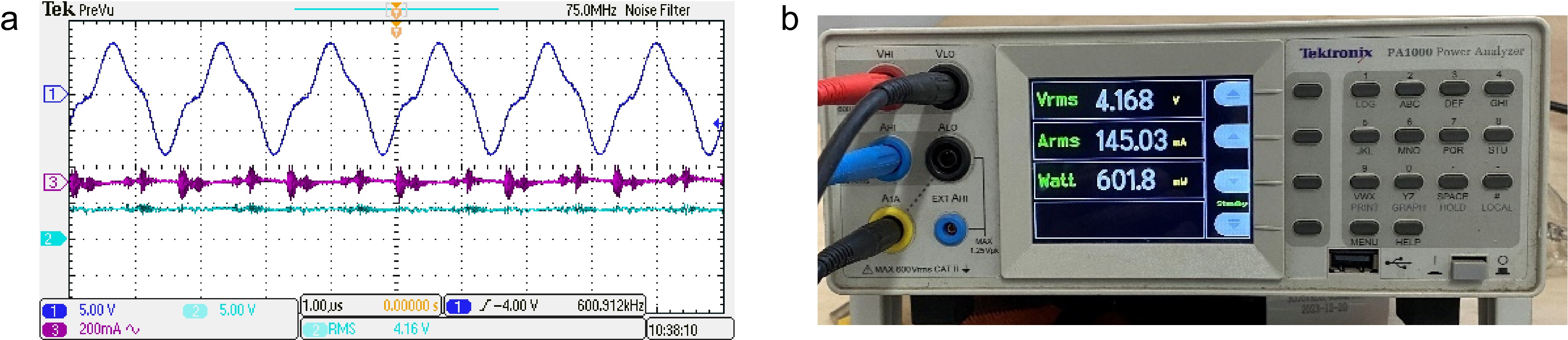
Figure 7.
Experimental waveforms under 600 kHz operation frequency and 27 Ω load resistance. (a) Experimental waveforms, (b) measured output voltage, current, and power.
(c) Record the output voltage and current of the DC source.
(d) Calculate the efficiency with the output power divided by that of the DC source output.
(e) Conduct the steps of (a) to (d) with a corresponding load resistance of 9.4, 13.9, 17.5, 20.5, 22.8, 24.4, 25.6, 26.4, and 27.0 Ω, respectively.
Because experiments are conducted under 10 operating frequencies with each 10 rectifier load resistances, there are 100 efficiency points overall. The efficiency for each specific load resistance is plotted in Fig. 8. Additionally, the predicted possible maximum efficiency under a rectifier 0.35 V and output power 0.6 W is also drawn for comparison.
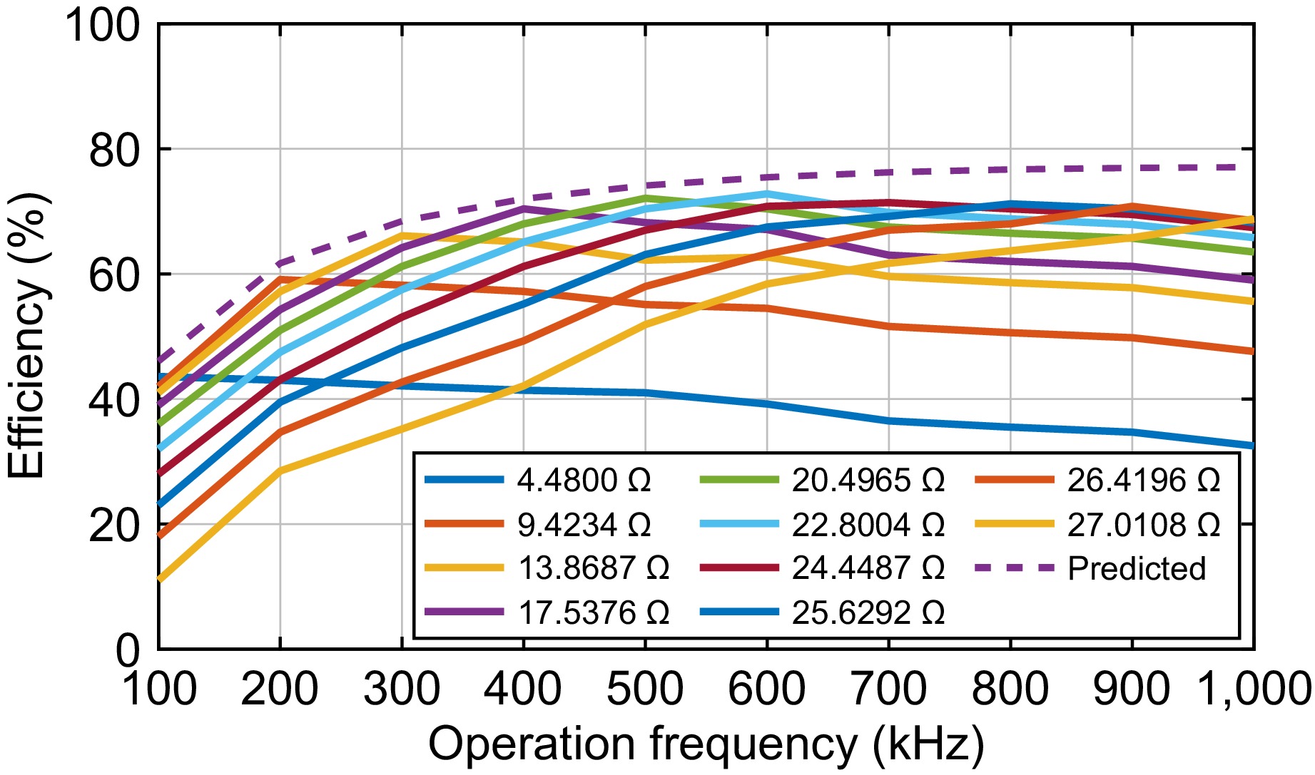
Figure 8.
Measured efficiency vs. operation frequency.
Some conclusions can be drawn from Fig. 8:
(a) The measured maximum efficiencies increase with the frequency to 600 kHz, which agrees with predicted values as shown in Fig. 4. The maximum efficiency is 72.8% under the load resistance of 22.8 Ω and frequency of 600 kHz.
(b) A slight efficiency decrease after 600 kHz was seen. The decrease can be attributed to the increasing switching loss of the inverter with the frequency. Hence, 400 to 700 kHz is a proper frequency range for high efficiency. Correspondingly, the optimized electromagnetic valve resistances can be selected as 15.8, 18.4, 22.8, and 21.9 Ω for frequencies of 400, 500, 600, and 700 kHz, respectively.
(c) The measured maximum efficiencies are lower than the corresponding predicted ones under all frequencies. This is because the losses in some passive components, such as Lr2, Cr1, Cr2, C1, C2, and C3, are not accounted for. The errors for maximum efficiencies, however, are below 5% for all frequencies.
Artificial catheterization experiment
-
An artificial urination experiment with the electromagnetic valve was conducted to verify the performance of the artificial catheterization based on WPT. Figure 9 shows a prototype dedicated for artificial catheterization following the schematic of Fig. 1. An organic glass bracket is employed to support an inverted open bottle representing the bladder. An electromagnetic valve with a 3.5 V rating voltage is employed. Its load resistance is 20.4 Ω which is close to the optimized value under 500 kHz as shown in Fig. 8. For the practical application in humans, the PCB board is not appliable for the small space requirement. Hence, compensated capacitors are soldered directly without PCBs. To prevent electrical leakage, all coils and components in water have been coated with waterproof paint.
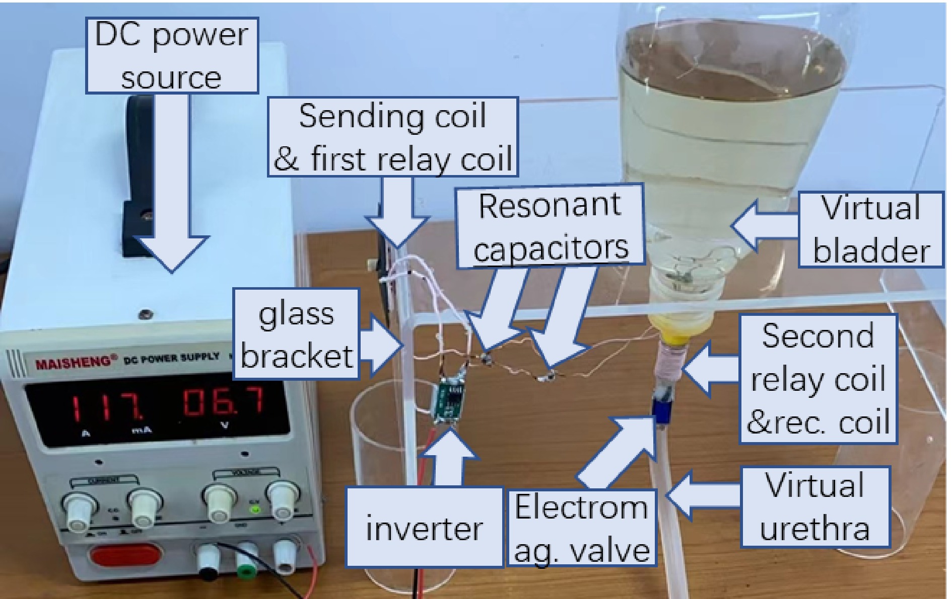
Figure 9.
WPT prototype for artificial catheterization.
Before starting the experiment, 300 ml Chinese tea water was filled into the inverted open bottle, namely, the virtual bladder. Then the DC source voltage was adjusted by hand to power the electromagnetic valve wirelessly. When the DC source voltage reached 6.7 V, the electromagnetic valve was turned on and the water discharged. After 30 s, all the water was completely discharged, which means the artificial catheterization based on the proposed WPT is acceptable.
-
To wirelessly power artificial catheterization with a high efficiency, a WPT with P-LLC-S compensated topology was designed. A wired relay based on LLC compensated topology was designed to relay transfer power from a planar coil to a solenoid coil embedded in the urethra. Coil structures are designed deliberately considering the space dimension restrictions. The optimized load resistance was designed for the highest efficiency. Some major conclusions of this paper are as follows:
(a) The designed artificial catheterization can discharge 300 ml water within 30 s, which meets the common requirement of micturition.
(b) Under the given coils wound with Litz wires, the efficiency increases with the system operation frequency, but the increase shows a saturation trend after 600 kHz. Considering the inverter loss raising with the frequency, 400 to 600 kHz is a proper frequency band for the highest efficiency.
(c) The optimized load resistance for the highest efficiency rises with system operation frequency.
(d) A low rectifier forward voltage is the key factor to improve the system efficiency under any operation frequencies. Additionally, lower rectifier forward voltages yield lower optimized load resistances.
(e) The predicted optimized load resistances are lower than the practical ones because of ignoring losses in some passive components.
-
The authors confirm contribution to the paper as follows: study conception and design: Hu W; data collection: Deng H, Hu W, Li Z; analysis and interpretation of results: Li S; draft manuscript preparation: Li S, Deng H, Zhang Y; manuscript review and editing: Li Z, Hu W. All authors have read and agreed to the published version of the manuscript.
-
All data included in this study are available upon request from the corresponding author.
This research was funded by the National Natural Science Foundation of China (Grant No. 51977151).
-
The authors declare that they have no conflict of interest.
- Copyright: © 2024 by the author(s). Published by Maximum Academic Press, Fayetteville, GA. This article is an open access article distributed under Creative Commons Attribution License (CC BY 4.0), visit https://creativecommons.org/licenses/by/4.0/.
-
About this article
Cite this article
Li Z, Li S, Deng H, Zhang Y, Hu W. 2024. A wireless power transfer based on P-LCC-S compensated topology for artificial catheterization. Wireless Power Transfer 11: e005 doi: 10.48130/wpt-0024-0007 

A wireless power transfer based on P-LCC-S compensated topology for artificial catheterization
- Received: 30 June 2024
- Revised: 22 August 2024
- Accepted: 27 August 2024
- Published online: 23 September 2024
Abstract: A wireless power transfer (WPT) based on P-LCC-S compensated topologic is proposed for artificial catheterization. The proposed method supplies the electromagnetic valve embedded in the urinary tract to control micturition, which cancels the traditional plastic catheter leading out of the body. As a result, the possible inflammation via the plastic catheter is avoided. Three separated modules, namely, the sending module, the relay module, and the receiving module, constitute the WPT. The compensated topologies of the three modules are parallel, LCC, and series, respectively. Considering the relatively large distance and different types for the sending coil and the receiving coil, a wired relay with LCC compensated topology is employed instead of the commonly used domino wireless relay. The performances of the WPT are analyzed and the equivalent load resistance of the electromagnetic valve is optimized and oriented for maximum transfer efficiency. With the proposed WPT, no incisions/holes in the patient's skin or urethral wall are needed to supply the solenoid valve. The measured maximum efficiency is 72.8% under a load resistance of 22.8 Ω and an operation frequency of 600 kHz. A WPT prototype is constructed and the catheterization experiment is conducted where 300 ml water is discharged within 30 s, which meets the common requirements.
-
Key words:
- Wireless power transfer /
- Relay /
- P-LCC-S compensation /
- Artificial catheterization