-
Wireless Power Transfer (WPT) has garnered widespread attention due to its convenience and novelty, significantly enhancing energy transmission efficiency and increasing the product value of next-generation electronic devices and applications. Consequently, numerous issues related to WPT are currently under investigation, with electromagnetic shielding emerging as a critical topic[1]. Unlike traditional power transmission systems, WPT systems are particularly susceptible to electromagnetic interference from the environment due to their reliance on electromagnetic fields for energy transfer. Additionally, it is noteworthy that WPT systems can generate magnetic fields that may disrupt the operation of nearby electronic devices and potentially affect the health of surrounding living organisms[2,3].
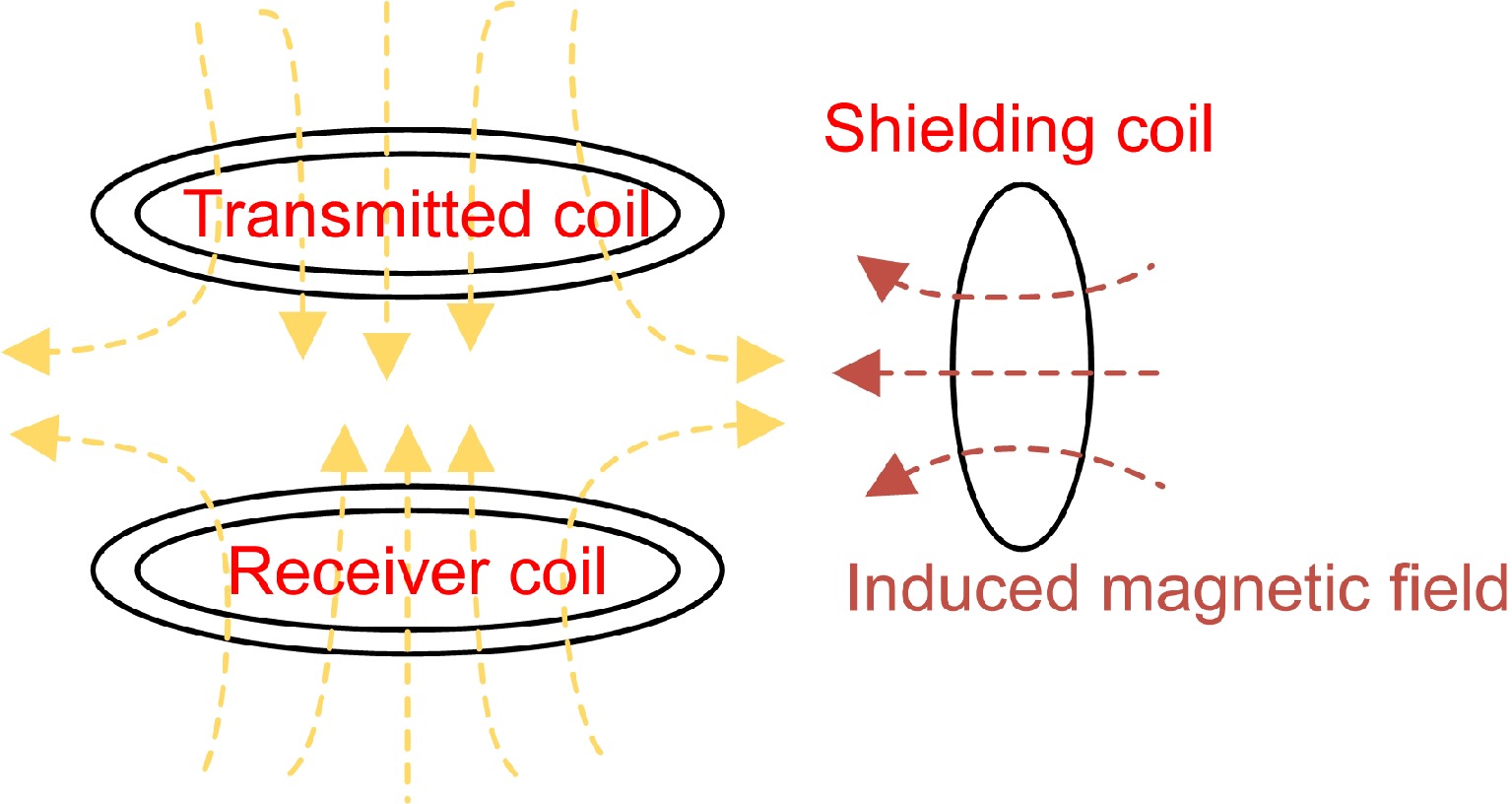
To meet international standards for WPT systems and ensure personal safety, various shielding methods have been proposed to address these electromagnetic issues[4,5]. Passive shielding technology refers to the suppression of electromagnetic radiation using metal shielding materials to block the high-frequency alternating magnetic field generated by the coupling coils. This technology is the most used method for suppressing electromagnetic radiation in WPT systems. Passive shielding technology includes metal shielding[6] and magnetic material shielding[7]. In metal shielding, eddy currents generate an opposing magnetic field to counteract the stray magnetic field. Magnetic material shielding employs ferromagnetic materials to enhance the coupling coefficient between coils and provide a high-permeability channel, thereby reducing stray magnetic fields. However, for WPT systems, both methods have their respective drawbacks. The former affects the mutual inductance between the transmission coils[8], and the high conductivity of the metal plate generates eddy current losses, leading to a sharp decline in transmission efficiency[9], especially when the metal plate is placed close to the transmission coils. Although adding ferromagnetic materials can improve system efficiency and direct most of the magnetic leakage flux, the compensation capacitors or the system's operating frequency may need to be readjusted[10]. In contrast, passive coil shielding, also known as reactive power shielding, is more suitable for high-frequency WPT systems[11] (Fig. 1). Passive coil shielding uses induced currents to generate an opposing magnetic field, counteracting the stray magnetic field[12,13].
Lin et al.[4] utilized a novel W-I coupler design to electromagnetically shield the IPT system operating at 85 kHz, significantly reducing the leakage magnetic field density around the system. Meng et al.[5] employed single-sided and double-sided ferrite shielding methods, achieving maximum reductions of 41.4% and 60.5% in the target area. Pavelek et al.[13] introduced a planar reactive shield with coils and capacitors, significantly reducing the EMI level by −25.48 dB in a 6.78 MHz WPT system without compromising space or power transmission efficiency. Yan et al.[14] developed a finite element model of a wireless energy transfer system with a reconfigurable shielding plate to assess the effect of shielding on the transmission characteristics of the WPT system and thereby identify the optimal operating point and area. Hsu et al.[15] proposed three active electromotive force elimination methods—ISEC, 3DEC, and LFEC—that are highly effective in eliminating stray electromagnetic fields.
Nonetheless, adding shielding coils to the system can affect its electrical characteristics, thereby impacting the efficiency and stability of energy transmission. Therefore, the appropriate design of coil parameters is crucial to suppress electromagnetic interference and ensure stable energy transmission. Given the varying frequency requirements of different WPT systems, researching shielding coils that can easily switch between operating frequencies is essential[16]. This adaptability enhances the versatility of WPT systems, enabling efficient operation across various conditions while minimizing electromagnetic interference. Such research could result in more robust and flexible shielding solutions that cater to the diverse needs of modern WPT applications.
The AirFuel standard stipulates the use of frequencies within the Industrial, Scientific, and Medical (ISM) bands, specifically at 6.78 and 13.56 MHz[17,18]. This standard is now widely applied in consumer electronics, including Samsung smartphones, Dell laptops, and Philips wireless charging toothbrushes. Within this frequency range, PCB coils are highly favored by scholars and enterprises due to their compact size, low cost, and high manufacturing precision[18]. Concurrently, another market mainstream wireless charging standard, Qi, is widely adopted by many manufacturers, including Apple, Huawei, Sony, and Microsoft. Qi standard specifies a frequency range of 100 to 205 kHz and primarily targets portable mobile phones and related products with low power levels (5~15 W). Numerous scholars are investigating WPT systems and electromagnetic field shielding methods within this frequency band[19,20]. Consequently, this paper proposes a design of a PCB shielding coil with a self-resonant frequency close to 13.56 MHz, compliant with the AirFuel standard. Additionally, the resonance frequency of coils can be adjusted to between 100 and 205 kHz using capacitors to meet the requirements of the Qi standard.
This paper proposes a self-resonant coil based on PCB with a self-resonant frequency of around 13.56 MHz, whose resonance frequency can be adjusted for electromagnetic shielding in WPT systems compliant with Qi standards. The impedance curve of the PCB coil was measured, and experiments were conducted on WPT systems operating at 100 and 200 kHz. These experiments yielded several notable findings. Firstly, at frequencies below 13.56 MHz, the skin depth of copper exceeds half the thickness of one oz copper (35 μm), indicating that the AC resistance of the coil, primarily due to the skin effect, is less than twice DC resistance. Secondly, positioning the shielding coil at specific locations within the system results in minimal impact on transmission efficiency while ensuring effective shielding. Thirdly, by identifying the lumped parameters of the coil through curve fitting, the parallel capacitor can be accurately tuned to adjust the resonance frequency. These results underscore the coil's efficacy in minimizing electromagnetic interference while maintaining optimal system performance across various frequencies.
-
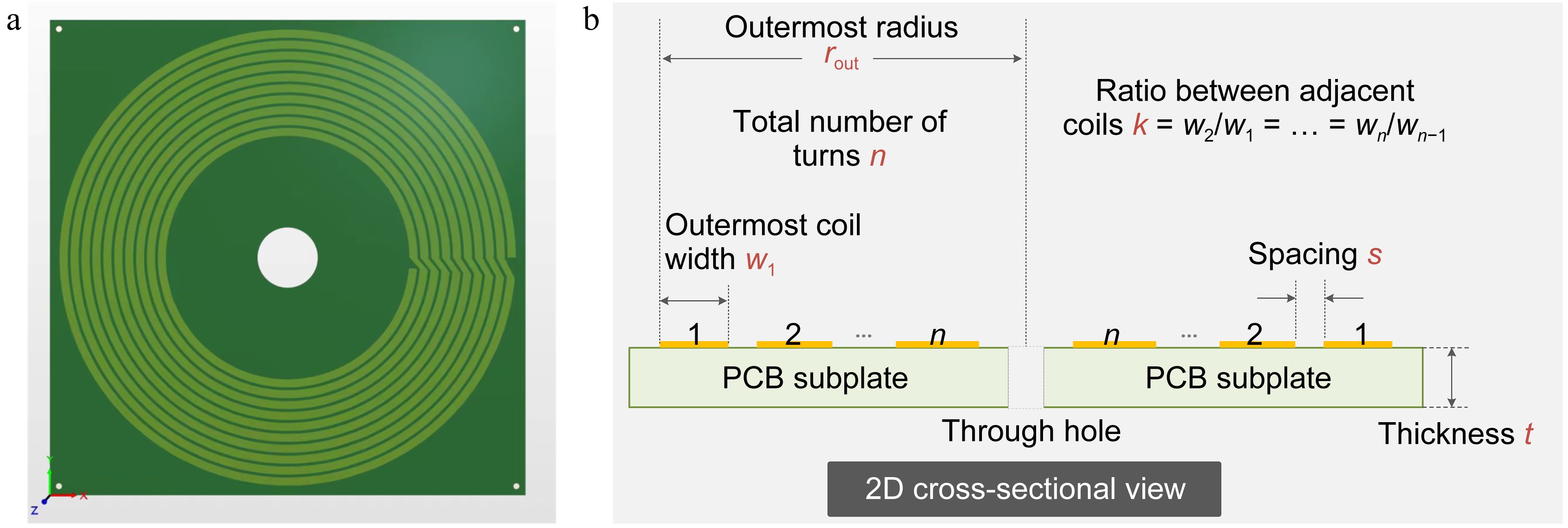
The designed shielding coil is shown in Fig. 2a, with its two-dimensional cross-sectional views presented in Fig. 2b. Five parameters characterize the overall shape of the coil and are utilized to adjust its resonant frequency to 13.56 MHz. The coil is a single-layer PCB coil, featuring holes in the center and at the four corners for fixation purposes. The substrate material of the coil is FR-4, and the substrate has a square shape in the top view. The parameters of the shielding coil are detailed in Table 1.
Table 1. Parameters of the shielding coil.
Parameters Value Number of turns 9 Outermost turn width 3.71 mm Outermost radius 113.54 mm Ratio between adjacent turns 0.999 Ratio of central hole 15 mm Space between adjacent turns 1.75 mm Thickness of copper 0.035 mm Size of PCB subplate 118 mm × 118 mm × 1.6 mm Opening angle of each turn 5° Figure 3 illustrates the equivalent circuit of the coil, comprising an inductor in series with a resistor, parallel to a resonance capacitor, thereby forming a parallel resonance structure. The inductance is determined by copper traces on the PCB, while the resistance characterizes the internal resistance of the copper. The capacitance primarily represents the collective capacitance between turns. Since losses on the shielding coil are negligible, the equivalent circuit can be simplified by omitting the resistor component, resulting in the configuration shown in Fig. 3b. According to the study by Li et al.[21], a third-order circuit is proposed to explain the equivalent circuit of the resonant coil, where both the inter-capacitance (Cs, capacitance between double-layer planar coils) and the intra-capacitance (Cp, turn-turn capacitance of a single-layer planar coil) are considered. Given that the shielding coil proposed is single-layer, the parallel LC configuration is more appropriate than the series LC configuration.
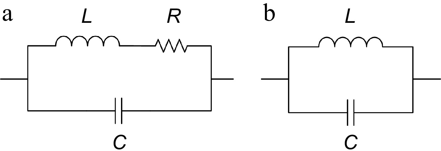
Figure 3.
The equivalent circuit of the shielding coil. (a) Complete equivalent circuit. (b) Simplified equivalent circuit.
From Fig. 3a, the impedance expression for the PCB coil can be derived as:
$ Z\ =\ \dfrac{R}{\omega^2C^2\Bigg[R^2\ +\ \Bigg(\omega L\ -\ \dfrac{1}{\omega C}\Bigg)^2\Bigg]}\ +\ j\dfrac{-\dfrac{R^2}{\omega C}\ -\ \dfrac{\omega L^2}{C}\ +\ \dfrac{L}{\omega C^2}}{R^2\ +\ \Bigg(\omega L\ -\ \dfrac{1}{\omega C}\Bigg)^2} $ (1) where,
$\omega $ $ X\ =\ \dfrac{-\dfrac{R^2}{\omega C}\ -\ \dfrac{\omega L^2}{C}\ +\ \dfrac{L}{\omega C^2}}{R^2\ +\ \Bigg(\omega L\ -\ \dfrac{1}{\omega C}\Bigg)^2} $ (2) Let the imaginary part of the impedance equal to zero to acquire the resonant angular frequency.
$ \omega_0\ =\ \sqrt{\dfrac{L\ -\ R^2C}{CL^2}} $ (3) The skin depth is defined as:
$ \delta\ =\ \sqrt{\dfrac{\rho}{\pi\mu f}} $ (4) where, ρ is the electrical conductivity of copper, f is the frequency, and μ is the absolute permeability of copper. The AC resistance can be expressed as:
$ R_{AC}\ =\ R_{DC}\ \times\ \dfrac{t}{\delta} $ (5) where, t is copper thickness. Calculations show that the skin depth at 13.56 MHz is 17.70 μm, which exceeds half the thickness of 1 oz copper (35 μm). Thus, RAC is less than twice RDC. The AC resistance is approximated as roughly twice the DC resistance and consider it as a constant. Additionally, with inter-turn spacing in the order of millimeters, the proximity effect can be considered negligible in comparison to the skin effect. Consequently, at operating frequencies of 13.56 MHz and below, the AC resistance of the coil can be deemed constant.
According to measurements, the coil's resistance is on the order of milliohms, whereas its inductive reactance near 100 kHz can reach the order of ohms. As the frequency increases, the inductive reactance proportionally increases. Consequently, at frequencies of 100 kHz and above, the resistance R in Fig. 3a can be neglected, leading to a simplified equivalent circuit model as depicted in Fig. 3b. This model simplifies impedance calculations, thereby facilitating subsequent parameter identification.
From the simplified equivalent circuit, the simplified impedance expression for the PCB coil can be derived as:
$ Z\ =\ \dfrac{j\omega L}{1\ -\ \omega^2LC} $ (6) The simplified imaginary part of the impedance can be expressed as:
$ X\ =\ \dfrac{\omega L}{1\ -\ \omega^2LC} $ (7) As shown in Fig. 3, the coil's self-resonance is a parallel resonance, corresponding to parallel compensation. Among the four basic compensation topologies, systems using series-series (SS) compensation and series-parallel (SP) compensation generally exhibit higher efficiency[22]. Due to disadvantages such as high input impedance, computational complexity, and dependence on the coupling coefficient and load, primary side parallel capacitor compensation is seldom used. Compared to SS compensation, SP compensation relies on the coupling factor and requires a larger primary capacitor value to achieve strong magnetic coupling. Consequently, coils with series compensation are most widely used as transmitters and receivers. Therefore, the PCB coil with a self-resonant frequency of 13.56 MHz serves as a shielding coil rather than a transmitter or receiver.
It is generally believed that the inductance of PCB coils does not change significantly (normally less than 10%) with increasing frequency (from zero Hz to around ten MHz). Therefore, the inductance measured at low frequencies is often used as a substitute for the inductance at high frequencies for analysis and calculation. To obtain a more accurate fitting value of the coil inductance at high frequencies compared to measurements at low frequencies, this study explores the use of curve fitting for parameter identification.
Electrical parameter identification
-
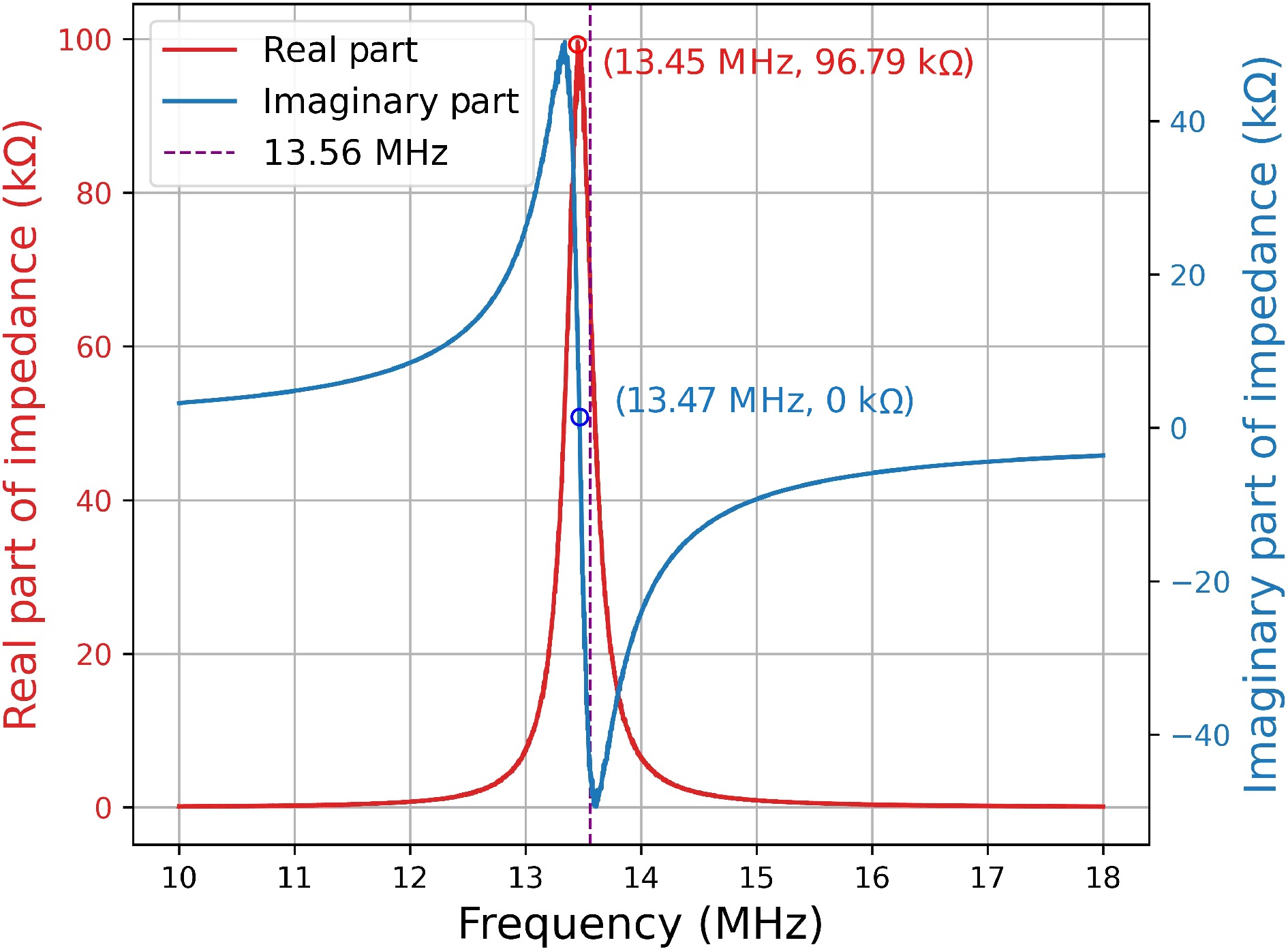
As mentioned in above, the impedance of the PCB coil was measured using an Impedance Analyzer Wayne Kerr 6500B to measure the impedance near the resonance frequency of 13.56 MHz (ranging from 10 to 18 MHz). Curve fitting was performed using the Curve Fitting Toolbox in MATLAB to determine the values of inductance and capacitance.
According to Eqn (3), neglecting the resistance, the fitting equation can be derived as follows:
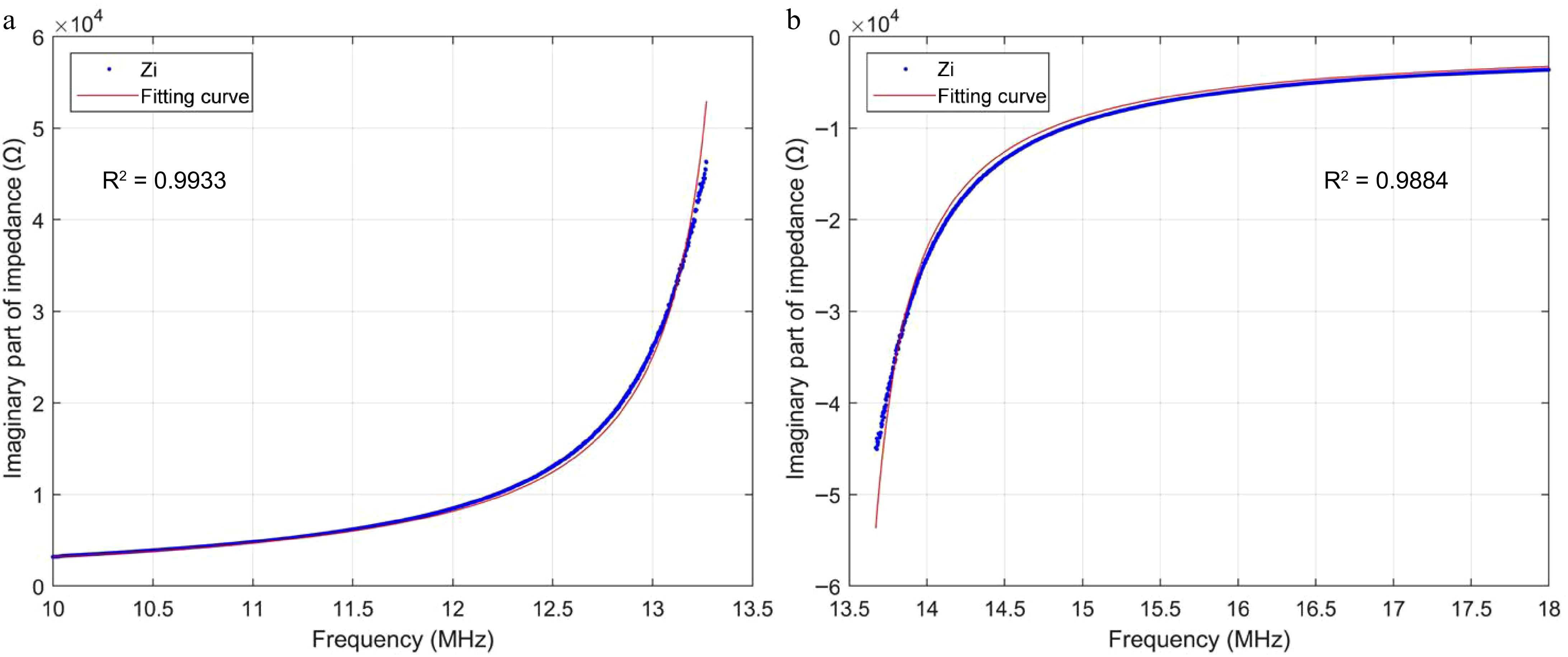
$ X\ =\ \dfrac{2\pi Lf}{1-\dfrac{f^2}{f_0^2}} $ (8) Due to the simplification of the equivalent circuit, an infinite impedance value occurs at the parallel resonance point. Therefore, the imaginary part of the impedance curve in Fig. 4 is divided into two segments on either side of the resonant frequency, and Eqn (8) is used to fit each segment to determine the inductance value. This approach ensures the convergence of the fitting process. During the simplification of the equivalent circuit model, resistance is ignored, resulting in an infinite impedance value at the resonant frequency.
According to Fig. 5 and Eqn (8), the inductance values obtained by fitting are 22.96 and 22.94 μH, respectively. The results are close, and 22.95 μH is taken as the final fitting inductance value. Comparing the fitted inductance values with those measured by the WK6500B shows only a minor discrepancy. Furthermore, adjusting the resonance frequency to specific values like 100 and 200 kHz using a parallel capacitor also verifies the accuracy of the fitted inductance values.
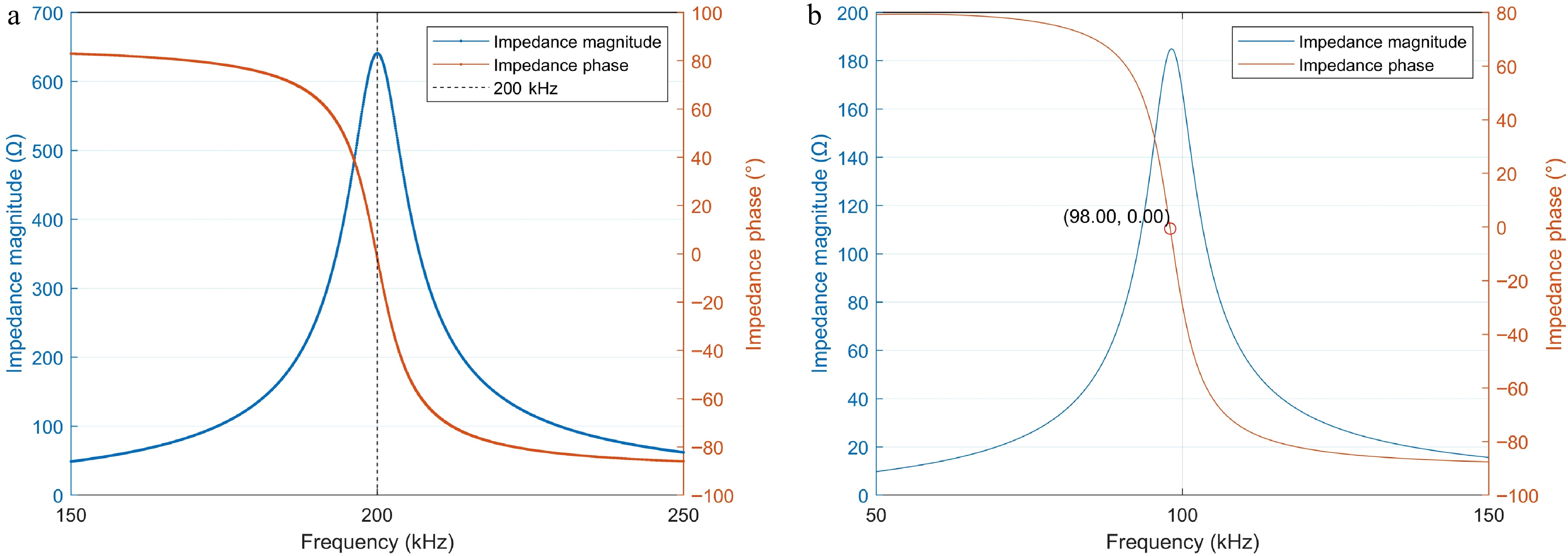
According to the fitting inductance L, the capacitor required to achieve a resonant frequency of 98 and 200 kHz for the shielding coil is 115 and 276 pF, respectively. After connecting the capacitor, the WK6500B was used to measure the impedance curve near 200 and 100 kHz, as shown in Fig. 6.
The final obtained inductance value of the PCB coil remains constant within the operational frequency range. Since the inter-turn capacitance is relatively small, and the resonance frequency is adjusted by adding capacitors in parallel, the capacitance value paralleled is at least three orders of magnitude greater than the coil's inherent capacitance when operating below one MHz. Thus, the inherent capacitance of the coil can be ignored within the WPT system.
Analysis of inductive shield in WPT system
-
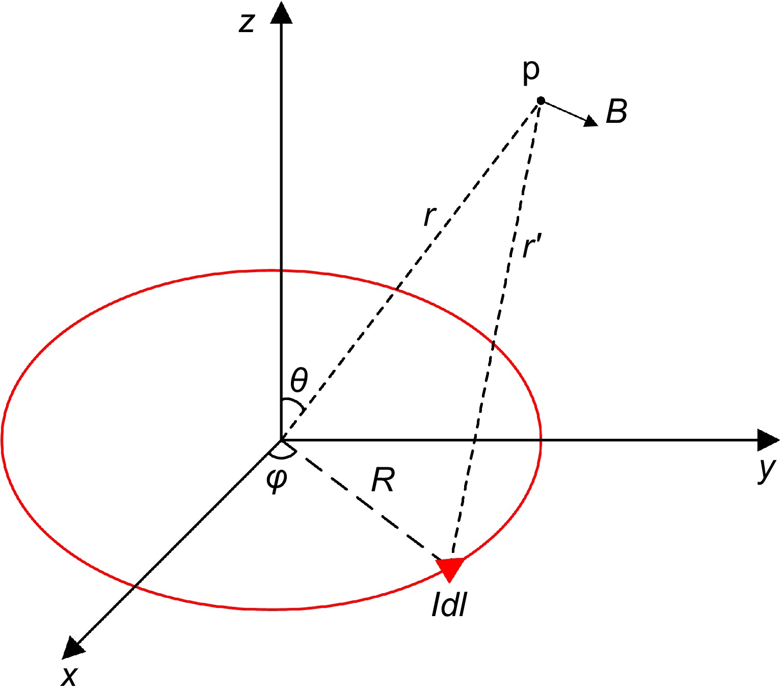
As shown in Fig. 7, r is the displacement vector from the origin to point p, r' is the displacement vector from the current source to point p, R is the displacement vector from the origin to the current source, and l' is a loop of the annular current. According to Biot-Savart law, the magnetic induction intensive B at any point p in space generated by a current element can be expressed as:
$ {\mathbf{B}} = \dfrac{{{\mu _0}I}}{{4\pi }}\int\limits_{l{'}} {\dfrac{{d{\mathbf{l}} \times {\mathbf{r'}}}}{{{{{\mathbf{r'}}}^3}}}} = {k_1}{I_0}{e^{j\omega t}}{{\mathbf{e}}_{\mathbf{B}}} $ (9) where,
$I = {I_0}{e^{j\omega t}}$ According to Faraday's law of electromagnetic induction, when the incident magnetic field generated by the WPT system is applied to the shielding coil, the induced voltage in one turn of the shielding coil vi can be expressed as:
$ {v_i} = - \dfrac{{\partial {\Phi _{Bi}}}}{{\partial t}} = - \dfrac{{\partial \int_{{S_i}} {\mathbf{B}} \cdot d{\mathbf{A}}}}{{\partial t}} $ (10) where,
$ {\Phi _{{Bi}}} $ $ {v_{{sum}}} = \sum\limits_i^n {{v_i}} = - j\omega {I_0}{e^{j\omega t}}\sum\limits_i^n {{k_1}{{\mathbf{e}}_{\mathbf{B}}} \cdot {{\mathbf{S}}_{\mathbf{i}}}} = - j\omega {k_2}{I_0}{e^{j\omega t}} $ (11) where, Si is the oriented area of each turn of the coil, and k2 is a constant coefficient that depends only on the relative position of the shielding coil and the WPT system (ensuring k2 is positive by choosing the direction of Si). It can be observed that the phase of the induced electromotive force generated by the shielding coil differs by 90° from the combined magnetic field generated by the transmitter and receiver. Next, the impact of the shielding coil impedance on the magnetic shielding effect is examined. By controlling the matching capacitors, the resonance frequency of the coil can be changed, thereby determining whether the shielding coil exhibits capacitive or inductive impedance at the operating frequency. The impedance and current of the shielding coil can be expressed as:
$ {Z_{S}} = {R_{S}} + j\left( {\omega {L_{S}} - \dfrac{1}{{\omega {C_{S}}}}} \right) $ (12) $ {i_{S}} = \dfrac{{{v_{{sum}}}}}{{{Z_{S}}}} = \dfrac{{{v_{{sum}}}}}{{{R_{S}} + j\left( {\omega {L_{S}} - \dfrac{1}{{\omega {C_{S}}}}} \right)}} $ (13) At the resonance frequency point, the shielding current can be expressed as:
$ {i_{S}} = \dfrac{{{v_{{sum}}}}}{{{R_{S}}}} $ (14) According to Eqns (9)−(14), the magnetic field generated by the shielding coil can be expressed as:
$ B' = \dfrac{{ - j\omega {{k'}_1}{k_2}{I_0}{e^{j\omega t}}}}{{{R_{S}}}}{{\mathbf{e}}_{{\mathbf{B'}}}} $ (15) where, eB' is related to the position of the shielding coil, but it always forms an acute angle with eB. The magnetic field generated by the shielding coil always lags 90° behind the magnetic field generated by the WPT system.
In the inductive region, the shielding current can be expressed as:
$ {i_{S}} = \dfrac{{{v_{{sum}}}}}{{{R_{S}} + j\omega {L_{S}}}} $ (16) Assuming RS is much less than ωLS, the magnetic field B' generated by the shielding coil can be expressed as:
$ {\mathbf{B}}{' = - }\dfrac{{{{k}_1}{'}{{k}_2}{I_0}{e^{j\omega t}}}}{{{L_{S}}}}{{\mathbf{e}}_{{\mathbf{B'}}}} $ (17) The magnetic field generated by the shielding coil can counteract the magnetic field produced by the WPT system at any point in space.
In the capacitive region, the shielding current can be expressed as:
$ {i_{S}} = \dfrac{{{v_{{sum}}}}}{{{R_{S}} - j\dfrac{1}{{\omega {C_{S}}}}}} $ (18) Assuming RS is much less than 1/(ωCS), the magnetic field B' generated by the shielding coil can be expressed as:
$ {\mathbf{B}}{' = }{{k}_1}{'}{{k}_2}{\omega ^2}{C_{S}}{I_0}{e^{j\omega t}}{{\mathbf{e}}_{{\mathbf{B'}}}} $ (19) The generated magnetic field component is in the same direction as the original magnetic field, thus enhancing the original magnetic field. However, adding the shielding coil will change the mutual inductance between the transmitting and receiving coils, so it cannot be simply assumed that the magnetic field will increase or decrease. To clarify this issue further, the next section will introduce an equivalent circuit model to explain the shielding mechanism when the shielding coil is in the capacitive region.
Analysis of capacitive shield in WPT system
-
Without any external load or power supply, the shielding coil operates as a series resonance in this system, as shown in Fig. 8.
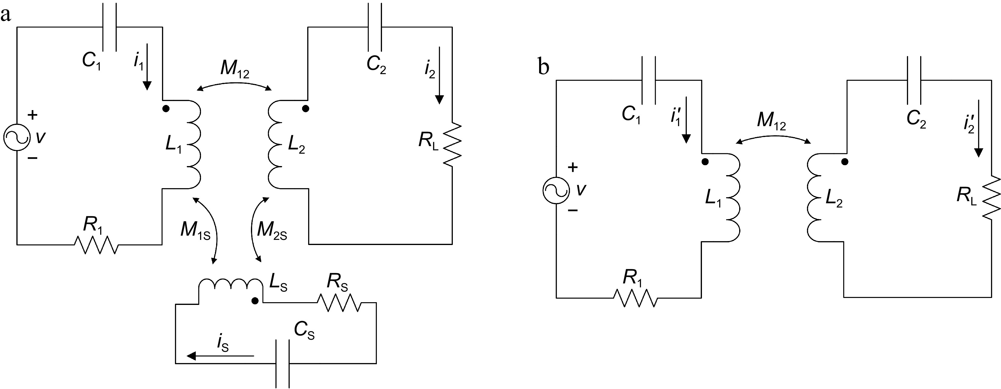
Figure 8.
Circuit structure of the WPT system: (a) with a shielding coil, (b) without a shielding coil.
The equivalent circuit diagram of the WPT system is shown in Fig. 8. As shown in Fig. 8a, L1, L2, and LS are the self-inductance of the source, load, and shielding coil, respectively. C1, C2, and CS are the compensation capacitors accordingly. It is important to note that CS represents an external capacitor, instead of the capacitor C shown in Fig. 3. ω0 is the resonant angular frequency of the system, and it has been defined as Eqn (20) according to Eqn (3). The resonance frequency of the shielding coil is different from the operating frequency of the system ω0.
$ {\omega _0} = 2\pi {f_0}{\text{ = }}\dfrac{1}{{\sqrt {{L_1}{C_1}} }} = \dfrac{1}{{\sqrt {{L_2}{C_2}} }} $ (20) In Fig. 8, R1 and RS are the parasitic resistance of the transmitting coil and shielding coil, respectively. Since the resistance of the load RL (around 10 Ω) is much larger than the parasitic resistance of the receiving coil (less than 10 mΩ), the parasitic resistance of the receiving coil can be neglected, as shown in Fig. 8. M12, M1S, M2S are the mutual inductance of these three coils. v is the output voltage of the inverter. Additionally, i1, i2, and iS are the currents of the coils in the WPT system with a shielding coil, while i1′ and i2′ are the currents of transmitter and receiver coils in the system without a shielding coil.
With the lumped-element circuit shown in Fig. 8a, the WPT system can be expressed in the matrix form according to Kirchhoff voltage law (KVL) as follows:
$ \left[ {\begin{array}{*{20}{c}} v \\ 0 \\ 0 \end{array}} \right] = \left[ {\begin{array}{*{20}{c}} {{Z_1}}&{j{\omega _0}{M_{1{S}}}}&{j{\omega _{.0}}{M_{12}}} \\ {j{\omega _0}{M_{1{S}}}}&{{Z_{S}}}&{j{\omega _0}{M_{2{S}}}} \\ {j{\omega _0}{M_{12}}}&{j{\omega _0}{M_{2{S}}}}&{{Z_2}} \end{array}} \right]\left[ {\begin{array}{*{20}{c}} {{i_1}} \\ {{i_S}} \\ {{i_2}} \end{array}} \right] $ (21) where,
$ Z_i\ =\ R_i\ +\ j\omega_0L_i\ -\ \dfrac{j}{\omega_0C_i} $ (22) where, v is the voltage vector of the equivalent AC input power supply, and Zi (i = 1, 2, or S) represents the impedance of the three coils, respectively. Since the coils are resonant, the imaginary part of Zi should be zero. By Gaussian elimination, Eqn (21) is simplified as:
$ \left[ {\begin{array}{*{20}{c}} {{Z_1} + \dfrac{{{{({\omega _0}{M_{1{S}}})}^2}}}{{{Z_{S}}}}}&{{\text{j}}{\omega _0}\left({M_{12}} - {\text{j}}{\omega _0}\dfrac{{{M_{1{S}}}{M_{2{S}}}}}{{{Z_{S}}}}\right)} \\ {{\text{j}}{\omega _0}\left({M_{12}} - {\text{j}}{\omega _0}\dfrac{{{M_{1{S}}}{M_{2{S}}}}}{{{Z_{S}}}}\right)}&{{Z_2} + \dfrac{{{{({\omega _0}{M_{2{S}}})}^2}}}{{{Z_{S}}}}} \end{array}} \right]\left[ {\begin{array}{*{20}{c}} {{i_1}} \\ {{i_2}} \end{array}} \right] = \left[ {\begin{array}{*{20}{c}} v \\ 0 \end{array}} \right] $ (23) According to Eqn (23), the equivalent mutual inductance between the transmitting coil and receiving coil
${M'_{12}}$ ${Z'_1}$ ${Z'_2}$ $ {M'_{12}} = {M_{12}} - {\text{j}}{\omega _0}\dfrac{{{M_{1{\text{S}}}}{M_{2{\text{S}}}}}}{{{Z_{S}}}} $ (24) $ {Z'_1} = {Z_1} + \dfrac{{{{({\omega _0}{M_{1{S}}})}^2}}}{{{Z_{S}}}} $ (25) $ {Z'_2} = {Z_2} + \dfrac{{{{({\omega _0}{M_{2{\text{S}}}})}^2}}}{{{Z_{\text{s}}}}} $ (26) The equivalent currents of the transmitting coil and the receiving coil in WPT system with a shielding coil can be expressed as:
$ \left\{ {\begin{array}{*{20}{c}} {{i_1} = \dfrac{{v{Z'_2}}}{{{Z'_1}{Z'_2} + {{({\omega _0}{M_{12}}{'})}^2}}}} \\ {{i_2} = \dfrac{{j{\omega _0}v{M'_{12}}}}{{{Z'_1}{Z'_2} + {{({\omega _0}{M'_{12}})}^2}}}} \end{array}} \right. $ (27) The equivalent currents of the transmitting coil and the receiving coil in WPT system without a shielding coil can be expressed as:
$ \left\{ {\begin{array}{*{20}{c}} {{i'_1} = \dfrac{{v{Z_2}}}{{{R_1}{R_{L}} + {{({\omega _0}{M_{12}})}^2}}}} \\ {{i'_2} = \dfrac{{j{\omega _0}v{M_{12}}}}{{{R_1}{R_{L}} + {{({\omega _0}{M_{12}})}^2}}}} \end{array}} \right. $ (28) When the shielding coil impedance is capacitive, it can be represented by an equivalent capacitance.
$ {Z_{S}} = \dfrac{1}{{j{\omega _0}{C_{{eq}}}}} $ (29) Substituting Eqn (29) into Eqns (24)−(26).
$ {M'_{12}} = {M_{12}}\left( {1 + \dfrac{{\omega _0^2{M_{1{S}}}{M_{2{S}}}{C_{{eq}}}}}{{{M_{12}}}}} \right) $ (30) $ {Z'_1} = {Z_1} + j\omega _0^3{C_{{eq}}}M_{1{S}}^2 $ (31) $ {Z'_2} = {Z_2} + j\omega _0^3{C_{{eq}}}M_{{2S}}^2 $ (32) According to Eqns (31) and (32), the equivalent impedance of the transmitting coil and the receiving coil increases. Additionally, the mutual inductance can be expressed in terms of the coupling coefficient (
${k_{ab}} = {M_{ab}}/\sqrt {{L_a}{L_b}} $ $ \left\{ {\begin{array}{*{20}{c}} {{M_{1{S}}} = {k_{1{S}}}\sqrt {\dfrac{{{L_1}}}{{{C_{{\text{eq}}}}}}} } \\ {{M_{12}} = {k_{12}}\sqrt {{L_1}{L_2}} } \\ {{M_{2{S}}} = {k_{2{S}}}\sqrt {\dfrac{{{L_2}}}{{{C_{{\text{eq}}}}}}} } \end{array}} \right. $ (33) where, k1S, k2S, and k12 are the coupling coefficients between the transmitter and the shielding coil, the receiver and the shielding coil, and the transmitter and the receiver, respectively. Therefore, after adding the shielding coil, the system's equivalent mutual inductance and equivalent coupling coefficient can be expressed as:
$ {M'_{12}} = {M_{12}}\left( {1 + \dfrac{{\omega _0^2{k_{1{S}}}{k_{2{S}}}}}{{{k_{12}}}}} \right) $ (34) $ {k'_{12}} = {k_{12}} + \omega _0^2{k_{1{S}}}{k_{2{S}}} $ (35) According to Eqn (35), when the shielding coil impedance is in the capacitive region, the equivalent coupling coefficient between the transmitting coil and the receiving coil in the system with the shielding coil is higher compared to the system without the shielding coil. This enhances the magnetic field between the coils, consistent with the conclusion above.
According to Eqn (29), since the magnitude of the impedance of shielding coil is larger than 10 Ω, it is reasonable to believe that Ceq < ω0 / 10. Assuming RL is much larger than
$ \omega _0^3{C_{{eq}}}M_{2{S}}^2 $ ${Z'_2} = {{Z}_2} = {R_{L}}$ $ i_1\ < \ i'_1 $ ${i_2}$ ${i'_2}$ ${i_2}$ ${i'_2}$ $ \alpha\ =\ \dfrac{i_2}{i'_2}\ =\ \dfrac{M_{12}\beta\ +\ \omega_0^2M_{1S}M_{2S}C_{eq}\beta}{M_{12}\beta\ +\ j\omega_0^3C_{eq}M_{12}M_{1S}^2R_L} $ (36) where,
$ \beta = {R_1}{R_{L}} + \omega _0^2M_{12}^2 $ (37) According to Eqns (36) and (37), the relationship between α and 1 depends on γ:
$ \gamma=\dfrac{\omega_0^2M_{1S}M_{2S}C_{eq}\beta}{\omega_0^3C_{eq}M_{12}M_{1S}^2R_L}=\dfrac{R_1R_L\ +\ \omega_0^2M_{12}^2}{\omega_0M_{1S}R_L} $ (38) According to Eqn (33) and the quality factor of the transmitter Q1 = ω0L1/R1, and assuming LS is close to L1 and L2, γ also can be expressed as:
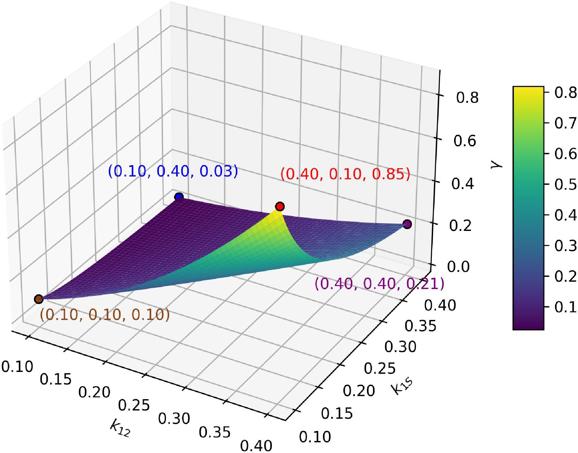
$ \gamma=\dfrac{R_L/Q_1\ +\ \omega_0k_{12}^2L_2}{k_{1S}R_L} $ (39) where, the reference range for the quality factor Q1 of the transmitting coil is 100 to 400, RL is around 10 Ω, the reference range for k12 and k1S is 0.1 to 0.4, L2 is approximately 50 μH. We estimate γ < 1 at the reference magnitude, as shown in Fig. 9. Therefore, α is also less than one at the reference magnitude, which means
${i_2} < {i'_2}$ Parameters Value Load RL 10 Ω Quality factor of transmitter Q1 200 Inductance L2 50 μH Next, the losses in the shielding coil are considered. The shielding coil operates at or very close to its series resonance frequency in the WPT system. Therefore, the losses in the shielding coil can be primarily attributed to the parasitic resistance of shielding coil RS. The losses can be calculated using Joule’s law. According to Fig. 8 and Eqn (21), the current of shielding coil iS and receiver coil i2 can be expressed as:
$ {i_{S}} = \dfrac{{ - ({M_{12}}{M_{2{S}}}\omega _0^2 + j{\omega _0}{M_{1{S}}}{R_2})u}}{k} $ (40) $ {i_2} = \dfrac{{ - (j{\omega _0}{M_{12}}{R_{S}} + {M_{1{S}}}{M_{2{S}}}\omega _0^2)}}{k}u $ (41) where,
$ k = M_{12}^2{R_{S}}\omega _0^2 - 2j\omega _0^3{M_{12}}{M_{1{S}}}{M_{2{S}}} + M_{1{S}}^2{R_2}\omega _0^2 + M_{2{S}}^2{R_1}\omega _0^2 + {R_1}{R_2}{R_{S}} $ (42) The losses in the shielding coil QS and power in receiver coil P can then be represented as:
$ {Q_{S}} = {\left| {{i_{S}}} \right|^2}{R_{S}} $ (43) $ P = {\left| {{i_2}} \right|^2}{R_2} $ (44) Since
$ M_{1{S}}^2{R_2}\omega _0^2 $ $ M_{12}^2{R_{S}}\omega _0^2 + M_{2{S}}^2{R_1}\omega _0^2 + {R_1}{R_2}{R_{S}} $ ${M_{1{S}}}{M_{2{S}}}\omega _0^2$ ${\omega _0}{M_{12}}{R_{S}}$ $ \dfrac{{{Q_{S}}}}{P} = \dfrac{{{{\left| {{i_{S}}} \right|}^2}{R_{S}}}}{{{{\left| {{i_2}} \right|}^2}{R_2}}} = \dfrac{{(M_{12}^2M_{2{S}}^2\omega _0^4 + \omega _0^2M_{1{S}}^2R_2^2){R_{S}}}}{{M_{1{S}}^2M_{2{S}}^2\omega _0^4{R_2}}} $ (45) Through estimates similar to those in Eqn (38) and Eqn (39), we can determine that
$ M_{12}^2M_{2{S}}^2\omega _0^4 + \omega _0^2M_{1{S}}^2R_2^2 $ $ M_{1{S}}^2M_{2{S}}^2\omega _0^4 $ Shielding effect of the shielding coil in resonance
-
When the shielding coil operates in resonance, its impedance can be expressed as ZS = RS. According to Eqns (21)−(28), the ratio of |
$i_2 $ $i'_2 $ $ \left| \alpha \right| = \dfrac{{\left| {{M_{12}} - j{\omega _0}\dfrac{{{M_{1{S}}}{M_{2{S}}}}}{{{R_{S}}}}} \right|\beta }}{{{M_{12}}\left| {\left( {{R_1} + \dfrac{{\omega _0^2M_{1{S}}^2}}{{{R_{S}}}}} \right)\left( {{R_{L}} + \dfrac{{\omega _0^2M_{2{S}}^2}}{{{R_{S}}}}} \right) + \omega _0^2{{\left( {{M_{12}} - j{\omega _0}\dfrac{{{M_{1{S}}}{M_{{2S}}}}}{{{R_{S}}}}} \right)}^2}} \right|}} $ (46) Since
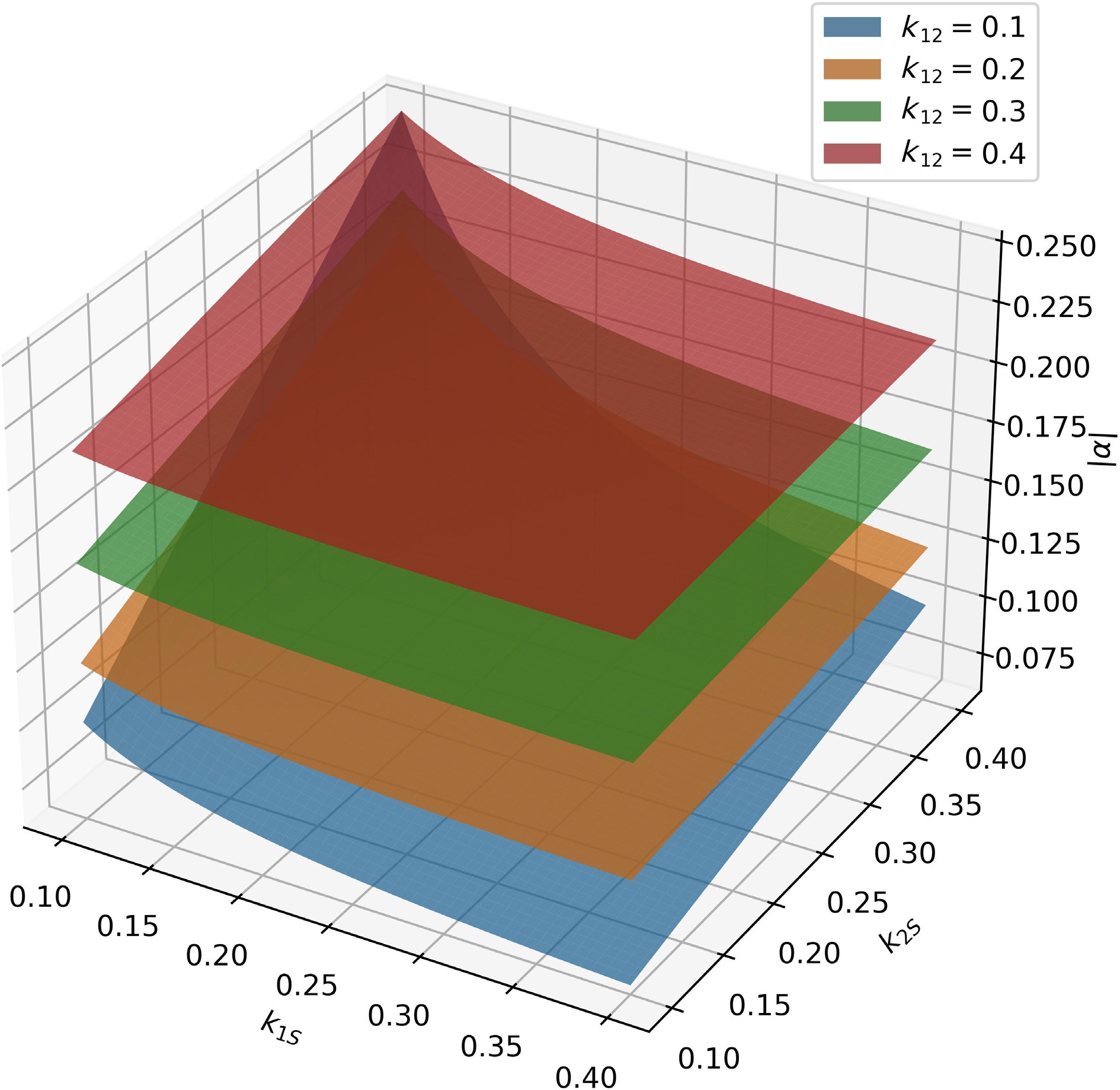
$ \left| {{\omega _0}{M_{1{S}}}{M_{2{S}}}/{R_{S}}} \right| $ $ \left| {{M_{12}}} \right| $ ${R_1}$ $\omega _0^2M_{1{S}}^2/{R_{S}}$ $ \omega _0^2M_{1{S}}^2{R_{L}} $ $ 2\omega _0^3{M_{12}}M_{{1S}}^2M_{2{S}}^2 $ $ {\omega _0}{M_{12}}{M_{1{S}}}{R_{L}} $ $ {\omega _0}M_{12}^3{R_{S}} $ $\left| \alpha \right|$ $ \left| \alpha \right| = \dfrac{{{M_{2{S}}}({R_1}{R_{L}} + \omega _0^2M_{12}^2)}}{{{\omega _0}{M_{12}}{M_{1{S}}}{R_{L}}}} = \dfrac{{\dfrac{{{R_{L}}{k_{2{S}}}}}{{{Q_1}}} + {\omega _0}k_{12}^2{k_{1{S}}}{L_2}}}{{{k_{12}}{k_{1{S}}}{R_{L}}}} $ (47) We estimate the value of
$\left| \alpha \right|$ $\left| \alpha \right|$ -
Finite element electromagnetic field simulations are conducted using Ansys Maxwell software to explore the shielding effect of the shielding coil on the axial magnetic field in both WPT systems with and without the shielding coil.
According to Fig. 11, in the WPT system without the shielding coil, the magnetic flux density at the observation points remains around 80 μT. After adding the shielding coil, the magnetic flux density at the observation points drops significantly below 60 μT in a large portion of the area, and the overall magnetic flux density is reduced. The simulation results preliminarily verify the shielding effect of the shielding coil on the electromagnetic field in the WPT system.
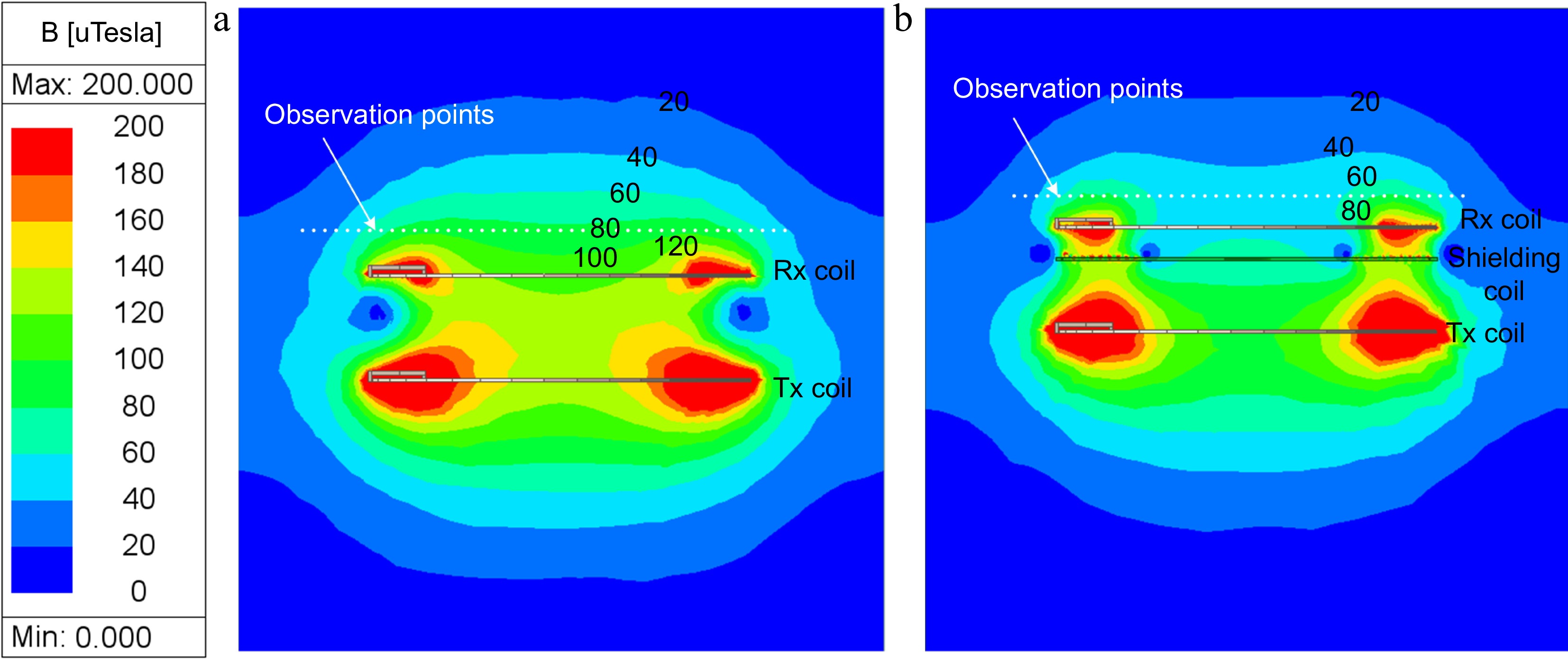
Figure 11.
Distribution of the simulated magnetic field: (a) without, (b) with the resonant reactive shield.
Shielding effect experiment setup
-
Experiments were conducted on two WPT systems operating at different frequencies to explore the effects of the shielding coil on the systems' magnetic field and transmission efficiency. In the first set of experiments (Experiment A), the resonance frequency of transmitter and receiver was set to 100 kHz, while in the second set (Experiment B), it was set to 200 kHz. In Experiment A, the resonance frequency of the shielding coil was set to 98 kHz, which means that it worked in the inductive region. In Experiment B, the resonance frequency of the shielding coil was adjusted to match the resonance frequencies of the WPT system's transmitting and receiving coils.
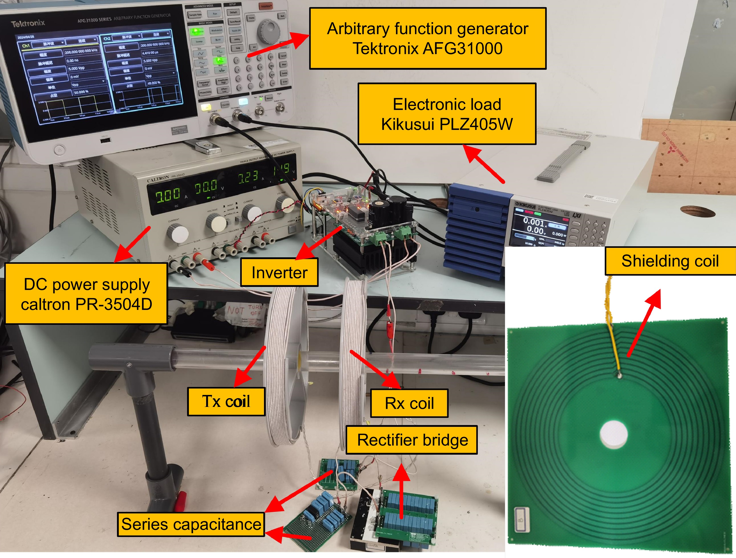
As shown in Fig. 12, the WPT systems used in the experiments consist of transmitting and receiving coils (Tx coil and Rx coil) that utilize series capacitance compensation, while the shielding coil employs parallel capacitance to adjust to the corresponding resonance frequency. The inverter is powered by a DC power supply, and an arbitrary function generator provides the driving waveform (a pulse wave corresponding to the resonant frequency) to the inverter. The alternating current from the receiving coil is connected to the electrical load through a rectifier bridge. The main parameters of the system are shown in Table 3.
Table 3. Parameters for WPT system used in the experiments.
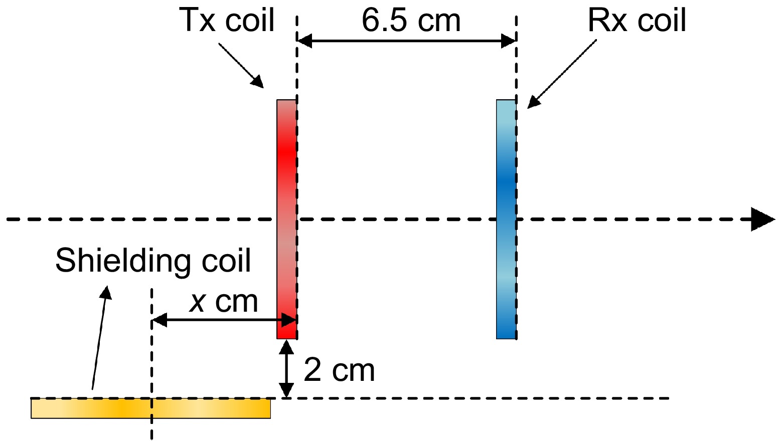
Parameters Value Operation frequency of Experiment A 100 kHz Operation frequency of Experiment A 200 kHz Number of turns of Tx and Rx coils 11 Radius of Tx coil and Rx coil 10 cm Load 10 Ω Inductance of Tx coil 47.52 μH Inductance of Rx coil 47.75 μH Series capacitance of Tx coil in Experiment A 53.30 nF Series capacitance of Rx coil in Experiment A 53.05 nF Series capacitance of Tx coil in Experiment B 13.33 nF Series capacitance of Rx coil in Experiment B 13.26 nF Distance between Tx coil and Rx coil 6.5 cm Mutual induction of Tx coil and Rx coil 9.847 μH Wire diameter of Tx coil and Rx coil 1.8 mm In the experiments, two placement schemes for the shielding coil were tested: one parallel to the transmitting and receiving coils, and the other perpendicular to them. Using the transmitting coil as the coordinate origin, the shielding coil was positioned at various distances from the transmitting coil, and the output power and transmission efficiency of the system were measured.
As shown in Fig. 13, there are eight test placement schemes for shielding coils parallel to the transmitting coil (Cases a to h). Case a serves as a control group without a shielding coil. Additionally, the output power of the receiving coil and the input power of the transmitting coil were measured to calculate the efficiency across the resonator.
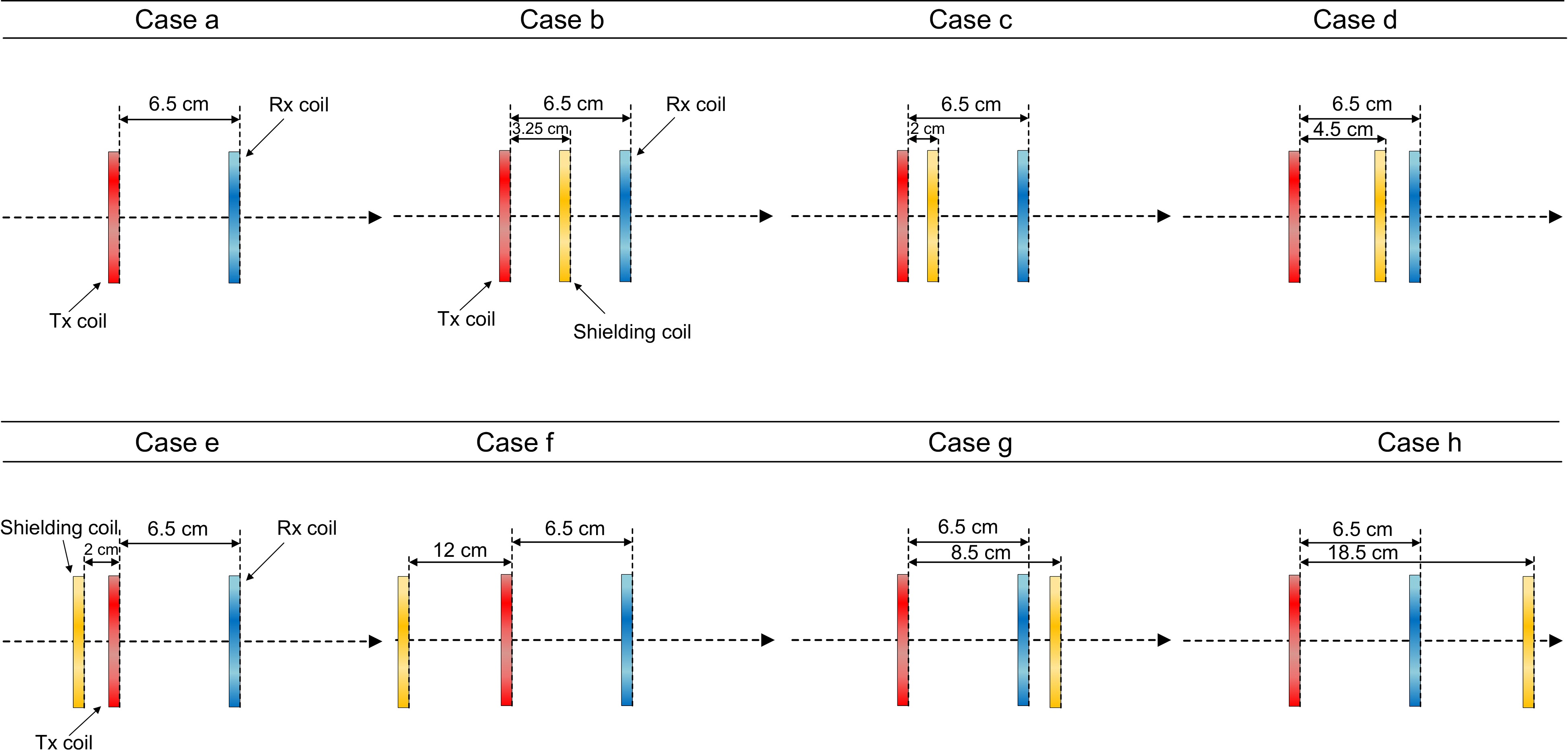
Figure 13.
Schematic diagram of shielding coil placed in different positions (parallel to the transmitting coil).
As shown in Fig. 14, the distance between the center of the shielding coil and the Tx coil is defined as x, ranging from −16 to 14 cm. Additionally, by placing the shielding coil on a straight line perpendicular to the transmitting coil and 2 cm away from it, a set of experimental data was obtained to test the shielding effect on side magnetic leakage.
Results of Experiment A
-
This section focuses on the impact of introducing the shielding coil and placing it in different positions on the transmission efficiency and output power of the system. Figure 15 shows the transmission efficiency at both ends of the transmitting coil and the receiving coil, as well as the output power at the receiving coil, with the horizontal axis representing the power supply voltage. The four curves in the figure can be divided into two groups: one group represents the resonator (the two ends of the resonant coils), and the other group represents the entire WPT system. Analyzing the structure of the entire system reveals that the difference between these two losses mainly arises from the rectifier and inverter.
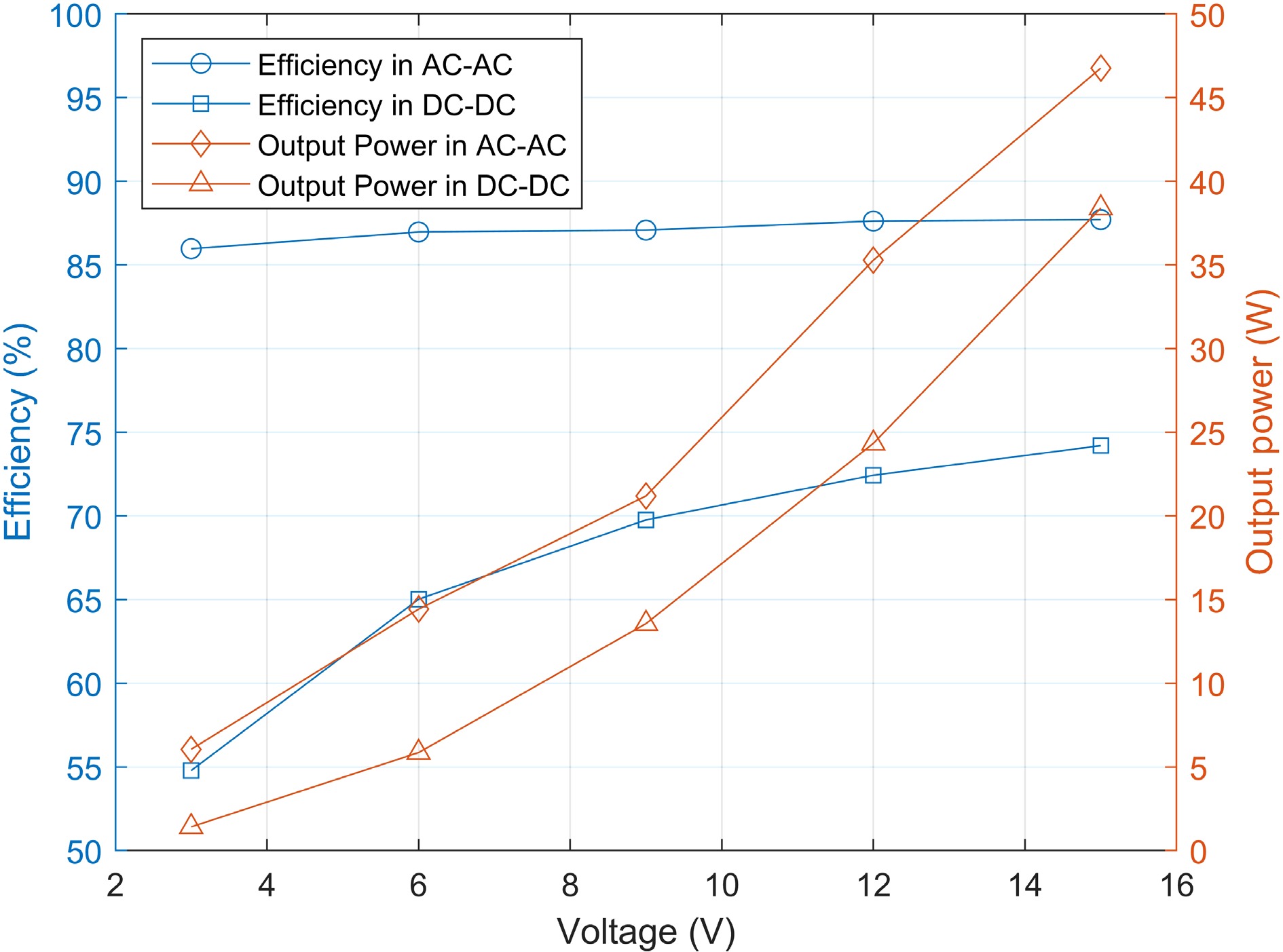
Figure 15.
Efficiency between resonator or WPT system and output power of Rx coil or rectifier bridge in Experiment A.
From Fig. 16, it is evident that placing the shielding coil parallel to the transmitting coil at different positions has varying effects on the system's transmission efficiency and output power. According to previous theoretical analysis, the shielding effect of the coil is evaluated by the amplitude of the secondary current, which is closely related to the output power. Based on Fig. 16, in Case h, the output power does not decrease significantly, and there is a situation where the primary current becomes too large, causing the inverter to fail. Although Cases c and e effectively reduce output power, they also severely impact the system's transmission efficiency. When the shielding coil is placed between the transmitting and receiving coils, two cases—Case b and Case d—are able to effectively reduce output power while minimizing the impact on transmission efficiency. When the shielding coil is placed outside the transmission coils, Case f shows the best overall shielding effect. It is worth noting that the results of Experiment A validate the shielding effect of the shielding coil when its resonant frequency is in the inductive region.

Figure 16.
(a) Efficiencies, and (b) output powers of the WPT system in Experiment A from Case a to h.
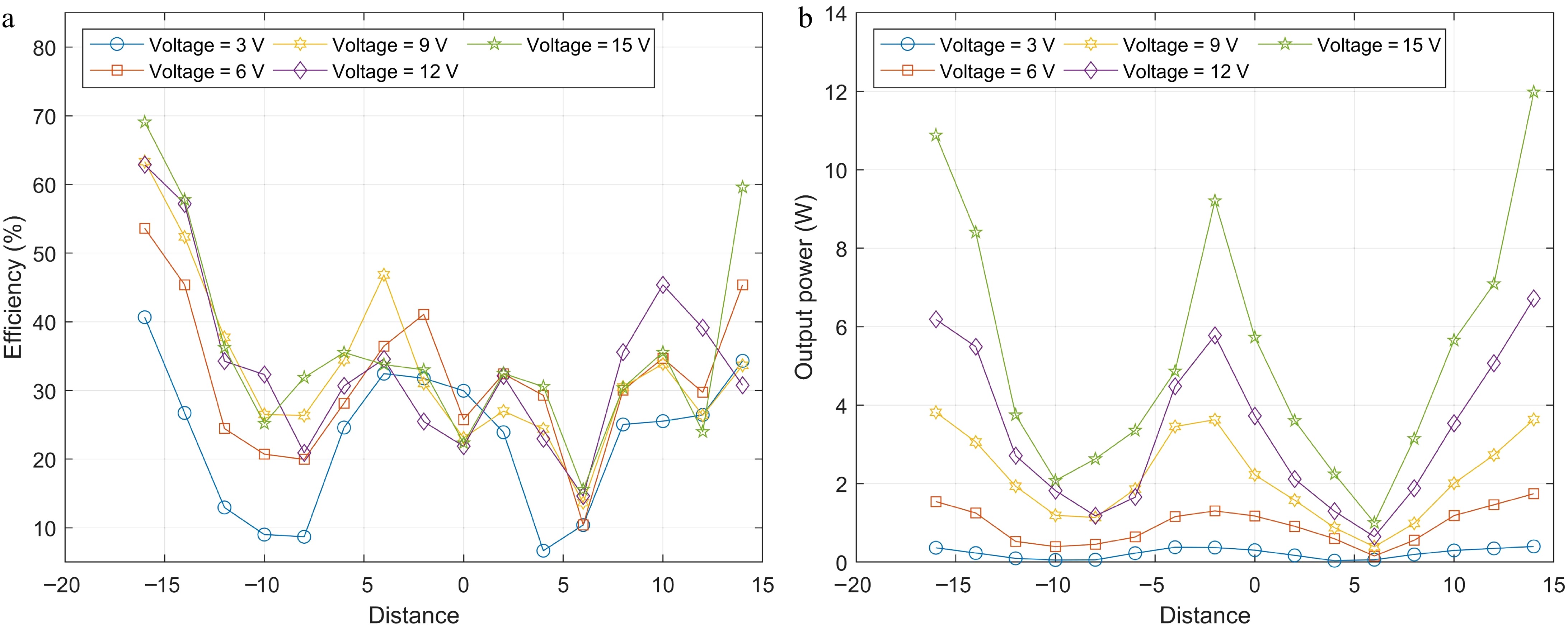
From Fig. 17, it is evident that placing the shielding coil perpendicular to the transmitting coil results in a reduction in both transmission efficiency and output power compared to the system without a shielding coil. However, the extent of this reduction varies depending on the specific placement. These effects can be summarized as follows:
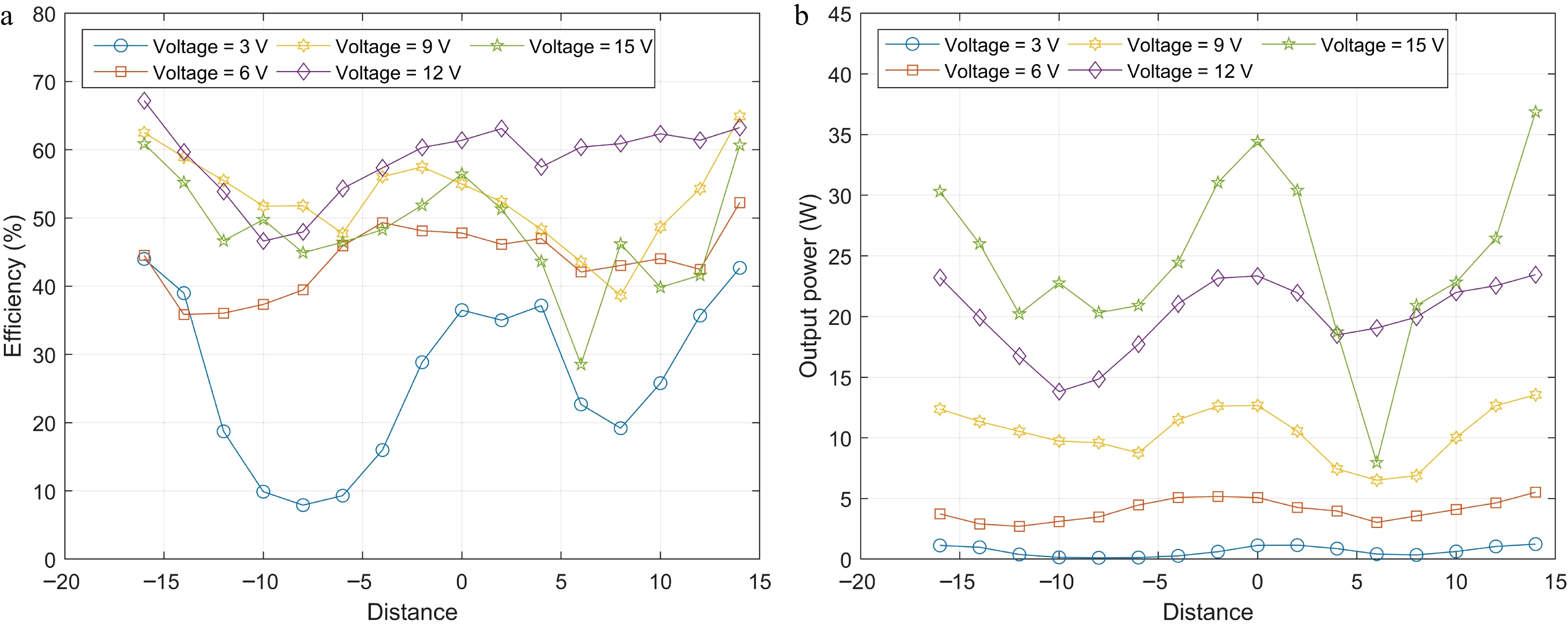
Figure 17.
(a) Efficiencies, and (b) output powers of the WPT system at different voltages in Experiment A when the shielding coil is perpendicular to the transmitting coil.
(1) The most significant decreases in transmission efficiency and output power occurs approximately −10 to −6 cm and 6 to 8 cm away from the transmitting coil. Given that the outer diameter of the shielding coil is about 11 cm, it can be inferred that at these distances, roughly half of the shielding coil is adjacent to the transmitting coil, where the eddy current effect is most significant. Therefore, shielding coils positioned at these locations have the greatest impact on the normal operation of the WPT system.
(2) At locations far away from the transmitting coil, the transmission efficiency and output power are comparable to those observed without a shielding plate.
(3) Between x = −2 to 0 cm, the output power reaches its peak, while between x = 0 to 2 cm, the transmission efficiency peaks. Therefore, placing a shielding coil between the transmitting coil and the receiving coil can achieve a more effective shielding effect.
Results of Experiment B
-
As shown in Fig. 18, 19 and 20, it is noticeable that placing the shielding coil perpendicular to the transmitting coil yields similar conclusions to Experiment A. Since the shielding coil is at the resonance frequency in Experiment B, it can be demonstrated that there is a shielding effect under this condition also. Among the various cases, Case b demonstrates the best overall shielding effect, not only reducing output power but also having a lower impact on efficiency compared to the other cases.
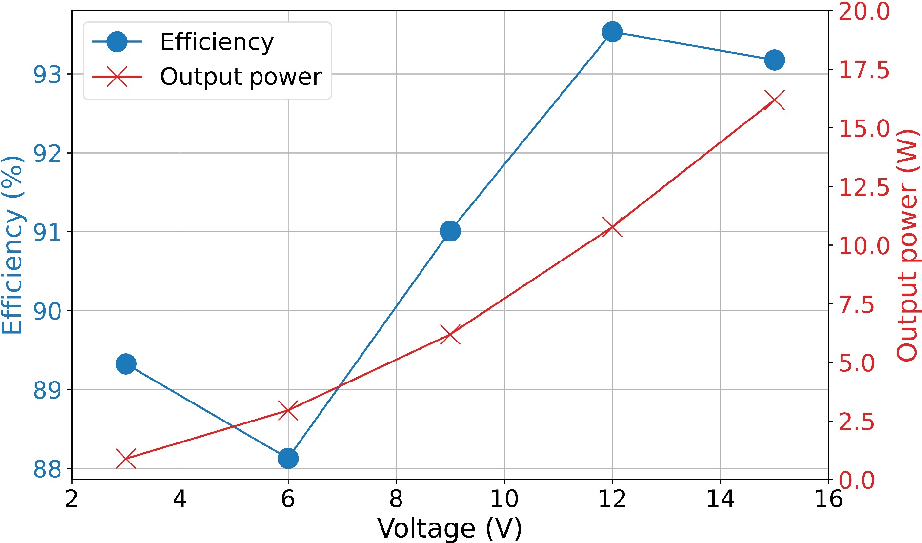
Figure 18.
Efficiency between resonator or WPT system and output power of Rx coil or rectifier bridge in Experiment B.
-
This paper presents a design for a frequency-adjustable PCB shielding coil tailored for WPT systems operating at various frequencies. The operational frequency of the coil is adjusted by changing the value of the parallel capacitance. By fitting the value of inductance, the optimal parallel capacitance is determined. Experimental results demonstrate that the shielding coil effectively reduces electromagnetic interference while maintaining high transmission efficiency in WPT systems. This highlights the effectiveness of the proposed design in enhancing the functionality and adaptability of shielding solutions for WPT applications.
-
The authors confirm contribution to the paper as follows: conceptualization: Yang Y, Yang J; data curation: Shang S, Zhang X, Yang J; formal analysis: Yang J, Wang K; funding acquisition: Yang Y; investigation: Yang J, Shang S, Wang Y, Wang K; methodology: Yang J, Zhang X; project administration: Yang Y, Wang K, Yang J; resources: Yang Y, Zhang X, Yang J; software: Yang J, Zhang X, Wang Y; supervision: Yang Y, Wang K; validation: Yang J, Zhang X, Wang Y, Wang K; visualization: Zhang X, Wang Y; writing - original draft: Yang J; Writing - review & editing: Wang K, Yang Y. All authors reviewed the results and approved the final version of the manuscript.
-
The data that support the findings of this study are available from the corresponding author upon reasonable request.
The authors are grateful for the financial support from the Ministry of Education (MoE) Academic Research Fund (AcRF) Tier-1 RG134/23 and the A*Star MTC Young Individual Research Grant (YIRG) M23M7c0115.
-
The authors declare that they have no conflict of interest. Yun Yang is the Editorial Board member of Wireless Power Transfer who was blinded from reviewing or making decisions on the manuscript. The article was subject to the journal's standard procedures, with peer-review handled independently of this Editorial Board member and the research groups.
- Copyright: © 2024 by the author(s). Published by Maximum Academic Press, Fayetteville, GA. This article is an open access article distributed under Creative Commons Attribution License (CC BY 4.0), visit https://creativecommons.org/licenses/by/4.0/.
-
About this article
Cite this article
Yang J, Zhang X, Wang Y, Shang S, Wang K, et al. 2024. A frequency-adjustable PCB shielding coil in Wireless Power Transfer system. Wireless Power Transfer 11: e006 doi: 10.48130/wpt-0024-0008
A frequency-adjustable PCB shielding coil in Wireless Power Transfer system
- Received: 08 July 2024
- Revised: 15 August 2024
- Accepted: 04 September 2024
- Published online: 12 October 2024
Abstract: This paper presents the design of a frequency-adjustable PCB shielding coil for Wireless Power Transfer (WPT) systems. A simplified equivalent circuit model of the PCB coil is provided and the main parameter estimations for the PCB coil are implemented. The proposed shielding coil can reduce the electromagnetic field leakage without significantly impacting the transmission efficiency of the WPT system. Adjusting the resonant frequency of the shielding coil by changing the resonant capacitor makes it suitable for WPT systems operating at different frequencies. Experiments conducted on WPT systems operating at 100 and 200 kHz confirm the effectiveness of the shielding coil.
-
Key words:
- PCB shielding /
- Frequency adjustable /
- Active shielding


