


-
The worldwide consumption of energy is rapidly increasing as a result of industrialization and growing population. The projected increase in global energy usage between 2018 and 2050 is approximately 50%. Fossil fuels, which are harmful to the environment, have historically been the main source of energy to fulfill the increasing demand[1]. Due to the greenhouse emission effect, burning fossil fuels releases huge amounts of pollutants into the atmosphere, such as carbon dioxide (CO2), which detrimental human health and contributes to global warming[2,3]. The two main reasons for this are a shortage of supplies and the damaging consequences of traditional approaches on the natural world. Furthermore, future usage of these forms of energy is likely to be limited[4,5]. Many educators are motivated by these reasons to pursue careers in the area of energy from renewable sources.
To reduce the amount of carbon dioxide in the atmosphere and thus slow global warming, renewable energy sources must be utilized[6]. These sources not only provide an inexpensive alternative to fossil fuels but also have the potential to connect distant, urbanized, and rural locations with power[7,8]. The transition to energy from renewable sources represents one of the most important developments of the twenty-first century. Renewable energy sources (RESs), such as photovoltaic panels (PV), thermal solar electricity, hydroelectricity, geothermal electricity, wind, and biomass, could offer everyone, regardless of the location, affordable alternatives and ecologically beneficial power[9,10]. Among these options, solar power is often employed in two configurations: independent as well as connected to a network[11]. Panel one's load voltage must be permanently adjusted due to variations in solar power[12]. Installing a converter that converts DC to DC with an MPPT technology will allow for this adaption. This method guarantees that the PV panels will recover the maximum amount of electricity they produce.
Energy produced from Renewable energy sources (RESs) climbed by over 8% to 8,300 TWh in 2021, marking the largest yearly rise in over 40 years. Nevertheless, the first transmission level (230 kV) photovoltaic system established in the USA was noticed worldwide when it was built in Florida[13]. As a consequence, enthusiasm for installing large-scale PV (transmission and sub-transmission levels) grew quickly, and by the last quarter of 2018, the total capacity that had been installed of PV worldwide exceeded 505 GW. Figure 1 shows the overall PV capacity put in place from 2008 to 2018. The total capacity being installed in PVs climbed from 15 GW in 2008 to 505 GW by the last quarter of 2018[14], indicating a tremendous rise in PV installations. Because of the rising energy output of all renewable energy (RES), it is expected that by the year 2020, the share of power produced by green energy would reach 30%[15]. In 2021, the electricity generated by renewable power stations increased by 257 GW (+9.1%), which brings the total amount of energy from renewable sources generated to over 3,064 GW. Wind energy came in second with 93 GW (+13%), behind solar energy, which continued to lead this energy boom with an addition of 133 GW (+19%). By 2040, the usage of photovoltaic cells is anticipated to have become the renewable energy source that contributes the greatest amount to the generation of electricity[16,17].
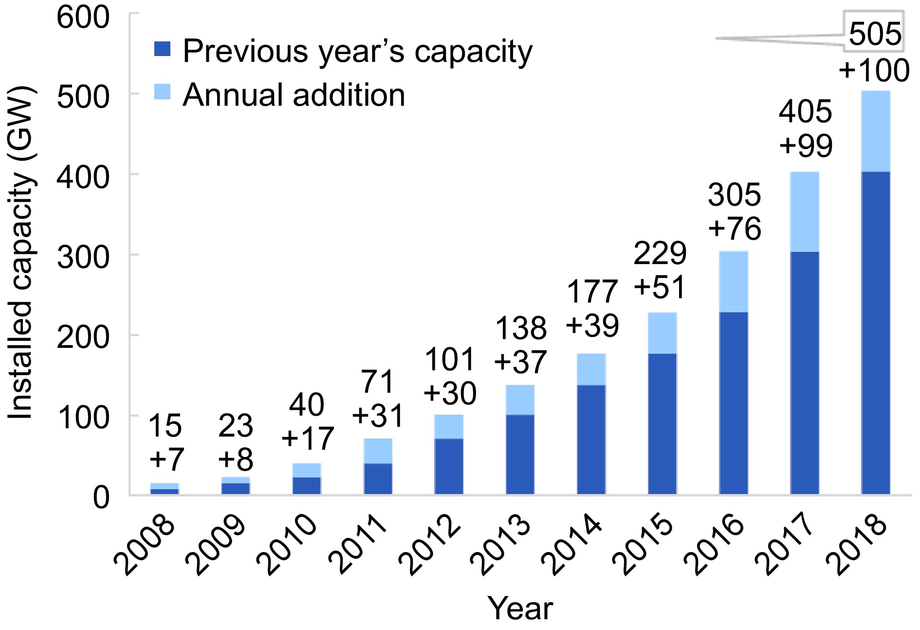
Figure 1.
Overall constructed solar energy production from 2008 to 2018[14].
Due to its abundance in the natural world, solar power seems to be a major contender amongst all-renewable energy sources. Photovoltaic, or PV, systems may provide environmentally friendly and environmentally friendly power to far-flung areas, among other advantages[18,19]. They can be positioned in commercial or residential buildings to meet partial or whole load requirements. The extra energy can be sent back into the grid if the solar power plant provides greater power than is needed to meet requirements[20]. Increased initiatives pertaining to investigation and development are necessary in several sectors due to the growing need for solar power systems. To address the concerns raised by those creating PV systems, energy companies, as well as users, cheaper and more effective photovoltaic panels have been developed. The amount of solar energy and the array's exterior temperature have an impact on its production[21]. Utilizing electromechanical solar tracking devices can produce the most power from the array while maximizing the amount of illumination received[20]. A Maximum Power Point Tracking (MPPT) method is utilized to operate the PV array at approximately its optimum power production for a certain load when the outside conditions vary[22].
This research presents an in-depth simulation of a 12.5 KW photovoltaic (PV) system linked to a three-phase line with a voltage factor equal to one and running during continuous sunlight. Modeling has been done for DC-to-DC boost as well as DC-AC conversions across two phases. To maintain a constant DC, and link the voltage, and the operation cycle in the boost converter that switches between DC and DC is closely monitored[23,24]. One of the essential components in turning solar energy into electricity is the inverter[18]. To extract the maximum amount of electricity generated by the panels, additional direct current (DC)-DC converters are included inside the inverter[25,26]. The three-phase Voltage Source Inverters (VSI) utilize the voltage from the DC link as their input, and to manage the current flowing across the electrical system in the simultaneously rotating frames of a reference, they employ Voltage Orientation manage (VOC) and a decoupling regulator. This study's main objective is to use a potent algorithm known as MPPT to optimize the quantity of electricity produced by a solar photovoltaic (PV) system. This is accomplished by ensuring that the injection AC current conforms with the requirements of the IEEE by monitoring the MPPT technique's efficacy and, subsequently, its efficacy in addition to the integrity of the AC current[27,28].
-
The production of solar power is increasing in popularity because of its ubiquitous accessibility, minimal upkeep needs, etc[22−29]. There was much discussion about the mathematical simulation of the solar photovoltaic (PV) system in previous research[30−32]. Power-switching equipment enables the photovoltaic (PV) solar power system to operate at MPP in an array of conditions of the atmosphere[33]. A method of producing energy that operates by the warmth of the sun, a never-ending supply of pure, unlimited energy, is known as Concentrated Solar Electricity (CSP). This type of solar energy production often serves as a massive, concentrated supply of power for utilities[34] as well as requiring a lot of direct sunshine. The plurality of MPPT algorithms utilized to manage these power-switching components in the photovoltaic (PV) system includes P&O, Increment Conductivity (IC), and fuzzy logic controller (FLC), as well as others[35]. The P&O method takes into consideration the slope of the curve known as P-V to select a new functioning point[36]. A DC-DC booster converter is one of the inner stages described by the investigation. It immediately changes by monitoring the quantity of solar output electricity as well as the duty period of the drive-switching pulse[37]. Besides providing access to a revised unipolar in nature Sinusoidal Pulse Width Modulation inverter (PWM), the method offers an improved SPWM converter with an adjusted, more powerful reference waveform compared to the regular SPWM as well as a converter with Zero crossing Detection circuits[38]. Compared to a source of AC electricity like a three separate phases grid, which is indefinitely competent, the DC voltage generated by a PV array is far less valuable. As a consequence, various attempts at DC to AC conversion have previously been made[39]. Single-stage and two-stage converting procedures are both accessible[40]. Regardless of all the presently available techniques, the P&O MPPT approach is the one that is most frequently used[41]. Even though the gradual permeability technique is faster than P&O, it is still quite slow for devices that are connected to the grid since it needs to do computations to keep track of its heading toward the center (maximum power point)[42]. Particle swarm optimizing, fuzzy theory, and genetic algorithm development are some of the instruments for subsequent generation approaches. Contrarily, rigorous methods are implemented for conventional approaches, including linear programming (LP). The study authors proposed that an inverter uses a suitable voltage-regulated oscillation (VCO) to provide variable frequency carriers controlled by standard voltage from the grid produced by a full rectification wave[43]. Following thorough adjusting, fuzzy logic-based techniques offer quick responses, but they have problems with implementation as well as need previous information to establish the fuzziness parameters for the technique. An overview of P&O techniques can be found in Attia et al.[42]. This method claims that energy is lost as a result of the point of operation oscillating around the point of greatest power. While decreasing the fixed disturbance size of steps might lessen these fluctuations, it will take longer to reach MPP. To deal with this troublesome situation, an improved P&O algorithm for MPPT featuring adjustable step size is presented. Since a PV module's production is a DC and the electrical grid's interface requires AC electricity, a DC-AC converter is required[44]. The MultiStart optimization (MS) algorithm-based PI (MS-PI) used in this study to manage the index of modulation under various load scenarios results in a superior voltage regulator for freestanding solar power inverters[45].
Various methods have been used in literature to regulate Maximum Power Point Tracking (MPPT) systems. The most commonly used methods are Incremental Conductance (IC) and Perturb and Observe (P&O), which are categorized based on the electrical power or current characteristics used for control loops[46,47]. The indirect control approach of active and reactive power was developed based on the field orientation control (FOC) for induction motors. Voltage-oriented control (VOC) involves orienting voltage vectors with respect to current vectors[48]. In PWM converters, measurements of input voltage and current are utilized by additional controllers to determine active and reactive power. Direct Power Control (DPC) is a method of instantaneous power control that uses switching tables and hysteresis comparisons[49]. Despite offering superior dynamic behavior, DPC has a few shortcomings. It cannot achieve a constant switching frequency and requires a high sampling frequency[50]. Virtual Flow-based DPC (VFDPC) and Virtual Flux-based VOC (VFOC) techniques are utilized as the foundation for further controls that use virtual flux to estimate voltage[51,52]. In their paper, Ouchen et al.[52] propose a direct power control method (DPC-SVM) based on vector modulation. The method involves the use of a PI/PID controller to keep track of the loop reference. By adjusting the controller settings, the system's behavior can be made dynamic and steady[53]. The controller's high performance ensures improved quality and robustness of the control. A new type of control called Fractional Order PID (FOPID) was developed by modifying the integration sequence of the conventional PID control system to a fractional one[54]. The FOPID configuration controller is known for its improved specified responsiveness and ability to adapt to changes in the controlled device. Tuning the FOPID variables enhances the responsiveness and strengthens the resilience of the controlled device when compared to a standard PID-controlled system[55]. In their publication, Jain & Saravanakumar conducted a thorough analysis of FOPID and traditional PID control systems[56,57]. The FOPID was used by Kakkar et al. to manage the flux-oriented virtual control of a PWM converter linked to the electrical grid[58]. The simulation results showed that the FOPID algorithm significantly increased the injected electrical performance compared to a traditional PID control system. Additionally, the FOPID algorithm proved to be less susceptible to loads and variable fluctuations. To improve the responsiveness of the automatic voltage regulator (AVR) system, a fractional filter was suggested and applied to the FOPID control system. This approach, known as SCA-FOPIDFF control, resulted in a significant enhancement of the AVR system efficiency[59]. Regardless of the type of controller used, whether PID or FOPID, tuning the settings is essential for the converter to respond satisfactorily.
Based on a thorough analysis of numerous studies and publications, Table 1 provides a summarized view of scientific articles. The table discusses different characteristics such as the type of DC-link and current controller used in various reference structures to regulate energy current or voltage in 1-phase or 3-phase inverters. It also highlights the number of modulation approaches, filter types, and feedback loop counts used in different grid-connected implementations. From the aforementioned articles and the research papers presented in Table 1, it can be inferred that each of these controls has certain limitations and challenges.
Table 1. Key features of various controllers suggested in scholarly works.
Ref. NOP, CRF CC DLC FL CP F MT A [60] 3-PH DP, PI DB M-L C, V LCL DPWM G [61] 3-PH Active recative control PI, PR M-L V, P L PWM G [62] 3-PH MPC − S-L V, C L PWM PV [63] 3-PH MPC − S-L C LCL PWM G [64] 3-PH Fuzzy PI M-L V, C L SVPWM PV [65] 1-PH Fractional order PR − M-L C, P L SPWM PV [66] 3-PH Fractional order PI Fractional order PR M-L V, C LCL PWM PV [67] 3-PH PI PI M-L V, C LCL PWM PV [68] 3-PH PR PI M-L V, C LCL PWM PV [69] 1-PH FuzzySMC − S-L V L PWM PV [70] 3-PH PI PI M-L V, C L SVPWM PV [71] 1-PH PI, MPC PI, MPC M-L V, C L PWM PV [72] 3-PH PI, Vector control PI M-L V, C L PWM PV [73] 3-PH Fractional order SMC − S-L C L PWM PV [74] 3-PH MPC − S-L C LCL PWM G [75] 1-PH Fractional order RC − S-L C LCL PWM G NOP: Number of Phases, CRF: Control Reference Frames, CC: Current Controller, DLC: DC-Link Controller, FL: Feedback Loop, CP: Control Parameters, F: Filter, MT: Modulation Technique, A: Application, M-L: Multiple loop, S-L: Single loop, V: Voltage, C: Current, P: Power, and G: General. The study mentioned earlier makes it evident that it is impossible to forecast which of these dispatching methods would far exceed the other in terms of system efficiency. The feasibility of supplying an Iraqi home's power demands with a grid-connected PV system is investigated in this study. Utilizing HOMER's MATLAB Linking software and taking into account forecasts of both demand for electricity and potential solar production of cells, an enhanced dispatch approach is developed. Depending on the anticipated information, the apparatus operates at its most effective and efficient levels. In order to contrast the developed plan with the standard techniques of loading follow (LF) and cycling charge (CC) for the HES, a techno-economic and environmental assessment is conducted[76].
-
Both topological and quantitative methods can be used to conduct visibility studies of electrical networks. However, because numerical methods have limits, the majority of investigators prefer to use topology methodologies based on graph theory. These restrictions include the Jacobian matrix method's uniqueness problems and computational difficulty[18]. Topological methods can yield the same outcome as their mathematics counterparts without significant challenges[34]. Two key concepts can be used to characterize the issue of a large-node electrical distribution system when using the topological method: enhancing power flow, guaranteeing stability, and raising efficiency. Important things to consider are as follows:
Optimal Energy Flow (OEF): Create formulas that maximize power flow while accounting for limitations including voltage limits, transmission capacities, and generating limits.
Voltage Stability: Resolving problems with voltage stability by developing formulas to keep voltages within reasonable bounds while accounting for generator reactive power support and appropriate grid connectivity.
The principles of topological monitoring and analysis of electronically transmitted networks are well understood. The same criterion will be applied to this study's examination of distribution networks' apparent transparency.
-
Definitions state that microgrids are 'virtually autonomous low-voltage and/or medium-voltage networks equipped with additional facilities collecting and managing their own supplier and demand-side resources, possibly also in the event of islanding'. An MG device with power conversion units (PCs), electricity consumers (loads), as well as Distributed Energy Resource (DERs) such RESs, CGSs, and ESSs is shown in Fig. 2[38]. The MG system trades surplus power with the main grid in exchange for payment while it is in grid-connected mode. A centralized controller and local controllers (LCs) are used to operate the system. In MG, effective DER management and cooperation increase system performance and foster equitable growth.
The Microgrid (MG), when linked to the grid, adjusts electricity supply and demand to meet load and capacity requirements, all the while adhering to market laws and maximizing cost and efficiency. In the same vein, it can cut off from the main electrical system in the case of an interruption while continuing to supply associated major loads with electricity. SCADA technology is included in the MG to ensure dependable and economical operation. For the microgrid (MG) to operate in a stable, trustworthy, and economical manner, the control system must efficiently manage all the distributed energy resources (DERs).
-
The primary diagram of a solar energy system that connects to the grid is shown in Fig. 2. There are two different configurations for grid-dependent solar power plants; the three-stage configuration is the most popular. In the dual-stage installation process, PV as well as the network are intertwined with both power converter phases (DC-DC, DC-AC). PV panels, a DC-DC conversion, a DC-AC inverter, and an electrical system are the components of a network-connected PV construction. In the recommended system the DC-to-DC conversion is performed by a converter known as a boost, and the incorporated MPPT controller maximizes the output of each PV module. Using DC-to-AC conversion devices, the solar energy (PV) system is connected to the electrical grid. A three-level inverters and converters are used for converting DC to AC.
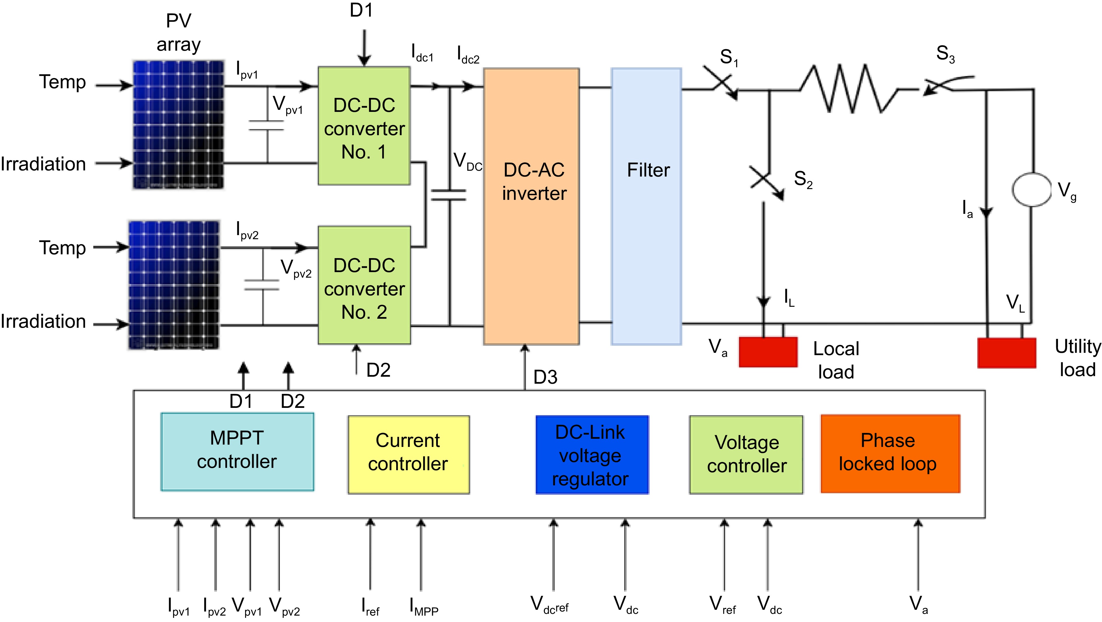
Figure 2.
Overall system design[76].
Design of the inverter controller
-
In order to connect a photovoltaic array to the AC bus, a power inverter is necessary. A three-phase inverter, when connected to the system, receives a steady DC power supply from the booster converter. These types of inverters are used only in systems that require them. They generate a three-phase voltage (va, vb, and vc) and are capable of producing a significant amount of power.
The primary function of voltage source inverters (VSI) is to convert a steady voltage of DC producing a three-phase alternate current voltage with adjustable frequency and magnitude. A triple-level conversion with three bridging legs that are neutral-point restrained is used in the current work. According to Fig. 3, every bridge leg—A, B, and C—can be in any three different voltage indicates, which are referred to as having 'three' in this setting. A converter's architecture is shown in Fig. 3.
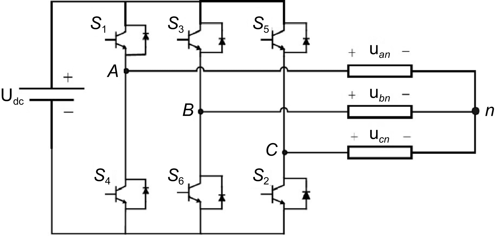
Figure 3.
Three phase voltage source inverter.
The integrated circuit is turned ON and OFF to supply the necessary outputs and thus produce the AC voltage result of the inverters. Pulse width modulation (PWM) techniques are frequently used to carry out this function. It should be taken into account that to prevent the short circuit of the DC supply, the switches on each leg should be actuated alternately. Integrated Gate Bipolar Transistors (IGBTs) and power MOSFET components can be used for the implementation of switching. The power ratings and switching speeds of each device vary. As seen in Fig. 4, IGBTs are ideally suited for applications requiring medium power as well as switching frequencies. Every piece of equipment has a different switching speed as well as power rating. IGBTs have the greatest potential for uses needing moderate power consumption as well as switching frequency, as can be shown in Fig. 4.
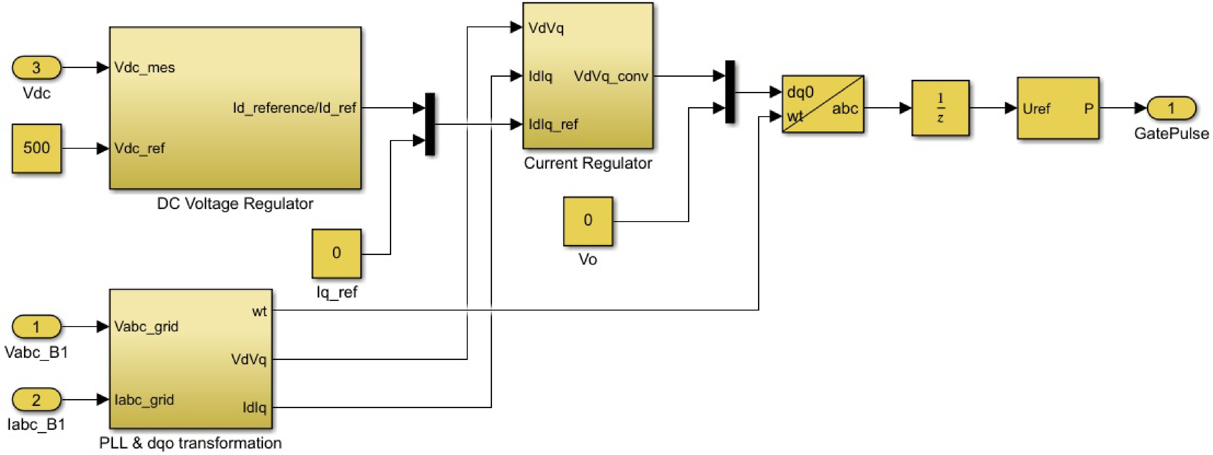
Figure 4.
Design of the optimal controller.
Maximum power point tracking
-
Temperature variations, variations in the sun's direction, and variations in the amount of sunlight all affect the solar PV module's power generation. There is also a single maximum power point in this specific working situation of the PV features. The photovoltaic panel should ideally function near this point, meaning that its output should be getting closer to the MPPT. Maximum power point tracking is the procedure of running a photovoltaic module under certain circumstances (MPPT). Optimizing photovoltaic power enhances the sunlight's PV module's use[75].
There have already been several algorithms for MPPT put out in previous years. The works featured here contain two comparisons among them. These days, the P&O and the incremental permeability approach are the most often used techniques[76]. There is also a description of the Hill climbing method in[77]. The suggested model makes use of the gradual conductance approach as it has the primary benefit of offering high effectiveness in quickly changing environmental circumstances. However, if it was necessary for the modeling, we might employ an alternative MPPT method. The output current of the PV array serves as the technique's foundation and is continuously adjusted to attain the voltage at the maximum power point (MPP).
Design of DC-to-DC converter
-
An unregulated direct current (DC) supply voltage is converted to the regulated direct current voltage that outputs at a specified voltage level using a switched-mode DC-to-DC converter. Switching sources of power offers substantially improved effectiveness as well as energy density as opposed to a linear power supply. Typical parts of fundamental conversion that step upward or lower the source voltage include transistors, diodes, capacitors, as well as inductive devices. Buck (step-down), boost (step-up), and buck-boost (step-up or step-down) have been the three main converter configurations. In our recommended design, the boost topologies are utilized due to its free-wheeling diode's potential to be employed to avoid the reverse current and effectively increase PV array voltage generation to a higher level.
It is feasible to control converters utilizing a pulse width modulation (PWM) rate of duty while the resultant voltage of a conversion is dependent on the current state of the transistor switch. The optimal load resistance of the photovoltaic panel is therefore achieved by varying duty cycles. The boost DC converter increases its input voltage by momentarily storing the energy within an inductive element and utilizing the stored energy to increase the supply voltage to a greater amount. The layout of the circuit for a converter that produces a boost is shown in Fig. 5.
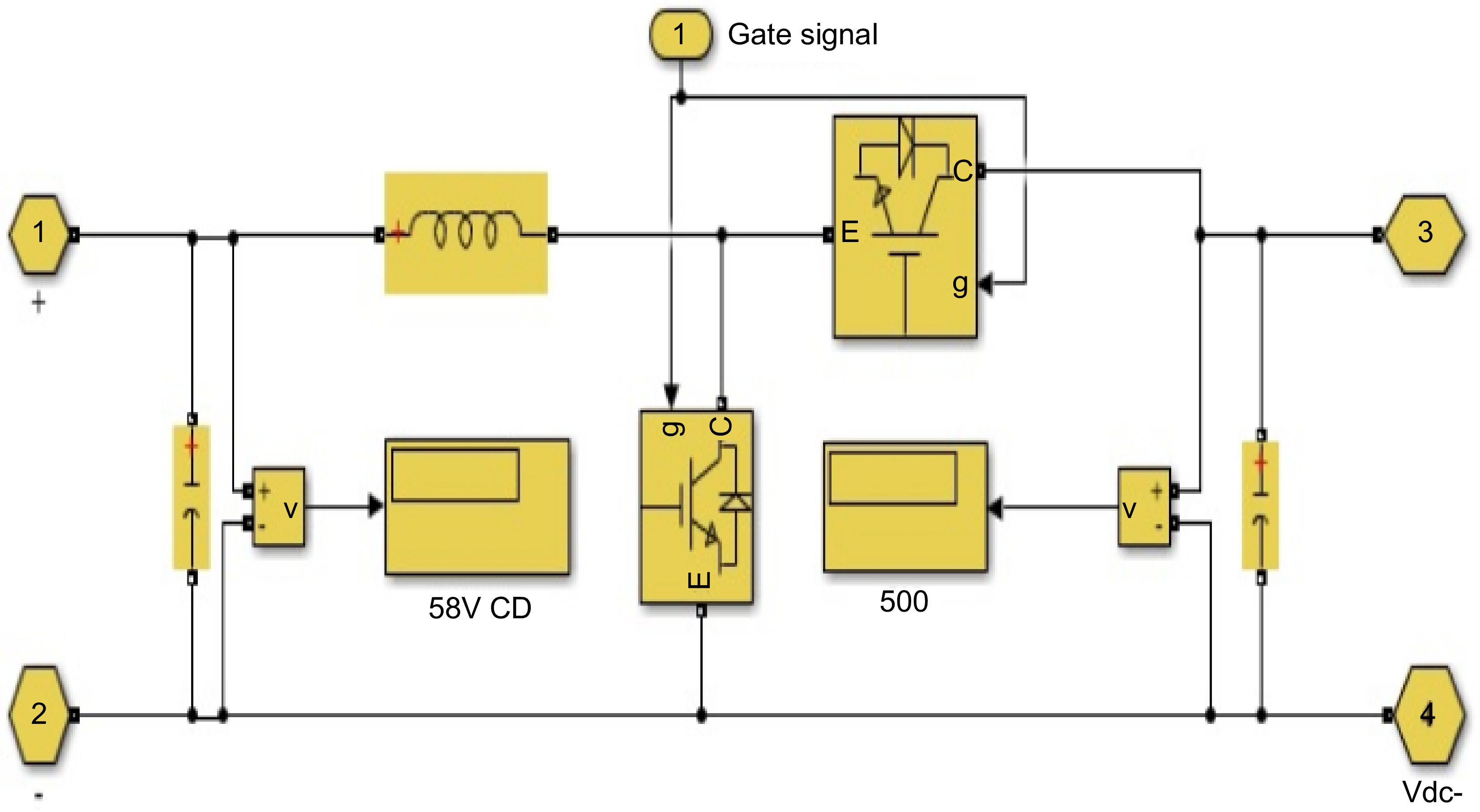
Figure 5.
Design of bidirectional DC-DC converter.
To create separation among the converter's internal components, an inductor is charged up while switch G is closed. Diode D has reverse bias at both the point of input and the final result. When a switch is turned, electricity is stored in the inductor before being transferred to the demand. The grid and inverter characteristics taken into account while developing the filter are shown in the following Table 2. L's value is calculated using the current ripples. Reduced ripple results in reduced switching as well as conducting losses.
Table 2. Design parameters.
Details Value Grid line voltage (V L-L) 415 V Grid phase voltage (Vph) 240 V DC source voltage (Vdc) 250 V Output power fed to grid (Pn) 1,000 W Grid Frequency (f) 50 Hz Switching frequency (fs) 20 KHz -
The general architecture of the system's components is simulated for a variety of temperatures, radiation, and grid circumstances. A review and assessment of the results in relation to several assumptions were done. Figure 6 and Table 2 illustrate the structure of the system in its entirety. The presumption is that the photovoltaic array consists of two parallel lines. On every link, 10 Tata Power's solar System TP300LBZ solar cells are sequentially linked. A maximum electricity capacity of 6 kW is generated by the photovoltaic system at STC (1,000 W/m2 of solar radiation with a temperature of 25 °C). Utilizing a DC-DC Boost Converter, the solar array MPP's electrical output is raised from (389 V at STC to 700 V). The power conversion uses a 10 kHz changing frequency. The cycle of duty for the Boost conversion is generated by the MPPT algorithm.
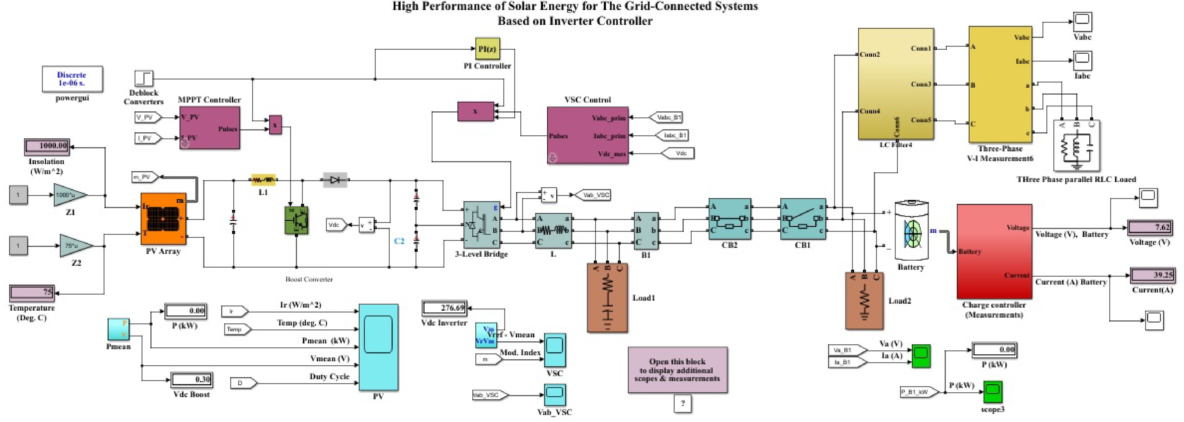
Figure 6.
The overall system of solar energy for the grid-connected systems based on optimal controller.
The Permeate functions (P&O) approach is used by the MPPT Controller to create the results frequency of the power converter. This controller modifies the rate of duty of the booster converter continuously to maximize the amount of power produced by the photovoltaic array. The 700 V level of voltage has been converted into a 415 V rms line-to-line voltage using a voltage converter. The inverter's IGBTs are regulated using PWM. The PWM impulses are generated by the inverter part of the regulator. To generate the required (AC) voltages, currents, and power, the IGBTs within the inverter require the appropriate gate pulses generated by the VSI Controllers. The Grid Functions LCR filter is employed to filter away overtones from the inverter's outputs. A 415 V grid connects the photovoltaic system to the power grid.
The beginning of the simulations is done by increasing irradiation from (0 to 1,000) W/m2 at 25 °C by the STC given in Fig. 7. Several deductions may be made from the image: The target figure is 800 V DC, which is the voltage value. As solar radiation increases, the PV electricity voltage, and current will additionally increase, automatically boosting the resulting power. The inverter's power output of 5,860 W (the PV panel power is 6 kW) corresponds to 96% of its theoretically maximum efficiency.
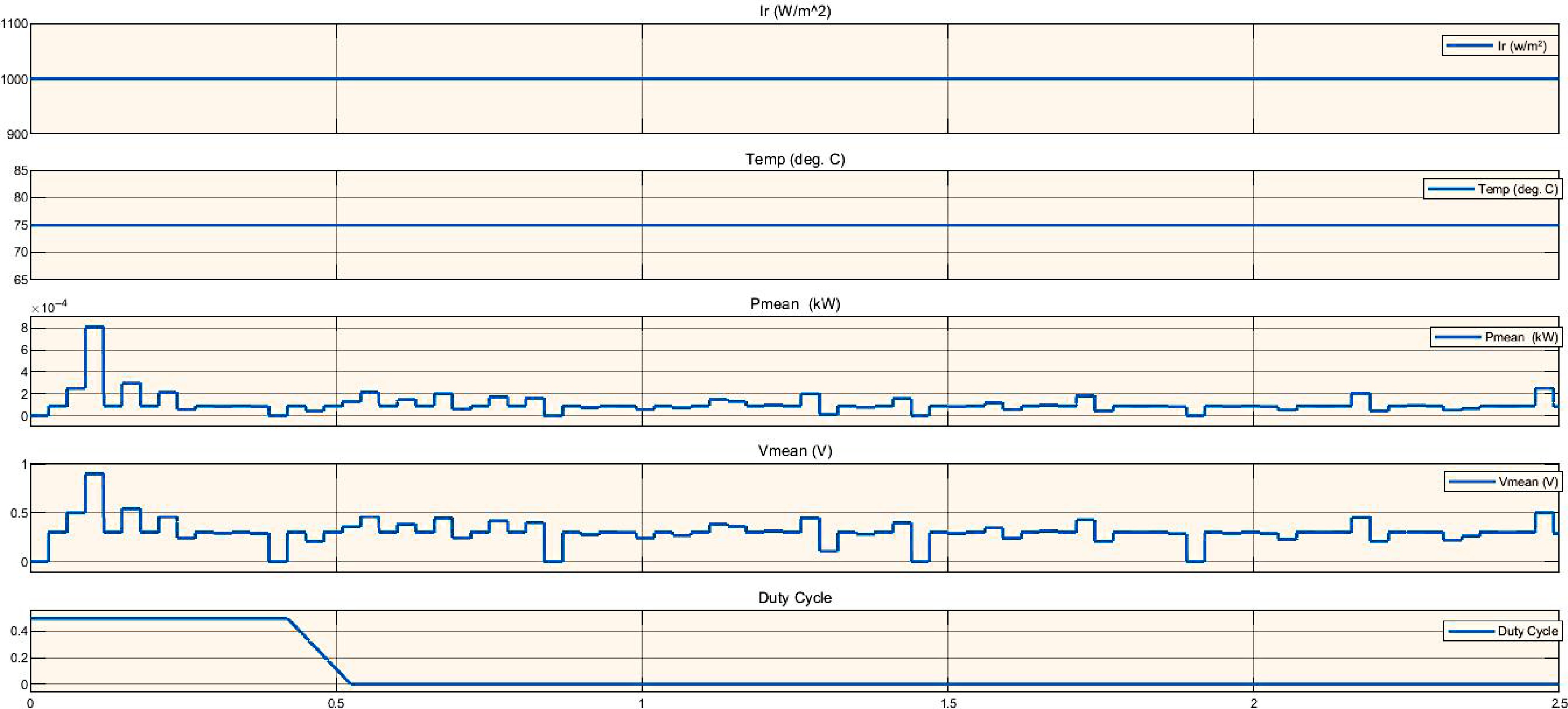
Figure 7.
Simulation of PV system analysis based on irradiance affect.
In this research, work is being done to achieve the optimal performance of the power system consisting of more than one source, which represents the microgrid in the production of electrical energy. Therefore, work is being done to reach the best performance in solar panels, relying on obtaining the best times for radiation intensity, as well as working to reach the optimal performance of the electrical power controllers during the injection process in the central network to avoid synchronization problems in the injection operations and to avoid wasting the energy produced by clean sources of electrical energy production. Therefore, this research was conducted on more than one scenario to reach the best performance of the micro mail system that works to produce energy, its management, and the optimal method
The additional calculation is done by the STC given in Fig. 8 by increasing the ambient temperature from 0 to 25 °C while keeping a constant irradiation of (1,000 W/m2). The results of the experiment are shown in Fig. 8. Figures are able to be used to make the corresponding outcomes: (800 V DC) is the connecting voltage of DC. This is the ideal value. As the outside temperature increases, the PV voltage as well as current will fall, which will result in a visible reduction in the power produced. The resultant power of the inverter is comparable to 5,200 W, which shows a drop in inverter effectiveness.
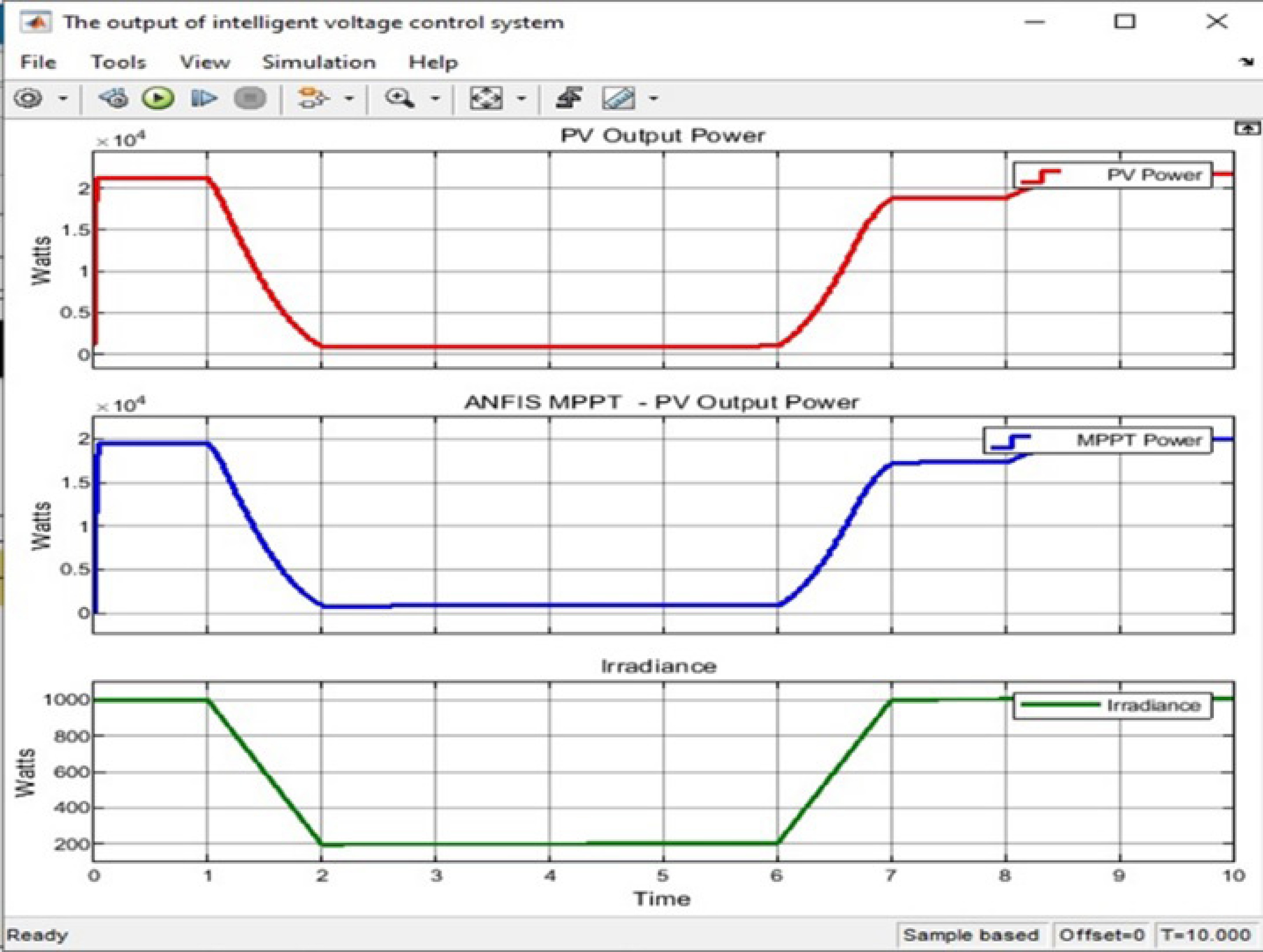
Figure 8.
The output ANFIS controller based on MPPT.
STC-compliant temperatures are upheld while the PV system's modeling is carried out using a linear demand which illustrates the results of the experiment. The results allow for the subsequent inferences: Voltage and current waveforms are symmetrical and have smooth peaks. Despite keeping STC requirements for temperatures as well as irradiance, the modeling is conducted with a non-linear demand in the solar system as a whole. Figure 9 shows the simulation results for the whole system architecture.
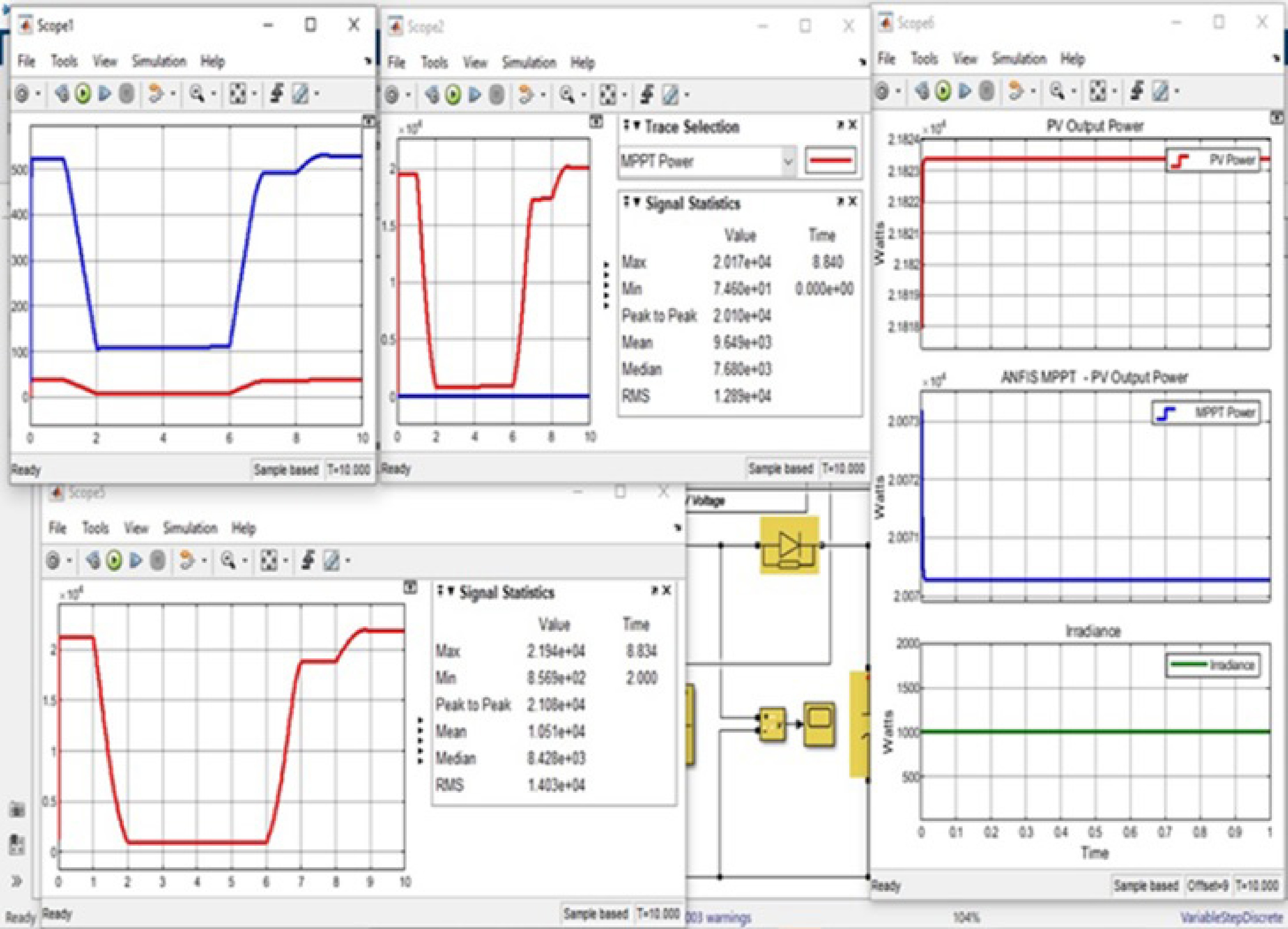
Figure 9.
Overall simulation for optimal controller of solar energy with grid-connected systems.
-
This work provides and performs a complete simulation of the full Grid-Connected solar energy system using the simulation software MATLAB/Simulink. The simulation is simple and precise, and it accurately replicates a real Grid-Connected photovoltaic (PV) array. To coordinate the current of a three-phase electrical converter to the electrical network and construct a voltage-oriented control scheme, the simulation uses a decoupling regulator as well as a centralized control system on the top for the direct delivery of both reactive and active energy to the grids. The method in question reaches MPPT and has 99.4% detection accuracy. The simulation results for an array of solar cells have been compared with the genuine Tata Energy solar panel datasheet, and they also closely resemble the actual information.
To reduce losses during switching and increase the efficiency of the solar system, PWM is applied to the signals of the individual IGBTs in the inverters. The results of the experiment show that the system being simulated operates effectively under a variety of temperature and irradiance circumstances. Furthermore, it illustrates how linear and non-linear demands affect a solar energy system. To deliver active power to the grid, the inverter's operation is managed via synchronized d-q conversion. To ensure grid phases and frequency, PLLs are used. The three-phase system's d-q adjustment is used to effectively finish the phase identification stage of the PLL. Given the aim of mimicking a real connected-to-the-grid solar power plant, the PV prototype, the DC-to-DV conversion model, and DC-to-DC converter management ought to be included.
-
The authors confirm contribution to the paper as follows: writing - draft manuscript preparation, applied the results and discussion: Al Mashhadany Y; conceptualization, methodology: Al Mashhadany Y, Al Smadi T, Abbas AK; investigation: Al Smadi T, Abbas AK; writing - manuscript review & editing: Algburi S, Taha BA. All authors have reviewed and accepted the published version of the manuscript.
-
All data used in the implementation of this work is available upon reasonable request from the corresponding author.
The authors would like to thank the Ministry of Higher Education and Scientific Research of Iraq, University of Anbar, College of Engineering, Ramadi, Iraq, for supporting as of applied this work.
-
The authors declare that they have no conflict of interest.
- Copyright: © 2024 by the author(s). Published by Maximum Academic Press, Fayetteville, GA. This article is an open access article distributed under Creative Commons Attribution License (CC BY 4.0), visit https://creativecommons.org/licenses/by/4.0/.
-
About this article
Cite this article
Al Mashhadany Y, Al Smadi T, Abbas AK, Algburi S, Taha BA. 2024. Optimal controller design for high performance of solar energy for grid-connected systems. Wireless Power Transfer 11: e007 doi: 10.48130/wpt-0024-0005 

Optimal controller design for high performance of solar energy for grid-connected systems
- Received: 10 April 2024
- Revised: 23 July 2024
- Accepted: 21 August 2024
- Published online: 22 October 2024
Abstract: Engineers are searching for alternatives to conventional sources of electricity to solve the energy crisis as a result of the sharp increase in energy usage. The design, simulations, and investigation of a three-phase, 10.44 kW solar energy system are presented in this study. PV analysis is also done. The photovoltaic system consists of six concurrent strings, each consisting of four photovoltaic cells connected in series, and an inverter that provides a two-way flow of energy. The output of a Phase Lock Loop (PLL) comments linearization system is utilized for generating a signal, and the power converting voltage is synchronized with the signal using this reference voltage. Two stages that are most appropriate for the battery's rechargeable charging process are chosen to replenish a battery bank in either quantity or float arrangement for eight sequences of 12.5 V and 200 Ah rechargeable battery packs. The designed photovoltaic (PV) system falls under the category of hybrid systems. Not to mention, a MATLAB computer model has been developed for a grid-dependent solar PV system that makes use of a sinusoidal pulse width modulator and a voltage source inverter.
-
Key words:
- High performance /
- Photovoltaic (PV) systems /
- DC-DC converter /
- Phase lock loop /
- Grid synchronization