










-
Wireless power transfer (WPT) technologies are characterized by electrical isolation, convenient operation, and high safety, which are applied in various application scenarios, including electric vehicles[1], consumer electronics[2,3] and medical equipment[4]. However, since primary and secondary coils are connected without physical contact, variations in the coupling coefficient, or load may cause fluctuations in both transfer efficiency and output power[5].
Basic compensation topologies such as S-S topology can compensate for coil self-inductance, but they exhibit limited adaptability to mutual inductance variations[6]. Many studies have focused on designing compensation topologies to enhance the dynamic performance of WPT systems. LCC-S compensation topology based on a T-type resonant network is proposed, which has a higher stability and a wider applicability[7]. However, the introduction of additional circuit parameters and their strong coupling relationships increases design complexity, making it challenging to obtain a globally optimal solution[8].
The parameter design methods in WPT systems can be divided into three categories: traditional empirical design methods, analytical methods, and numerical methods. The traditional empirical design method designs the circuit parameters through previous design experience, and designs the circuit through many experimental analyses. A compensation topology design for double-sided LCC networks was proposed to adjust the system's resonant frequency and improve both power transmission capability and transfer efficiency[9]. However, the large number of circuit parameters and their mutual coupling make traditional design methods inadequate for parameter optimization.
The analytical method establishes the matching relationship with the circuit parameters by solving the expression between the power loss and the circuit parameters, and the optimal solution is obtained by solving the derivative. Huang et al. analyzed the characteristics of three sets of compensation capacitors in the S/SP converter, established the relationship between optimal efficiency, cost-effectiveness, and circuit parameters, and optimized the corresponding compensation capacitor parameters[10]. Nguyen et al. analyzed the influence of compensation inductance on the system's optimal efficiency in bilateral LCC compensation topology and achieved high and stable efficiency under wide load range and misalignment conditions[11]. From the perspective of global loss minimization, Nguyen et al. transformed the global loss into three loss terms containing only a single variable, so as to obtain the coupling inductance and compensation parameters corresponding to the theoretical maximum transfer efficiency[12]. The existing analysis methods only seek the derivative of the single variable to obtain the analytical relationship between the efficiency and the single variable. For WPT systems with multiple circuit parameters, the dependence of power loss on circuit parameters is intricate and strongly coupled, which makes it difficult to solve the multivariate analytical equations of power loss.
The numerical method obtains the matching circuit parameters by scanning the circuit parameters, or by random sampling from the parameter value range, and then performs iterative optimization. The numerical method is a circuit parameter optimization method often used in WPT systems. The efficiency and mass power density under alignment or misalignment conditions are selected as the objective functions to obtain the optimal Pareto front; these objectives are solved by a numerical calculation method under certain constraints, and the circuit parameters of the optimal compensation topology are obtained[13]. Intelligent optimization algorithms are used to optimize circuit parameters. The optimal topology and component parameters are obtained by combining NSGA-II with the compensation topology model[5]. Xu et al. introduced a parameter-matching approach for LCC compensation topologies based on particle swarm optimization (PSO), which effectively realizes the parameter design and improves the system performance[14]. The invasive weed optimization (IWO) algorithm was used to indirectly maximize the power transmission to the load coil by adjusting the current injected into the orthogonal transmission coil[15]. Monti et al. used the general optimization algorithm to act on the geometric parameters of the link to find the required optimal solution[16]. Guo et al. used PSO based on the combination of improved Lévy flights and chaotic mapping to optimize the operating frequency and inductance to achieve optimal transmission efficiency[17]. However, existing WPT parameter design methods often focus on nominal-condition optimization and topology-specific tuning, with limited consideration of robustness under load and coupling coefficient variations. Table 1 summarizes the proposed method in comparison with representative optimization-based WPT design studies.
Table 1. Comparison with representative optimization-based WPT design studies.
Method Main objective Limitation Ref. Genetic algorithm Compensation-network design for improving efficiency and power Does not explicitly consider both load and coupling coefficient variations in a unified framework [18] Analytical design Parameter design for power and efficiency improvement Mainly condition-specific design, without multi-objective optimization [19] Multi-objective optimization Efficiency and power optimization under dynamic conditions Does not focus on LCC-S compensation-parameter design with improved constraint-aware search [20] Parametric sweep simulation Performance analysis under parameter and misalignment variations Relies on discrete scanning, inefficient for multi-variable tradeoff optimization [21] Improved NSGA-II Robust multi-objective LCC-S compensation-parameter optimization under load and coupling coefficient variations Requires iterative optimization This article As shown in Table 1, existing studies are developed for specific WPT design tasks or particular operating conditions, and do not provide a unified compensation-parameter optimization framework under varying conditions. Among them, the parametric sweep simulation requires repeated simulations over predefined parameter cases, and its computational time increases rapidly as the number of design variables grows. Moreover, it mainly provides discrete feasible design points after scanning, which is less suitable for tradeoff-oriented multi-objective design. Different from existing NSGA-II-based, or other optimization-based WPT studies that mainly address nominal-condition tuning or specific design tasks, this work formulates compensation-parameter design as a unified robust multi-objective optimization problem under load and coupling coefficient variations, and solves it using an improved NSGA-II, with adaptive search and constraint-aware ranking.
The main contributions of this work are summarized as follows:
(1) A multi-objective compensation parameter design model is established for the LCC-S WPT system under varying operating conditions by explicitly incorporating coupling coefficient variation and load variation into the evaluation framework.
(2) An improved NSGA-II algorithm is developed for the multi-constraint WPT parameter-design problem by introducing adaptive genetic operators, constraint-aware non-dominated sorting, and local refinement to improve feasible-solution search capability and robustness.
(3) A hardware prototype is built to experimentally validate the optimized parameter set, and the results confirm improved output-power and transfer efficiency performance under different coupling coefficient and load conditions, while satisfying engineering constraints.
-
Figure 1 shows the LCC-S WPT system's typical circuit model, which comprises four parts, DC source input (Ein), inverter (Q1−Q4), resonant compensation network and coupling structure (LP1−CP1−CP−LP−LS−CS), rectifier, and load (D1−D4, Cf and RX). The inverter operates at a frequency f, corresponding to an angular frequency ω = 2πf. The symbol M denotes the inductance resulting from magnetic coupling between the coupled coils.
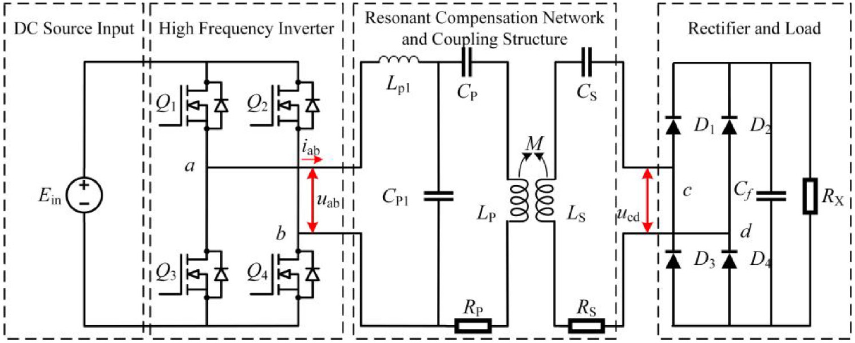
Figure 1.
Typical circuit model of WPT system.
When the influence of harmonic components is ignored, the WPT system's input voltage can be expressed in Eq. (1).
$ {U}_{ab}=\dfrac{2\sqrt{2}{E}_{in}}{\pi } $ (1) The rectifier bridge and load on the secondary side can be converted into AC equivalent load RL, which can be expressed by Eq. (2).
$ {R}_{L}=\dfrac{8{R}_{X}}{{\pi }^{2}} $ (2) Figure 2 shows the simplified circuit model of an LCC-S WPT system. Among them, Uab represents the AC voltage output by the inverter, and LP1, CP1, and CP constitute a symmetrical T-type compensation network. RL, RP, and RS correspond to the resistances of the load, transmitter coil, and receiver coil, respectively. As shown in Fig. 2, the system comprises three resonant circuits; LP1 and CP1 constitute the resonant circuit 1, the resonant angular frequency is ωP1, CP1, CP and LP constitutes the resonant circuit 2 with resonant angular frequency ωP. The third resonant circuit, composed of LS and CS, exhibits a resonant angular frequency ωS. The three frequencies are equal to the system operating frequency ω when the circuit is completely resonant, and the resonance condition is shown in Eq. (3).
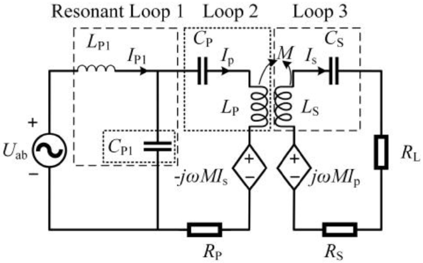
Figure 2.
Simplified structure of a LCC-S WPT system.
$ \omega =\sqrt{\dfrac{1}{{L}_{S}{C}_{S}}}=\sqrt{\dfrac{1}{{L}_{P1}{C}_{P1}}}=\sqrt{\dfrac{{C}_{P1}+{C}_{P}}{{L}_{P}{C}_{P1}{C}_{P}}} $ (3) LCC-S WPT system's impedance is analyzed using KCL and KVL laws. As shown in Eq. (4), Zs, Zref, and Zin denote the equivalent receiving impedance, reflected impedance, and input impedance of the system, respectively.
$ \begin{cases} {Z}_{S}=j\omega {L}_{S}+\dfrac{1}{j\omega {C}_{S}}+{R}_{L}+{R}_{S}\\ {Z}_{\text{ref}}=\dfrac{{\omega }^{2}{M}^{2}}{{Z}_{\text{S}}}\\ {Z}_{in}=j\omega {L}_{P1}+\dfrac{1}{j\omega {C}_{P1}+\dfrac{1}{j\omega {L}_{P}+{R}_{P}+\dfrac{1}{j\omega {C}_{P}}+\dfrac{{\left(\omega M\right)}^{2}}{{Z}_{S}}}} \end{cases} $ (4) As is shown in Eq. (5), the current corresponding to each branch of the system can be obtained:
$ \begin{cases} {\overset{\cdot }{I}}_{ab}=\dfrac{{\overset{\cdot }{U}}_{ab}}{{Z}_{in}}\\ {\overset{\cdot }{I}}_{P}=\dfrac{{\overset{\cdot }{I}}_{ab}/(j\omega {C}_{P1})}{1/\left(j\omega {C}_{P1}\right)+\left[j\omega {L}_{P}+1/\left(j\omega {C}_{P}\right)+{Z}_{ref}\right]}\\ {\overset{\cdot }{I}}_{S}=\dfrac{j\omega M{\overset{\cdot }{I}}_{p}}{{Z}_{S}} \end{cases} $ (5) The LCC-S WPT system's input power Pin, output power Pout, and transfer efficiency η are expressed by Eq. (6).
$ \begin{cases} {P}_{in}={\overset{\cdot }{U}}_{ab}{\overset{\cdot }{I}}_{ab}\\ {P}_{out}={\overset{\cdot }{I}}_{S}{}^{2}{R}_{L}\\ \eta =\dfrac{{P}_{out}}{{P}_{in}}\times 100\text{%} \end{cases} $ (6) Analysis of the circuit, based on LCC-S compensation
-
A dynamic WPT experimental platform is constructed, and a corresponding analytical model is developed to explore the influence of system parameters on output characteristics. Parameter settings for output characteristic analysis are summarized in Table 2; Uab = 20 V, the scanning range of the inverter switching frequency is (1, 150) kHz, the number of sampling points is 300, and the transmitter and receiver coils' inductance and series resistance are given. According to Eq. (3), to achieve system resonance, the compensation capacitors (CP, CS, and CP1) are calculated. In dynamic application scenarios, variations in mutual inductance and load, caused by relative positional changes, become key factors that significantly influence transfer efficiency and output power. Variation in mutual inductance can be equivalently represented by changes in coils' coupling coefficient, expressed as k
$ \in $ $ \in $ Table 2. Parameter setting for output characteristic analysis.
Parameter Value Parameter Value Parameter Value Uab 20 V LP1 2 μH f (1, 150) kHz LP 29.8 μH LS 30.2 μH k 0.1, 0.15, 0.25 RP 150.94 mΩ RS 126.08 mΩ RL 5, 10, 20 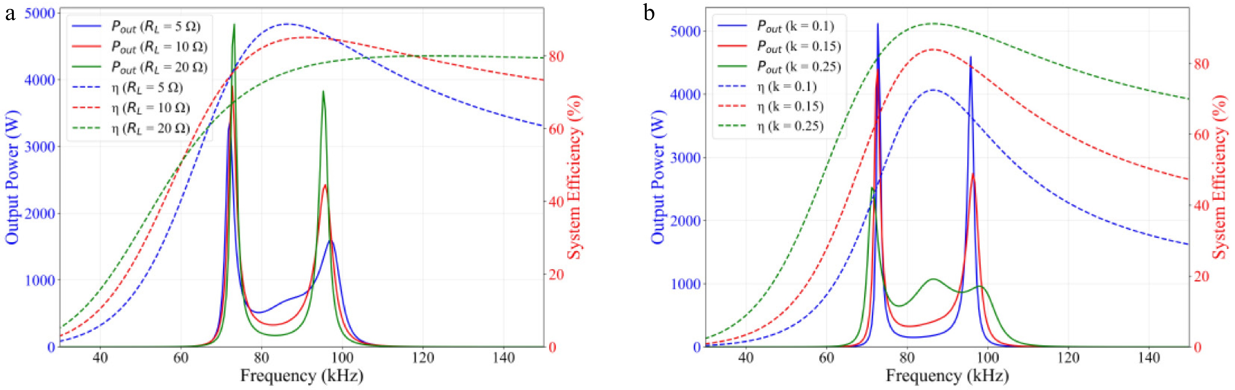
Figure 3.
System output characteristics. (a) load variation, and (b) coupling coefficient variation.
Figure 3 shows the differences in the output characteristics of the LCC-S WPT system under different load and coupling coefficient conditions. With the variation in operating frequency, a mismatch exists between the frequency corresponding to the maximum output power, and that corresponding to the maximum transfer efficiency. The transfer efficiency reaches its maximum near the resonant point, whereas the output power, due to the frequency splitting phenomenon, tends to reach higher values on both sides of the resonant frequency, rather than exactly at resonance.
Figure 3a shows that load variation from 5 to 10 and 20 Ω significantly affects both the peak locations and peak magnitudes of the output power and efficiency curves. Specifically, the output power peaks remain located near the two split frequencies, around 70–72 kHz, and 96–98 kHz, while their magnitudes increase markedly with increasing load. Meanwhile, the maximum efficiency shifts from about 86% at RL = 5 Ω to about 83% at RL = 10 Ω, and around 80% at RL = 20 Ω, and the high efficiency region becomes broader. This indicates that load variation changes the impedance matching condition of the system and thereby shifts the optimal operating range. As shown in Fig. 3b, variation in the coupling coefficient from 0.1 to 0.15 and 0.25 also has a significant influence on the system output characteristics. As the coupling coefficient increases, the maximum efficiency rises from about 72% to 84%, and then to nearly 90% near the resonant frequency of 85 kHz. At the same time, the frequency splitting behavior becomes more evident, and the deviation between the output power peak and the efficiency peak is further enlarged. In contrast, when the coupling coefficient decreases, both the output power and transfer efficiency deteriorate, and the high efficiency operating region shifts accordingly.
Therefore, parameter design based on a single operating condition or a single performance index cannot simultaneously guarantee output power and transfer efficiency under varying conditions. To overcome this challenge, a multi-objective optimization model that simultaneously considers output power, transfer efficiency, and operating condition variations is further established in this work.
-
The LCC-S compensation topology's performance is sensitive to its multiple parameters, as varying their combinations impacts both output power and transfer efficiency. Non-ideal factor fluctuations such as working environment and parameter errors will affect the system in actual operation, resulting in output power and transfer efficiency fluctuations. The design of this kind of system often needs to be combined with a multi-objective optimization algorithm.
The main influencing factors of its working environment on the system output can be divided into two types: (1) the relative positional variation between the transmitter and receiver coils during magnetic coupling; and (2) the change of load. The electrical parameters (LP, LS, RP, RS) will be determined after the winding is completed. At this time, the parameters to be designed are the primary-side series resonant compensation inductance LP1, the primary-side parallel resonant capacitance CP1, the primary-side series resonant compensation capacitance CP, and the secondary-side series resonant capacitance CS. They are written in the form of a decision vector x = [LP1, CP1, CP, CS]. The coupling coefficient k, and load resistance RL are not treated as free design variables, but as operating condition parameters that vary within prescribed ranges, s = [k, RL]
$\in $ The objective function established in this paper is shown in Eq. (7), where
$ {f}_{1}(x) $ $ {f}_{2}(\boldsymbol{x}) $ $ {f}_{1}(x) $ $ {f}_{2}(\boldsymbol{x}) $ $ \begin{cases} {f}_{1}(\boldsymbol{x})={\left[{P}_{out}\left({k}_{\max },{R}_{L\min }\right)-{P}_{\max }\right]}^{2}+{\left[{P}_{out}\left({k}_{\min },{R}_{L\max }\right)-{P}_{\min }\right]}^{2}\\ {f}_{2}(x)=\left| 1-\eta \left({k}_{\max },{R}_{L\min }\right)\right| +\left| 1-\eta \left({k}_{\min },{R}_{L\max }\right)\right| \end{cases} $ (7) The output power range (Pmin, Pmax) is determined based on the actual application scenario. Electrical constraints are added to improve device safety; the current flowing through the coil must be less than the maximum withstand current of the wire used; and the voltage at both ends of the resonant capacitor must also be less than the maximum voltage value that can be tolerated. In order to make the design reasonable, the transmitting coil requires a self-inductance LP higher than the series compensation inductance LP1. Using the specified constraints and design parameters, the system's multi-objective optimization model is expressed as shown in Eq. (8).
$ \begin{aligned}\min F(x)&=\left\{{f}_{1}(x),{f}_{2}(x)\right\}\\ & \begin{cases} {I}_{P1},{I}_{\text{P}},{I}_{\text{S}} \lt {I}_{\text{max}}\\ |{V}_{CP1}|\leq {V}_{P1,\max }\\ |{V}_{CP}|\leq {V}_{P,\max }\\ |{V}_{CS}|\leq {V}_{CS,\max }\\ {L}_{P} \gt {L}_{P1}\\ \text{Im(}{Z}_{\text{in}}\left({L}_{P1},{C}_{P1},{C}_{P},{C}_{S},{R}_{L}\right))\geq 0 \end{cases} \end{aligned} $ (8) Improved NSGA- II algorithm
-
Based on the developed circuit model, the optimization problem aims to determine the resonant compensation parameters that maximize output power and transfer efficiency while satisfying the zero-voltage-switching (ZVS) requirement. However, the maximum output power and the maximum transfer efficiency generally do not occur at the same operating point, and a manual search of efficiency curves may overlook the global optimum. Therefore, the circuit model is combined with a multi-objective optimization algorithm to obtain the compensation parameters with improved overall performance.
NSGA-II combines the elitist retention mechanism with fast non-dominated sorting, which significantly reduces the computational complexity while maintaining the diversity of the population. It is a representative method that considers both stability and efficiency in multi-objective evolutionary algorithms[22−24]. However, the standard NSGA-II still has two limitations in WPT parameter design. First, fixed crossover and mutation probabilities cannot effectively balance global exploration and local exploitation during different evolutionary stages. Second, feasible-solution search under multiple engineering constraints is not sufficiently emphasized.
In order to solve the above problems, an improved NSGA-II is adopted in this work. Adaptive simulated binary crossover (SBX) and adaptive polynomial mutation (PM) are introduced to dynamically regulate the search process, so that global exploration and local exploitation can be better balanced during evolution. In addition, constraint-aware non-dominated sorting is incorporated to explicitly prioritize feasible solutions under output, current, and ZVS constraints. Through these modifications, the proposed method improves search adaptability, feasible-solution selection capability, and robustness, for strongly coupled and multi-constraint WPT parameter optimization problems. Figure 4 is the flow chart of the improved NSGA-II, where blue represents the improved algorithm section applicable to parameter design, and orange represents the basic NSGA-II section. The detailed procedure is described as follows:
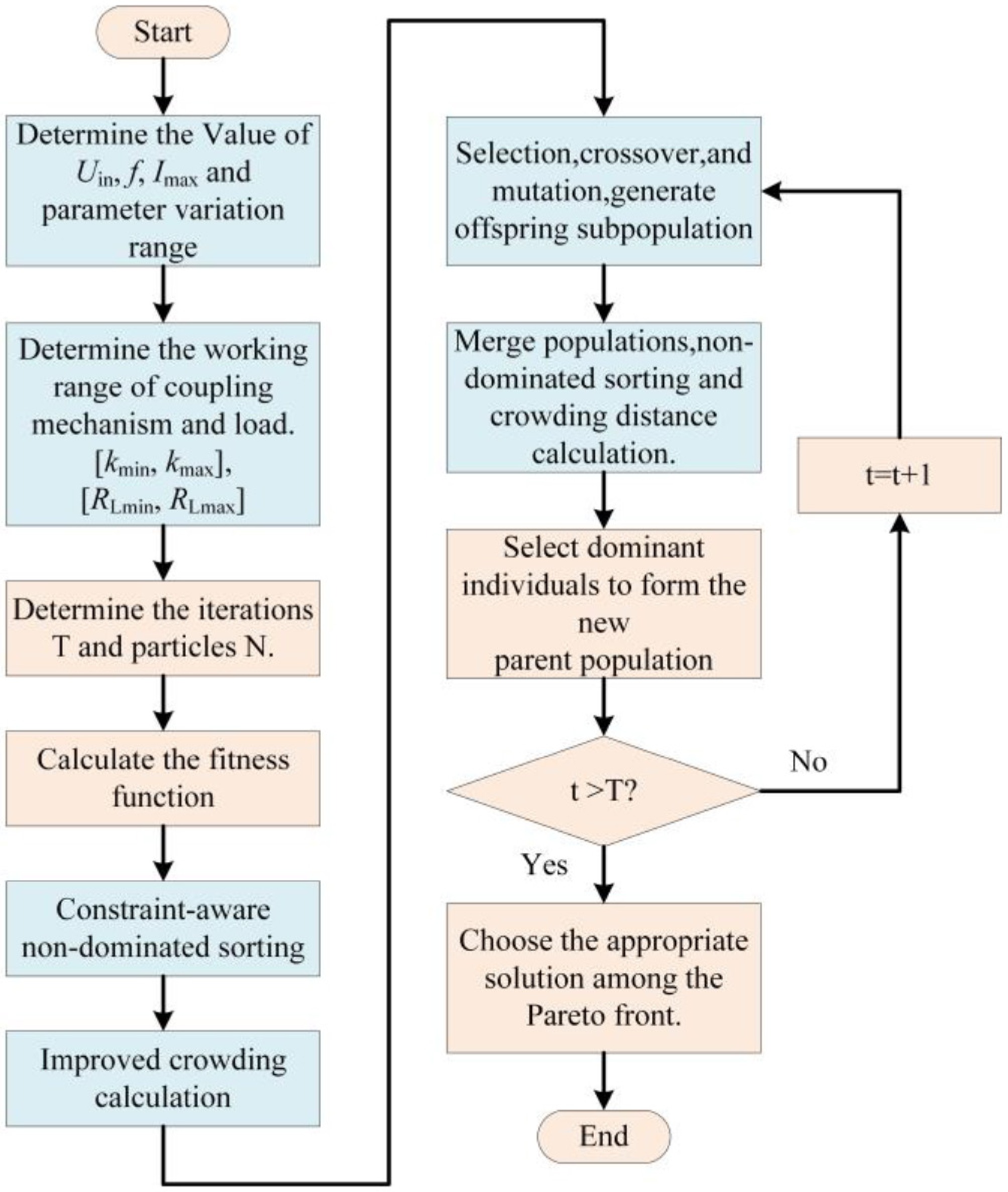
Figure 4.
Multi-objective parameter optimization process based on NSGA-II.
STEP 1: Initialize the population position P0. The algorithm begins by defining the number of particles N, the maximum iteration count T, the list of objective functions, and the corresponding parameter boundaries.
STEP 2: Objective and constraint evaluation. Each population member is assessed by calculating its objective function values and the degree to which constraints are violated. The total constraint violation degree is given by Eq. (9).
$ \text{CV}(x)=\sum \limits_{j=1}^{J}\max (0,{g}_{j}(x))+\sum \limits_{l=1}^{L}|{h}_{l}(x)| $ (9) where gj represents an inequality constraint, hl denotes an equality constraint, and J and L are the number of inequality and equality constraints, respectively.
STEP 3: Constraint non-dominated sorting. A non-dominated sorting strategy based on an ε constraint is adopted to enhance the constraint processing ability. In comparing two individuals, the assessment proceeds sequentially; first by feasibility, then by constraint violation, and last by Pareto dominance. The ε value is dynamically updated as follows.
$ \epsilon (t)=\epsilon (0)\cdot \exp \left(-\alpha \cdot \dfrac{t}{T}\right) $ (10) where ε0 represents the initial tolerance, and α is the attenuation coefficient.
STEP 4: Improved crowding-distance calculation. To improve the uniformity of Pareto front distribution, an improved crowding distance metric is employed. For the mth objective, the crowding distance of individual i is given by Eq. (11). The overall crowding distance is the sum of the distances on each target dimension, and a larger value is given to the boundary individuals to retain the extreme solution.
$ {\text{CD}}_{m}(i)=\dfrac{{f}_{m}(i+1)-{f}_{m}(i-1)}{f_{\mathrm{m}}^{\max }-f_{\mathrm{m}}^{\min }} $ (11) STEP 5: The algorithm identifies elite members through a combination of non-dominated sorting and crowding-distance evaluation. At the same time, an adaptive genetic operator is introduced to balance global exploration and local development in the evolutionary process. The crossover (pc) and mutation (pm) probabilities change linearly over the course of the current generation, and the specific formula is shown in Eq. (12).
$ \begin{cases} {p}_{c}(t)={p}_{c,\min }+({p}_{c,\max }-{p}_{c,\min })\left(1-\dfrac{t}{T}\right)\\ {p}_{m}(t)={p}_{m,\min }+({p}_{\mathrm{m},\max }-{p}_{\mathrm{m},\min })\dfrac{t}{T} \end{cases} $ (12) STEP 6: After merging the parent and offspring populations, an ε-constrained non-dominated sorting is performed again, accompanied by a refined crowding-distance calculation. Elite individuals are chosen from the first non-dominated front, and a local search strategy based on simulated annealing is applied for further refinement. The acceptance probability and temperature update formula of the new solution is shown in Eq. (13).
$ \begin{cases} {P}_{\text{accept}}=\exp \left(-\dfrac{{\Delta }f}{{T}_{\text{temp}}}\right)\\ {T}_{\text{temp}}(t+1)=\beta \cdot {T}_{\text{temp}}(t) \end{cases} $ (13) where Δf is the mass change of the solution, Ttemp is the current temperature, and β is the cooling rate.
STEP 7: At the point where the maximum iteration limit T is reached, or the change of the Pareto front is lower than the preset threshold, the algorithm is terminated. Otherwise, return to STEP 5, continue to perform elite selection, adaptive genetic operation and local search, and enter the next generation in the evolutionary process.
Algorithm optimization results
-
The electrical constraints are as follows: (1) The range of output power is (10, 50) W; (2) the lowest transfer efficiency is 80%; (3) current is less than 3.5 A; (4) the transmitting coil's self-inductance LP must exceed the series resonant inductance LP1; and (5) the realization of ZVS requires that the imaginary part of the input impedance is positive.
All computational workflows were executed on a standardized test platform (Windows 10 64-bit, Intel i5-12400F CPU @ 4.4 GHz, NVIDIA RTX 2060 Super 8 GB, 16 GB RAM) running MATLAB 2023b and Python 3.10, based on the optimization settings in the program, the improved NSGA-II uses a population size of N = 500 and a maximum number of iterations of T = 300. According to the actual runtime statistics on the standardized test platform, the average time per iteration in this stage is approximately 0.0588 s, and the total time for 300 iterations is approximately 17.63 s. The Pareto fronts generated by the improved NSGA-II are presented in Fig. 5.
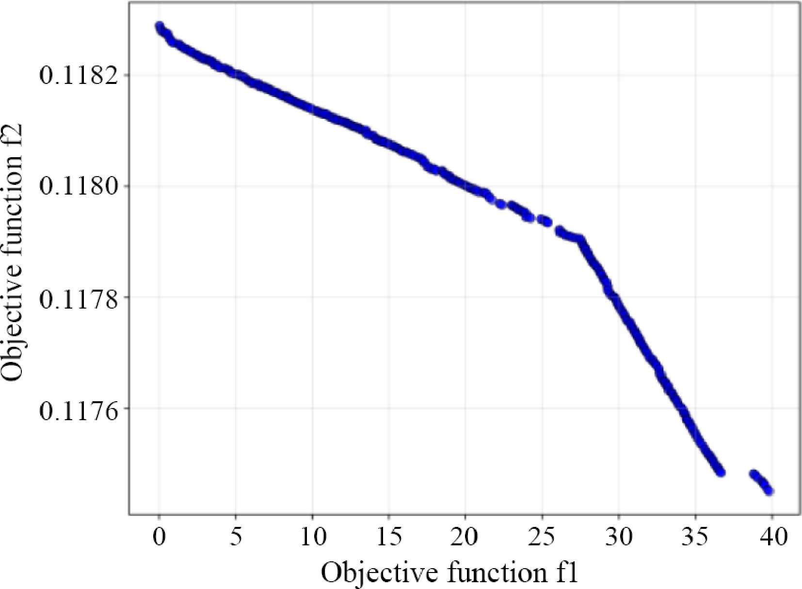
Figure 5.
Multi-objective optimization results.
Based on a comprehensive evaluation of both output power and transfer efficiency, the corresponding optimal parameter set is determined as follows: LP1 = 21.48 μH, CP1 = 82.55 nF, CP = 30.77 nF, CS = 25.19 nF, k = 0.23, and RL = 15 Ω. The theoretical output power is 30 W, and the transfer efficiency is 97.2%.
-
Figure 6 illustrates the WPT experimental platform, which includes a DC power supply, MCU controller, inverter, resonant compensation topology circuit, coupling mechanism, rectifier, and load. The platform was built to experimentally validate the effectiveness of the proposed compensation-parameter optimization method under practical operating conditions. In particular, the transmitter and receiver coils were both wound using 0.1 * 200 Litz wire. The outer dimensions of the coils are 25.1 * 18.1 cm, the inner dimensions are 16.7 * 9.8 cm, and the number of turns is 18. Under the nominal condition, the center-to-center distance between the two coils is 6 cm, corresponding to a coupling coefficient of 0.24.
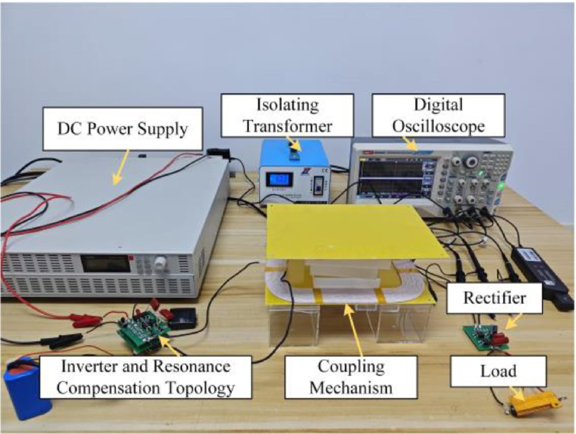
Figure 6.
Experimental setup of LCC-S WPT system.
To simplify the experimental platform and more directly evaluate the influence of the proposed compensation-parameter optimization method on system performance, no magnetic core was introduced into the coupled coils. In contrast, the series resonant inductor was wound using 0.1 * 200 Litz wire on a magnetic core, and the compensation capacitors were implemented through series-parallel combinations of discrete capacitors to obtain the required target values.
Table 3 provides the detailed values of all system components in the experiment. Set-I denotes the optimized parameter set obtained by the proposed improved NSGA-II method, and set-II denotes the comparison parameter set obtained by a conventional design approach. All parameters were measured using a VICTOR 4092D impedance analyzer.
Table 3. Experimental parameter setting.
Symbol Value Symbol Value Uab 20 V f 100 kHz LP 99.69 μH LS 100.5 μH RP 194.2 mΩ RS 225.8 mΩ LP1 (set-I) 20.9 μH LP1 (set-II) 25.24 μH CP1 (set-I) 120.5 nF CP1 (set-II) 100.5 nF CP (set-I) 32.95 nF CP (set-II) 33.3 nF CS (set-I) 24.73 nF CS (set-II) 24.73 nF RL [5, 5, 25 ] Ω k [0.12, 0.04, 0.24] When the load RL is 15 Ω, the transmitting and receiving coils are positioned with a 6 cm center-to-center spacing, the corresponding coupling coefficient is 0.23. The inverter output and load responses of the WPT system under set-I are shown in Fig. 7. Figure 7a shows the inverter output, where the peak output voltage is 21.6 V with an RMS value of 19.96 V, and the peak output current is 2.48 A with an RMS value of 1.63 A. Figure 7b shows the load's voltage and current, where the voltage value is 21.2 V, and the load current is 1.41 A. The WPT system delivers an input power of 32.45 W and an output power of 29.89 W, resulting in an energy transfer efficiency of 92.1%.
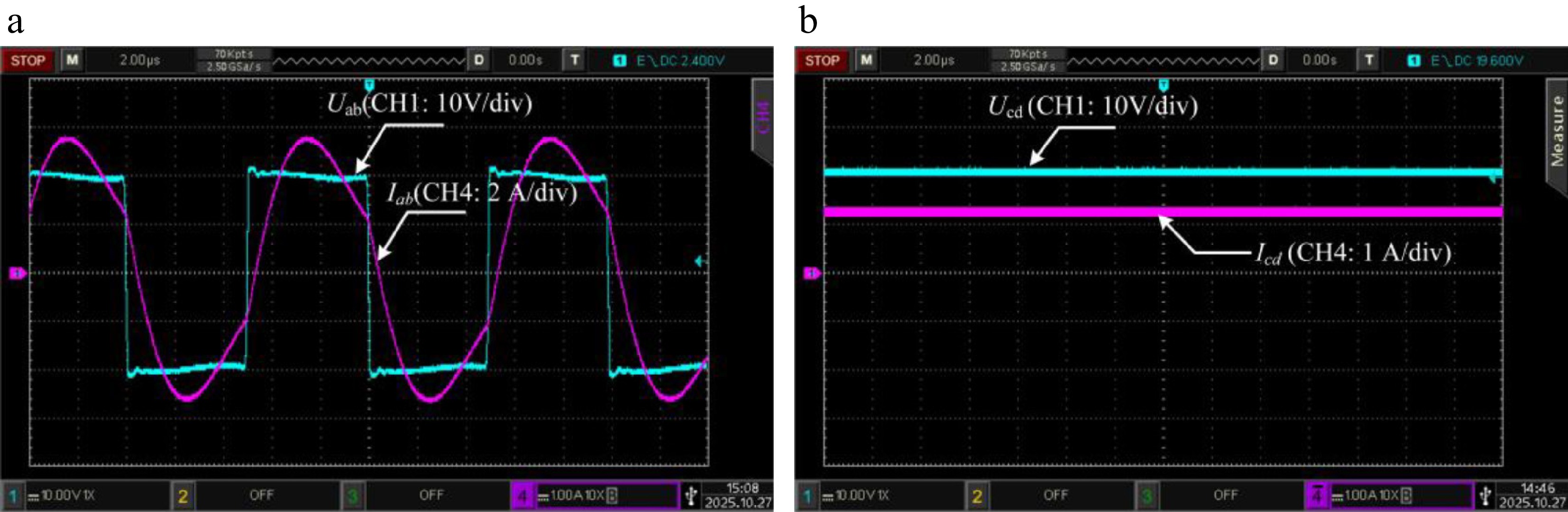
Figure 7.
Experimental results of set-I (a) inverter output, and (b) load.
To validate the effectiveness of the algorithmic optimization, the inverter output and load responses of the WPT system under set-II are presented in Fig. 8. Figure 8a is the inverter output, where the peak output voltage is 22.4 V with an RMS value of 19.95 V, and the peak output current is 2 A with an RMS value of 1.26 A. Figure 8b presents the load's voltage and current, where the voltage value is 18.4 V, and the current value is 1.2 A. Currently, the input power of the WPT system is 25.14 W, the output power is 22.08 W, and the efficiency is 87.8%. Based on the comparative analysis, the circuit parameters optimized using NSGA-II achieve higher output power and improved transfer efficiency than those obtained via the conventional design method.
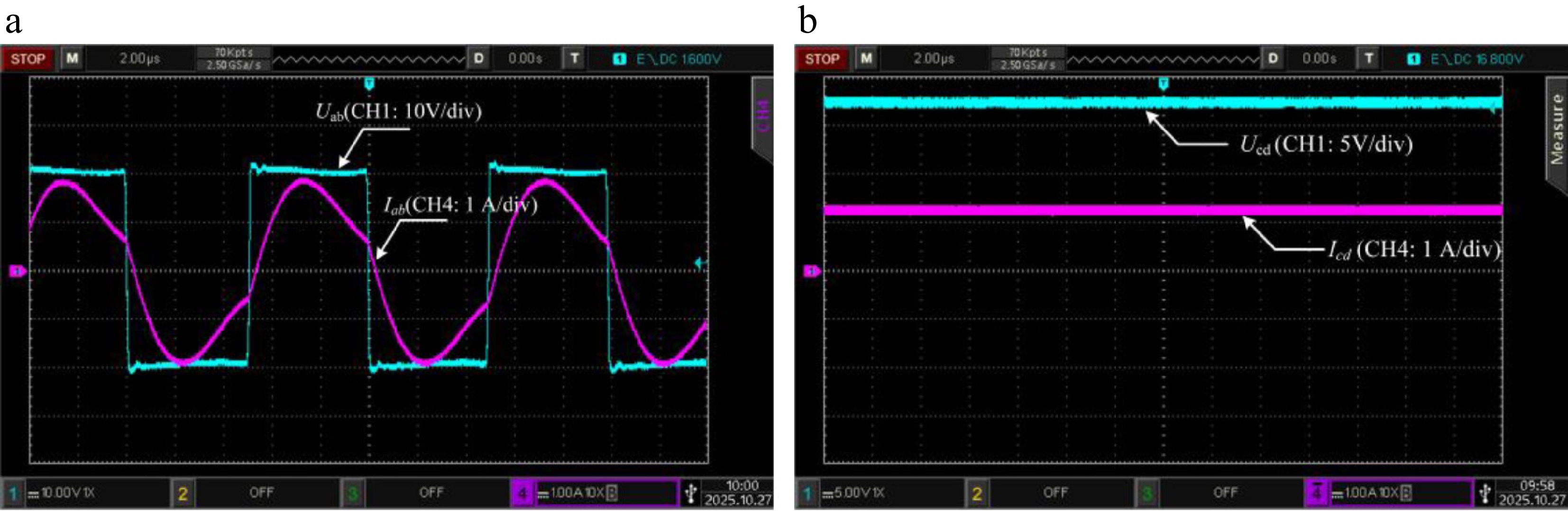
Figure 8.
Experimental results of set-II (a) inverter output, and (b) load.
The system's transfer efficiency and power output are analyzed for both the optimized (set-I) and baseline (set-II) parameter sets are shown in Fig. 9 for different coupling coefficients and load conditions. Figure 9a demonstrates that the increase in the coupling coefficient leads to a gradual rise in output power accompanied by a decrease in transfer efficiency, implying that for longer transmission distances, the system achieves higher efficiency at the expense of reduced output power. Figure 9b demonstrates that as the system load increases, output power gradually decreases, whereas efficiency increases. Across the range of coupling coefficients and load variations, the system parameter set-I optimized by NSGA-II has higher output power and transfer efficiency than set-II. Although fluctuations in output power and efficiency occur under different operating conditions, the system remains capable of adapting to these changes, ensuring that the minimum output power exceeds 10 W, and the minimum transfer efficiency remains above 80%. These results demonstrate that the system design has certain flexibility and adaptability, maintaining relatively stable performance under different working conditions.
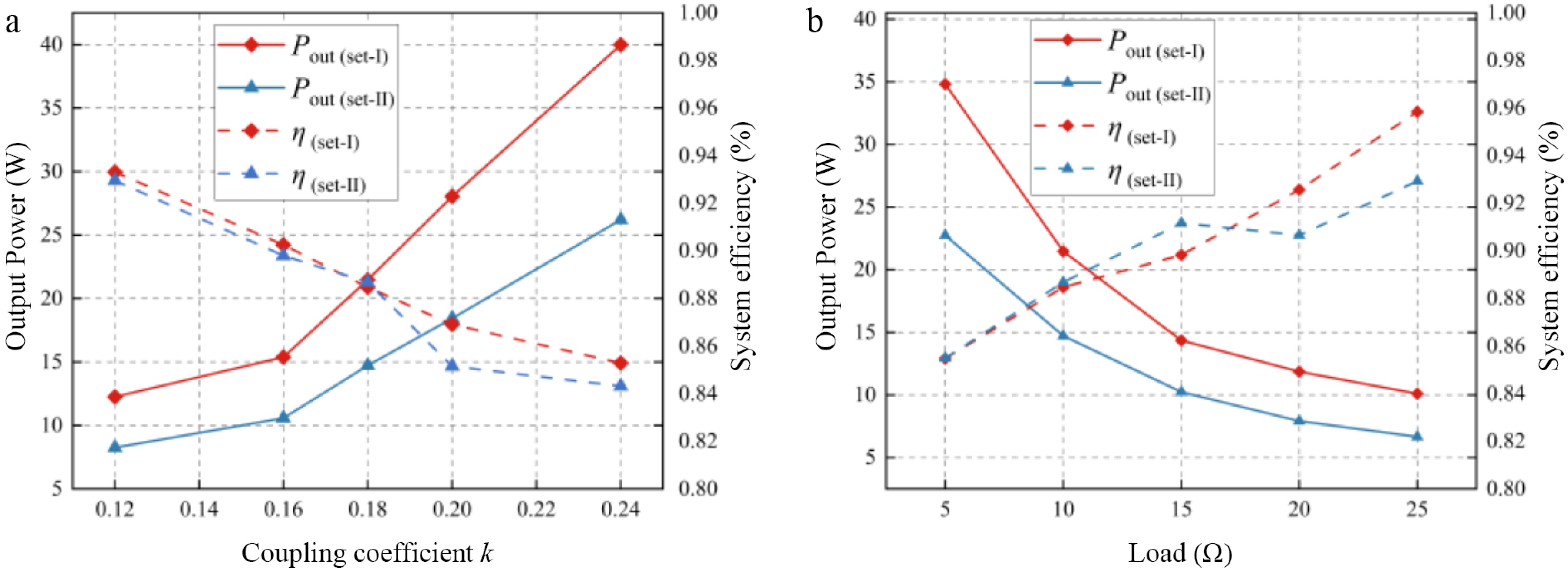
Figure 9.
Experimental results (a) coupling coefficient variation, and (b) load variation.
-
This paper proposes a multi-objective parameter optimization for the general compensation topology WPT system using an improved NSGA-II algorithm. Taking the LCC-S system as an example, by analyzing the circuit topology and output characteristics, an improved NSGA-II is employed to optimize the LCC-S compensation parameters, producing the Pareto solution set. In addition, when variations in load and coupling coefficient are incorporated into the objective function formulation, and the adaptability of the system to the change of working conditions is improved. Finally, a WPT experimental platform is established, and the proposed efficiency optimization method is used to design the parameters. The experimental evaluation shows that the optimization design method improves the system's response to changes in load and coupling coefficient while satisfying output power and transfer efficiency requirements.
-
The authors confirm their contributions to the paper as follows: study conception and design: Zhao H, Wu J, Han X, Zhang W, Liang Z; analysis and interpretation of results: Zhao H; writing – review and editing: Zhao H, Wu J. All authors reviewed the results and approved the final version of the manuscript.
-
All data analyzed during this study are included in this published article.
-
The authors declare that they have no conflict of interest.
- Copyright: © 2026 by the author(s). Published by Maximum Academic Press, Fayetteville, GA. This article is an open access article distributed under Creative Commons Attribution License (CC BY 4.0), visit https://creativecommons.org/licenses/by/4.0/.
-
About this article
Cite this article
Zhao H, Wu J, Han X, Zhang W, Liang Z. 2026. Research on efficiency improved method of WPT system based on NSGA-II parameter optimization. Wireless Power Transfer 13: e026 doi: 10.48130/wpt-0026-0017 

Research on efficiency improved method of WPT system based on NSGA-II parameter optimization
- Received: 07 January 2026
- Revised: 25 March 2026
- Accepted: 10 April 2026
- Published online: 04 September 2026
Abstract: Parameter design is crucial for dynamic wireless power transfer (WPT) systems with LCC-S compensation topology. To overcome this challenge, this article proposes a Non-dominated Sorting Genetic Algorithm II (NSGA-II) based approach for WPT system parameter optimization, aimed at improving transfer efficiency. By analyzing the established LCC-S compensation topology equivalent circuit model, key optimization variables are identified. Then, the optimization objective has been established to maximize transfer efficiency with output power requirements incorporated as constraints. In addition, the coupling coefficient and load variations are incorporated into the objective function to ensure compliance with design requirements while enhancing system stability. Experimental validation demonstrates that the proposed approach ensures constrained parameter optimization and stable operation under varying operating conditions.