











-
IMDs—such as cardiac pacemakers[1−4], neuromodulators[5,6], drug delivery systems[7,8], cochlear implants[9], deep brain stimulators[10,11], and glucose monitors[12]—have been widely adopted to perform a wide range of core functions, including physiological monitoring, biometric sensing, and targeted in vivo stimulation. To ensure the long-term, stable operation of these devices, a reliable and efficient power supply strategy is essential.
Wireless power transfer (WPT) technology offers a highly promising solution for powering IMDs[13]. In practice, WPT technology supports two distinct power supply paradigms for IMDs: (1) the battery-free operation model; and (2) the rechargeable-battery-based operation model. The former is typically employed for direct physiological sensing (e.g., non-real-time glucose monitoring) where the implanted receiver is activated only when an external transmitter is brought into proximity, thereby facilitating on-demand data collection. The latter, in contrast, relies on periodic wireless recharging of an internal battery, thereby supporting the long-term operation of the IMD. Together, these two paradigms collectively highlight the adaptability of WPT technology in addressing the practical demands of implantable systems.
Near-field magnetic resonance wireless power transfer (NF-MR-WPT) technology represents a superior strategy for powering IMDs. Compared to other WPT approaches—such as capacitive coupling, microwave radiation, optical transmission, and ultrasonic waves—NF-MR-WPT offers distinct advantages, including efficient short-range transmission, scalable power levels, high AC-to-AC power transfer efficiency, and excellent bio-compatibility[14,15]. Beyond these core merits, NF-MR-WPT operating in the megahertz (MHz) range provides the following three key benefits: (1) enhanced power transfer efficiency attributed to the improved quality factors of the transmitter and receiver coils[16]; (2) miniaturized and lightweight coil designs enabled by the higher operating frequency[17,18]; and (3) improved tolerance to coil misalignment[19,20]. Consequently, these attributes position MHz-band NF-MR-WPT as a preferable power supply solution.
However, a critical challenge currently constrains the practical application of NF-MR-WPT technology in IMDs. Specifically, this limitation stems from insufficient integration—particularly, the low modular integration of the receiver subsystem, which is responsible for harvesting wireless power to support the IMD's intended operational functions. In conventional implementations[21−23], receiver subsystems uniformly employ a standardized discrete modular architecture, typically comprising three independent functional units: a power pickup coil, a resonant compensation network, and a rectification module. While this architecture offers broad compatibility across NF-MR-WPT receiver subsystems, it fails to address the unique operational constraints of the in vivo environment, which necessitate stringent compactness and a lightweight design to mitigate patient discomfort. The traditional discrete architecture increases the receiver subsystem's overall volume and structural complexity, constraints that directly contradict the aforementioned in vivo design requirements. Therefore, achieving high-level system integration of the receiver subsystem has emerged as a critical technical challenge.
In this paper, we propose a multi-functional toroidal rectifier that integrates three core functions—resonance compensation, rectification, and filtering—into a single-turn power pick-up coil. Structurally, the device incorporates two independent thin-film circuits that generate induced voltages across them during operation. In turn, this setup enables highly efficient AC-to-DC power conversion using a compact set of components: two compensation capacitors, two rectifying diodes, and one filtering capacitor. The experimental results indicate that, at an input power of 873 mW and an implantation depth of 10 mm, the proposed multi-functional toroidal rectifier can achieve a 49.98% AC-DC efficiency, thus confirming the effectiveness of this integrated architecture.
-
The structure of the toroidal rectifier is visualized in Fig. 1a. It is composed of two symmetrical thin-film copper foils, two rectifier diodes, two compensation capacitors, and a filter capacitor. These two copper foils are obtained by splitting a single-turn coil in half. For the diode configuration, the cathodes of the two diodes D1 and D2 are connected to a common conductor, while their respective anodes are linked to a separate conductor. To suppress leakage inductance and improve power transfer efficiency, two compensation capacitors Cs, are utilized. Notably, each parallel diode-capacitor assembly is placed at the split position of the copper foils. To fulfill the filtering function, a filter capacitor C is employed.
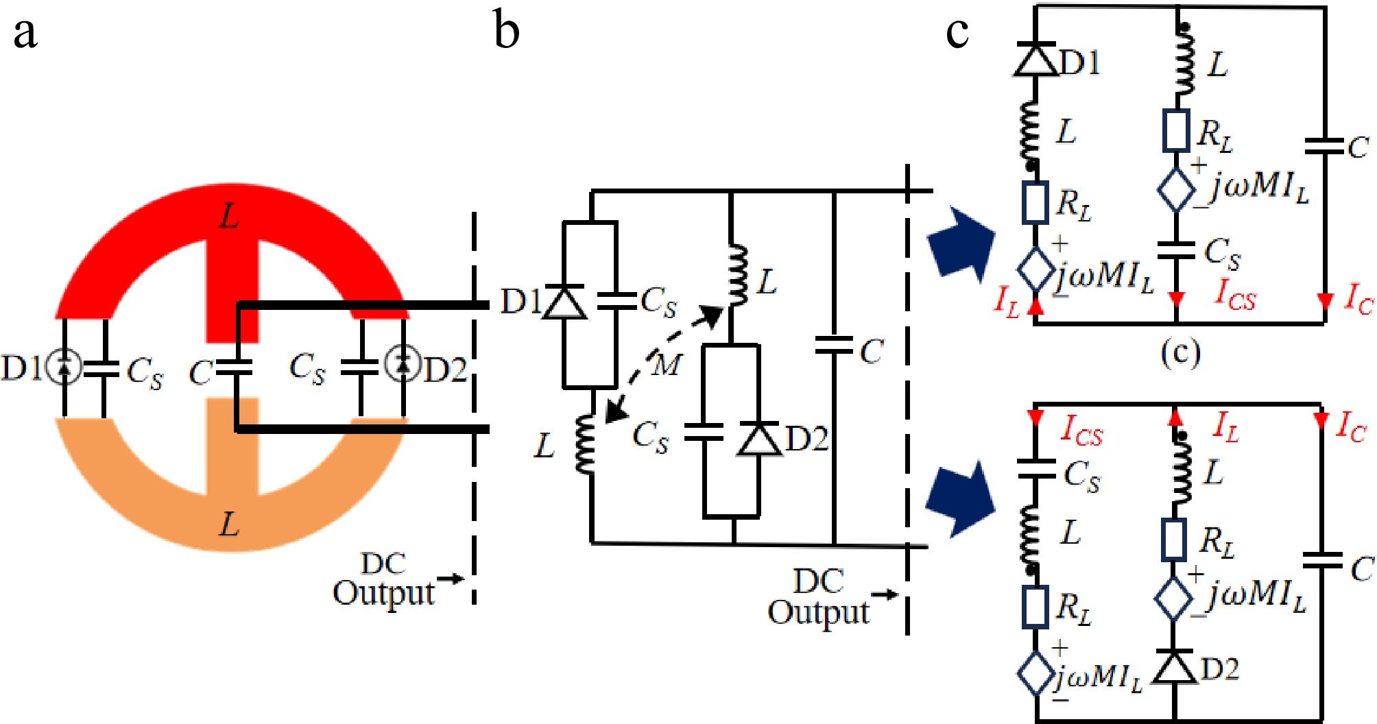
Figure 1.
The toroidal rectifier and simplified equivalent circuit models. (a) Physical structure diagram of the rectifier toroidal. (b) Equivalent circuit model of a receiver rectifier toroidal. (c) Equivalent circuit when D1 is on, and D2 is off. (d) Equivalent circuit when D1 is off, and D2 is on.
The equivalent circuit of the toroidal rectifier is presented in Fig. 1b, where L denotes the self-inductance of each copper foil, and M represents the mutual inductance between two foils. In the following, the operating principle of the toroidal rectifier is elaborated. During each half-cycle of operation, one diode is conducting, equivalently short-circuiting its parallel capacitor Cs, while the other diode remains cut off, creating an open circuit in its respective branch. For example, when D1 is on-state, and D2 is cut off, the corresponding equivalent circuit is shown in Fig. 1d.
Hence, both AC voltage and current can be output to the load, which is connected in parallel with the filter capacitor.
In the receiver design, the toroidal coil[24] is an ideal choice for the IPT system receiver due to its simple structure, unidirectional magnetic flux, low flux leakage, and reduced energy loss. To further analyze its characteristics, both the physical model and the equivalent circuit model of the toroidal coil are established, as shown in Fig. 2. The equivalent circuit of this single-port toroidal coil consists of an inductance and an equivalent series resistance.
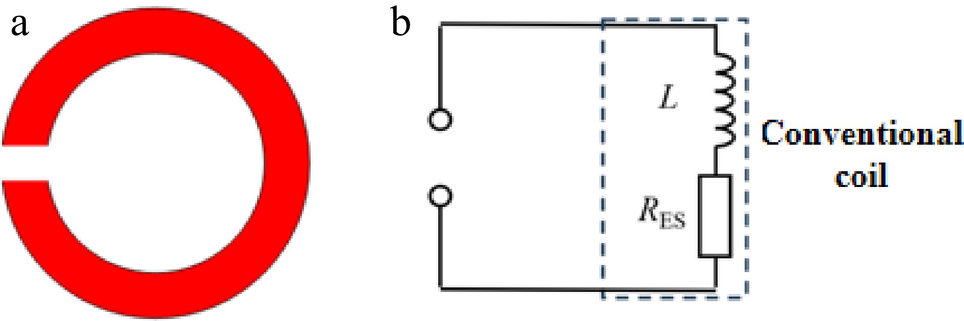
Figure 2.
Single-port toroidal coil. (a) Schematic of the physical model. (b) Schematic of the equivalent circuit.
To ensure that the proposed rectifier coil can directly output DC power, the key lies in the use of two independent conductors that are electrically isolated from each other. Furthermore, when excited by an alternating magnetic field, the two conductors share the same electrical status, which requires the structure to exhibit good symmetry. Therefore, the single-port toroidal coil is split into two symmetrical parts, as illustrated in Fig. 3a. Through this conceptual division, the corresponding equivalent circuit can be represented as two branches, as shown in Fig. 3b. In this circuit, M denotes the mutual inductance between the two inductors.
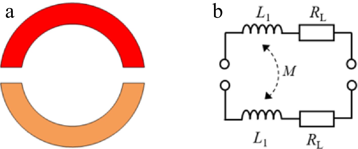
Figure 3.
Dual-port toroidal coil. (a) Schematic of the physical model. (b) Schematic of the equivalent circuit.
To address the limitations of conventional rectifiers, this paper proposes a non-self-resonant rectifier coil that combines the advantages of both bridge rectifiers and full-wave rectifiers. The proposed coil makes full use of the entire coil for rectification in each half-cycle, with only one diode conducting per half-cycle. This reduces the number of lumped components, thereby lowering losses and improving efficiency. Based on this operating principle, two diodes are required to conduct alternately during the positive and negative half-cycles. The specific connection is as follows: the cathodes of the two diodes are jointly connected to the same conductor of the single-turn coil, while their anodes are connected to the other conductor, as shown in Fig. 4a. To provide a clearer illustration of its equivalent circuit, the corresponding circuit model is presented in Fig. 4b.
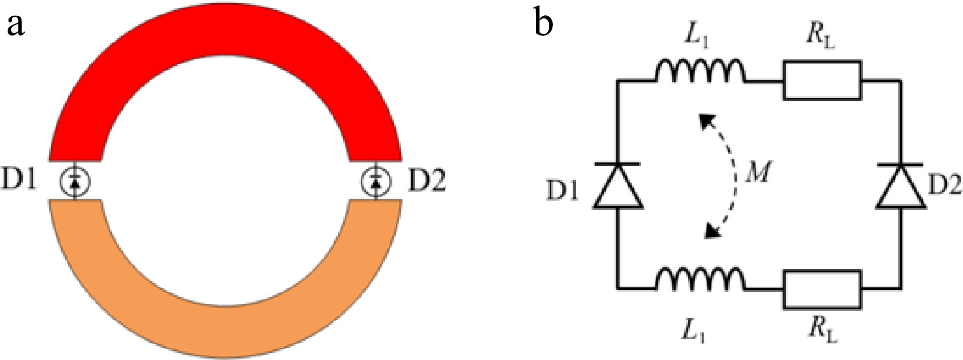
Figure 4.
Rectifier toroidal coil. (a) Schematic of the physical model. (b) Schematic of the equivalent circuit.
To mitigate the issue of leakage inductance, lumped capacitors are connected either in series or in parallel with the coil. In this work, based on the rectifier toroidal coil, two lumped compensation capacitors are introduced. The specific connection method is illustrated in Fig. 5a, b, which presents a simplified equivalent circuit model of the capacitor-compensated rectifier toroidal coil. This model consists of two rectifier diodes, two inductors, two equivalent series resistors, and two lumped compensation capacitors. In this configuration, the rectifier diodes are responsible for converting AC to DC, while the lumped compensation capacitors serve to compensate for the leakage inductance of the coil.
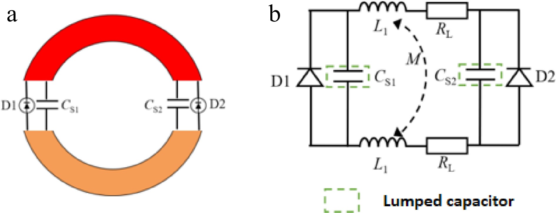
Figure 5.
Capacitor-compensated rectifier toroidal coil. (a) Schematic of the physical model. (b) Schematic of the equivalent circuit.
The DC output of the non-self-resonant rectifier coil is obtained through the voltage difference between the two conductors. To ensure a smooth and continuous output waveform, a filter capacitor C is placed between the two conductors, thereby enabling a stable DC power supply at the port. As shown in Fig. 6a, the non-self-resonant rectifier coil consists of two symmetrical thin-film copper foils, two rectifier diodes, two compensation capacitors, and one filter capacitor. Considering the specific application scenario where the non-self-resonant rectifier coil is to be implanted into human tissue, lumped capacitors are preferred over parasitic capacitance, as they confine the electric field within the capacitors themselves, thereby reducing electromagnetic interference with the surrounding tissue.
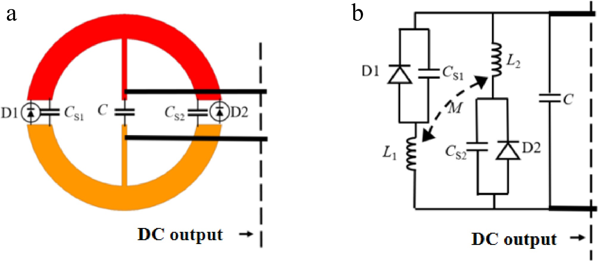
Figure 6.
Non-self-resonant rectifier toroidal. (a) Schematic of the physical model. (b) Schematic of the equivalent circuit.
The simplified equivalent circuit model of the non-self-resonant rectifier coil is shown in Fig. 6b. It consists of two rectifier diodes
$ {\text{D}}_{1} $ $ {\text{D}}_{2} $ $ {L}_{1} $ $ {L}_{2} $ $ {C}_{\text{S1}} $ $ {C}_{\text{S2}} $ $ {L}_{1}={L}_{2} $ $ {C}_{\text{S1}}={C}_{\text{S2}} $ $ {L}_{1} $ $ {L}_{2} $ Additionally, considering that the non-self-resonant rectifier coil is intended for implantation in the body, the copper foils are encapsulated with polyimide (PI) to prevent direct contact between the conductors and body tissue. Polyimide has been demonstrated to be a biocompatible material[25]. The non-self-resonant rectifier coil without lumped components is shown in Fig. 7.
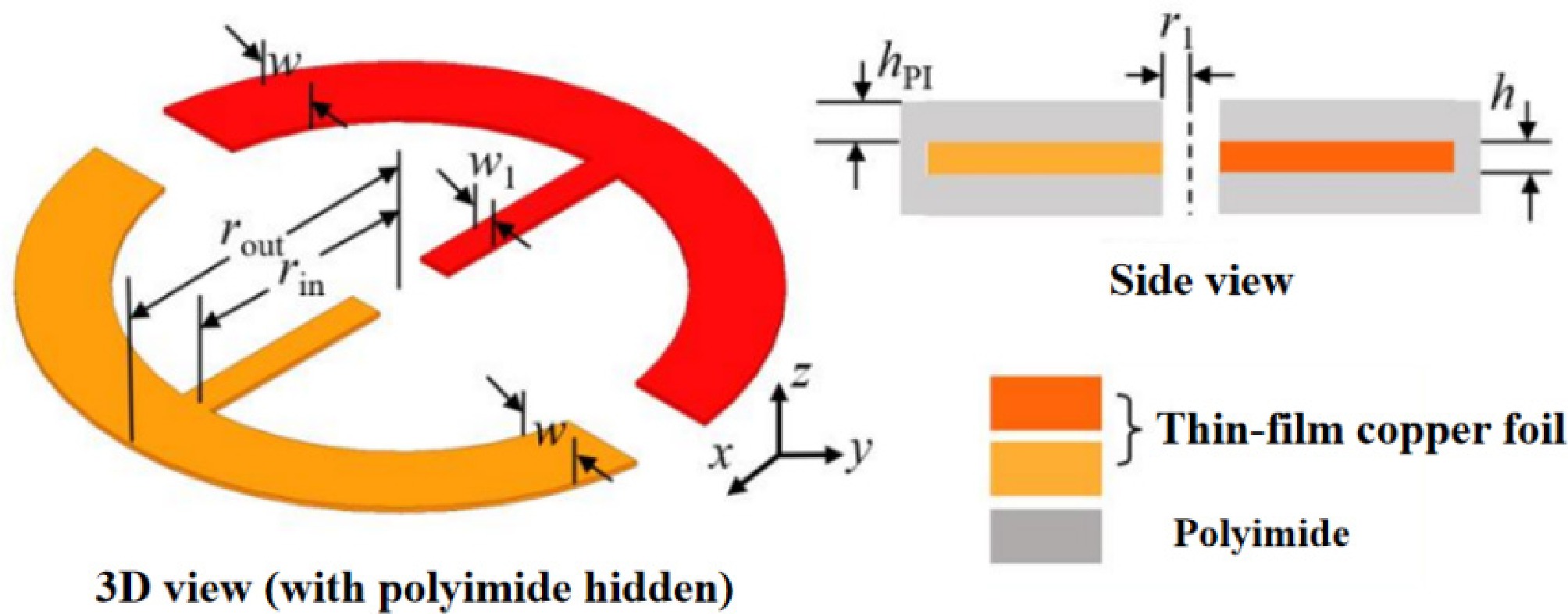
Figure 7.
Schematic of the non-self-resonant rectifier toroidal coil (lumped elements not shown).
The parameters of the non-self-resonant rectifier coil are presented in Table 1, from which the volume of the coil is calculated to be 31.73 mm3. Additionally, polyimide has a relative permittivity
$ {\varepsilon }_{r} $ $ \tan \delta $ $ {\mu }_{r} $ Table 1. Parameters of the non-self-resonant rectifier toroidal coil.
$ {\mathrm{r}}_{\text{out}} $(mm) $ {\mathrm{r}}_{\text{in}} $(mm) $ {\mathrm{r}}_{1} $(mm) $ \mathrm{W} $(mm) $ {\mathrm{W}}_{1} $(mm) $ \mathrm{h} $(mm) $ {\mathrm{h}}_{\text{PI}} $(mm) 10 5 0.267 5 0.5 0.035 0.05 During each half-cycle of operation of the non-self-resonant rectifier coil, one diode is in a conducting state, effectively creating a short circuit in the circuit, while the other diode remains in a non-conducting state, effectively creating an open circuit in the circuit. This operating condition is illustrated in Fig. 8a, and its equivalent circuit is presented in Fig. 8b.
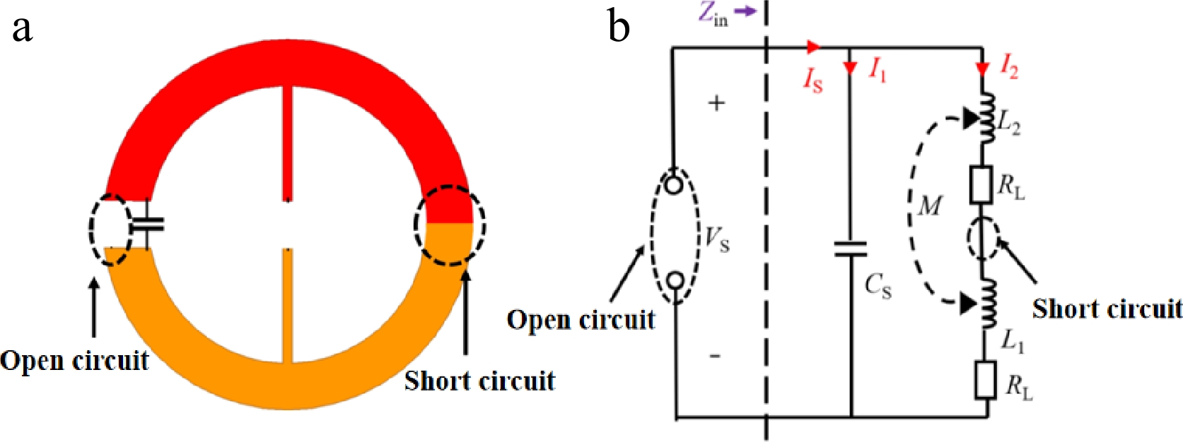
Figure 8.
Toroidal coil. (a) Schematic of the physical model. (b) Schematic of the equivalent circuit.
Using Kirchhoff's voltage and current laws, a formula applicable to both positive and negative half-cycles is derived as follows:
$ {I}_{\text{S}}={I}_{1}+{I}_{2} $ (1) $ -j\dfrac{1}{\mathit{\omega}C_{\text{S}}}I_1=j{{{\omega}}}(L_1+L_2+2M)I_2+2R_{\text{L}}I_2 $ (2) $ {V}_{\text{S}}=-j\dfrac{1}{\omega {C}_{\text{S}}}{I}_{1} $ (3) The input impedance (
$ {Z}_{\text{in}} $ $ {Z}_{\text{in}}=\dfrac{{V}_{\text{S}}}{{I}_{\text{S}}}={R}_{\text{in}}+j{X}_{\text{in}} $ (4) Among them, the resonance condition is derived based on the condition
$ {X}_{\text{in}}=0 $ $ 2\omega(L+M)=1/\omega C_{\mathrm{S}} $ (5) In each half-cycle of the non-self-resonant rectifier coil, only one diode is in the conducting state. When diode D2 is conducting, and D1 is cut off, the corresponding circuit topology is shown in Fig. 9a; conversely, when diode D1 is conducting, and D2 is cut off, the circuit topology is presented in Fig. 9b. These two topologies together constitute the complete operating states of the non-self-resonant rectifier coil over a full cycle.
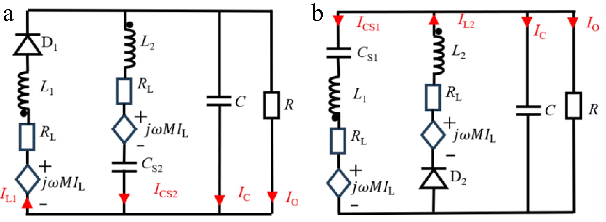
Figure 9.
Two operating topologies of the non-self-resonant rectifier toroidal coil. (a) D2 is conducting, and D1 is cut off. (b) D1 is conducting, and D2 is cut off.
Furthermore, based on these two topological configurations, the current relationships among the various components in the circuit can be deduced. When diode D2 is conducting, and D1 is cut off, corresponding to the condition illustrated in Fig. 9a, the current flowing through the load R satisfies:
$ {I}_{\text{O}}={I}_{\text{L2}}-{I}_{CS1}-{I}_{C} $ (6) When diode
$ {\text{D}}_{1} $ $ {\text{D}}_{2} $ $ {I}_{\text{O}}={I}_{\text{L2}}-{I}_{CS1}-{I}_{C} $ (7) $ {\boldsymbol{\eta }}_{\boldsymbol{A}\boldsymbol{C}-\boldsymbol{D}\boldsymbol{C}} $ of WPT employing toroidal rectifier
-
Where
$ {\eta }_{AC-DC} $ The structure of the WPT system employing the toroidal rectifier as the receiver is shown in Fig. 10a. In this setup, an AC source is connected to the transmitter, while a DC load R is connected to the toroidal rectifier, with the separation distance between the transmitter and receiver denoted as d. The equivalent circuit is shown in Fig. 10b. In this circuit, Lt and CS denote the inductance and capacitor of the transmitter, respectively. M′ and M″ represent the mutual inductance between Lt and L1, and between Lt and L2, with the condition that
$ {M}{'}={M}{''} $ 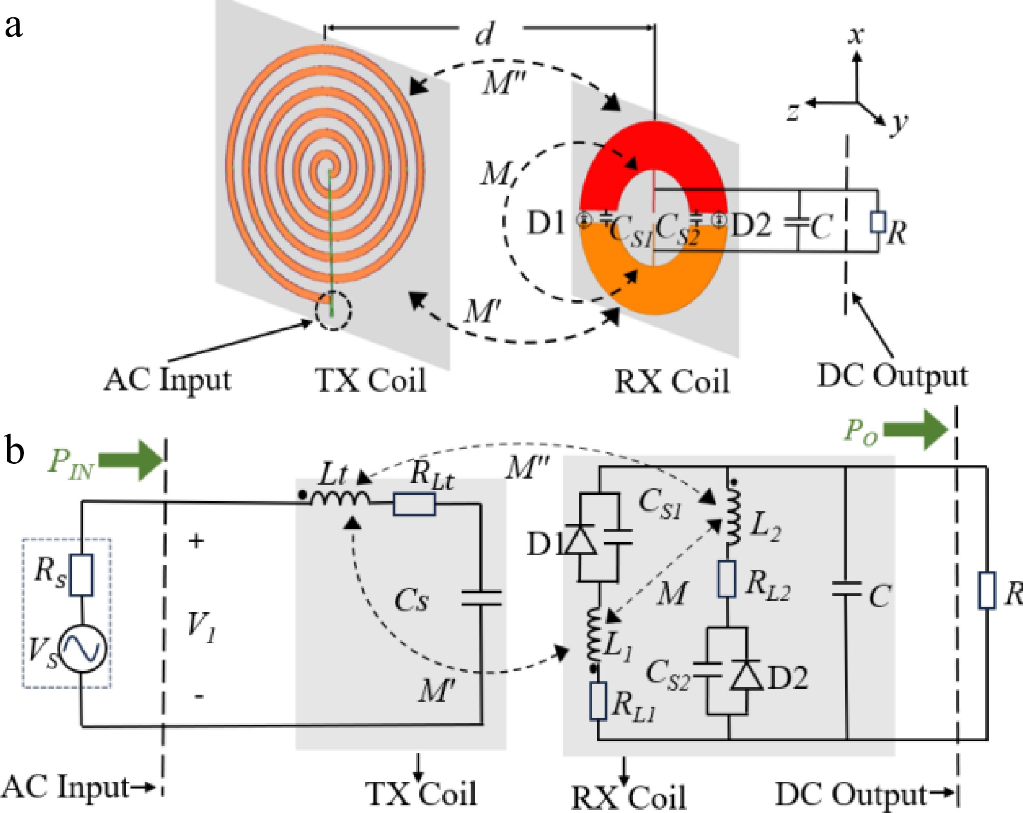
Figure 10.
(a) Structure, and (b) equivalent circuit of a toroidal rectifier in WPT.
The corresponding equivalent circuit is illustrated in Fig. 10b, and
$ {\eta }_{AC-DC} $ $ \eta_{AC-DC}=\dfrac{P_{\mathrm{O}}}{P\mathrm{_{IN}}} $ (8) where, an AC power
$ {P}_{\text{IN}} $ $ {P}_{\text{O}} $ SAR (specific absorption rate) analysis
-
In the design of IMDs, the specific absorption rate (SAR) has become an indispensable consideration, crucial for ensuring human safety. Ensuring that SAR remains within safe limits is a critical step in protecting patient health and minimizing potential risks.
The IEEE standards C95.1-1999 and 95.1-2005 establish maximum allowable SAR values of less than 1.6 W/kg (averaged over 1 g of tissue) and 2.0 W/kg (averaged over 10 g of tissue), respectively[26,27]. The SAR is defined as:
$ SAR=\dfrac{\sigma {\left| E\right| }^{2}}{\rho } $ (9) where,
$ \sigma $ $ \rho $ SAR simulations are conducted through the full-wave software Ansys HFSS. A three-layer model, as shown in Fig. 11, is employed to represent human tissues, consisting of skin, fat, and muscle. The relevant electromagnetic parameters of human tissues are presented in Table 2, including relative permittivity, dielectric loss tangent, conductivity, and density. The external transmitter is positioned at a distance of 1 mm from the skin surface, while the toroidal rectifier is implanted within the muscle layer at a depth
$ {d}_{p} $ 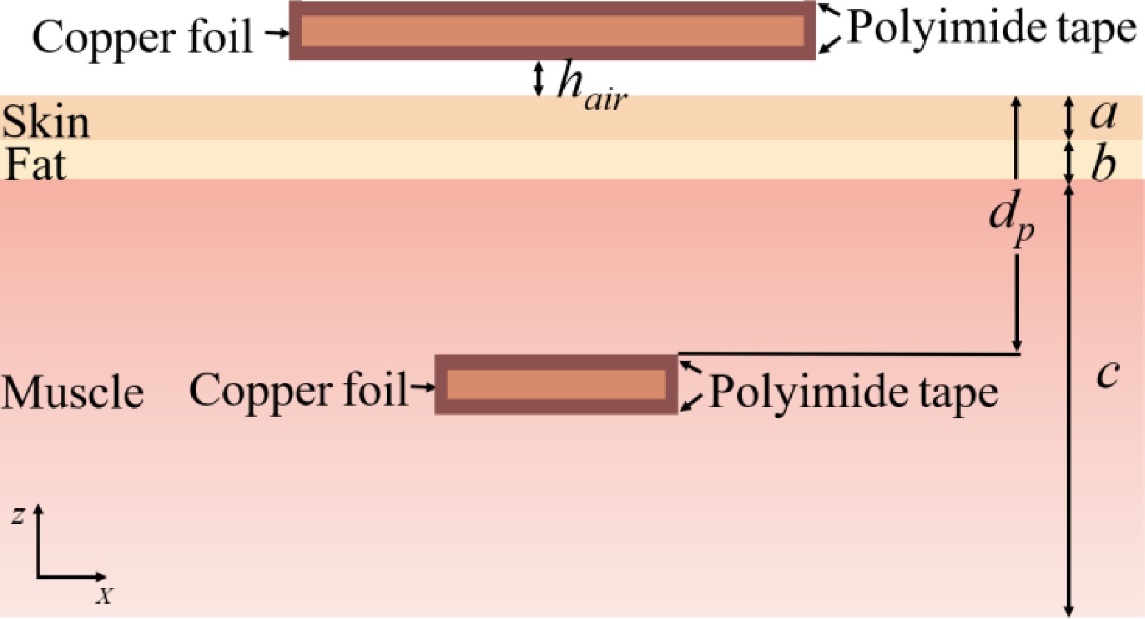
Figure 11.
Overall structure of the three-tissue-layer model of skin-fat-muscle with thicknesses of 2, 2, and 6 mm.
Table 2. Electromagnetic parameters of human tissues.
Relative
permittivity $ {\varepsilon }_{r} $Dielectric loss
tangentConductivity Density
(kg/m3)Skin 122.91 1.3655 0.37982 1,109 Fat 7.286 2.0703 0.034136 911 Muscle 82.115 3.6046 0.66986 1,090 Figure 12a, b shows the 1-g and 10-g average SAR distributions in the XZ plane, respectively, under the conditions of a 40.68 MHz operation frequency, and an input power of 1 W. The peak averaged SARs are 4.84 W/kg and 2.25 W/kg, respectively. Based on these results, the maximum safe input power for the external transmitting coil is determined to be 330 mW and 889 mW for the 1-g and 10-g averaging criteria, respectively.
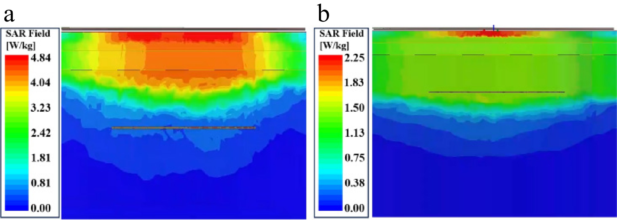
Figure 12.
Distribution of the average SAR in the human body at 40.68 MHz with a 1 W input power and a 10 mm implant depth. (a) 1 g-avg SAR, and (b) 10 g-avg SAR distributions.
-
To validate the efficacy of this design, the toroidal rectifier prototype is presented in Fig. 13a on the left. It measures 5 mm in width, 20 mm in outer diameter, and 0.1 mm in thickness, featuring a small size and flexibility. To minimize conductive losses between the copper and the surrounding tissue, the prototype is wrapped in polyimide tape. It is integrated with a ZLLS410 rectifier diode, a 0.135 uF filtering capacitor, and a 1.2 nF capacitor for resonance at 40.68 MHz. The utilized transmitting coil, in Fig. 13a on the right, consists of six turns, with a diameter of 32 mm and a thickness of 0.21 mm.
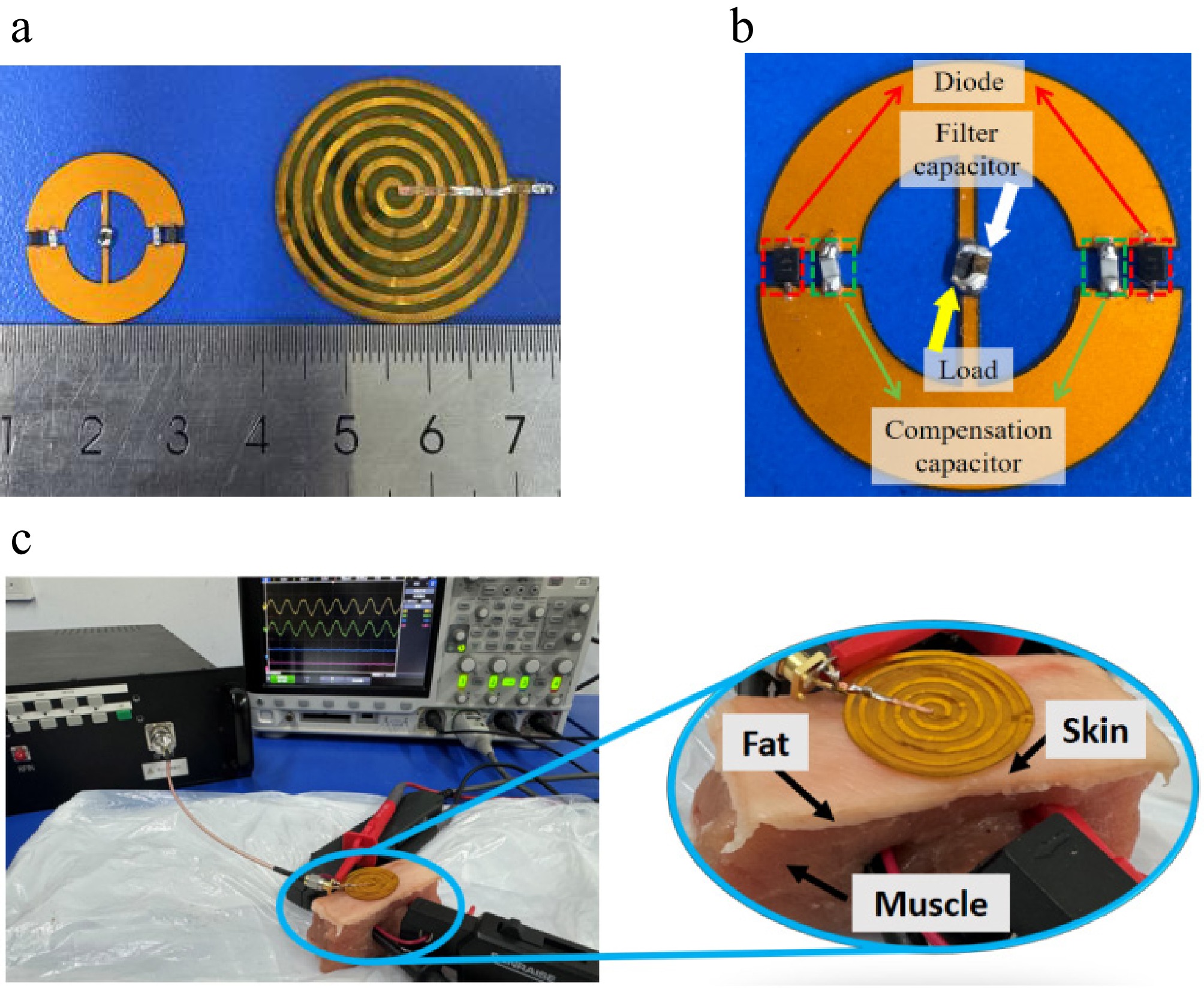
Figure 13.
Experimental prototype and setup. (a) Top view of the toroidal rectifier on the left and transmitting coil on the right. (b) Detailed view of the toroidal rectifier. (c) The experimental setup employing the pork tissue to simulate the three-layer human tissue.
The specific experimental setup is illustrated in Fig. 13c. The toroidal rectifier coil is embedded within the muscle tissue, while the transmitter is placed on the skin surface, maintaining a 1 mm air gap between the two coils. The transmitter is driven by a QX-ASA100M signal source, operating at the designed resonant frequency. The toroidal rectifier coil is connected to a DC load to evaluate its rectification performance. Voltage and current waveforms are monitored using a Keysight DSOX3024T oscilloscope. Both the AC input signals to the transmitter and the DC output from the toroidal rectifier are recorded to calculate system efficiency and characterize power delivery.
The experiment simulates
$ {\eta }_{AC-DC} $ $ {\eta }_{AC-DC} $ $ {\eta }_{AC-DC} $ $ {\eta }_{AC-DC} $ $ {\eta }_{AC-DC} $ $ {\eta }_{AC-DC} $ 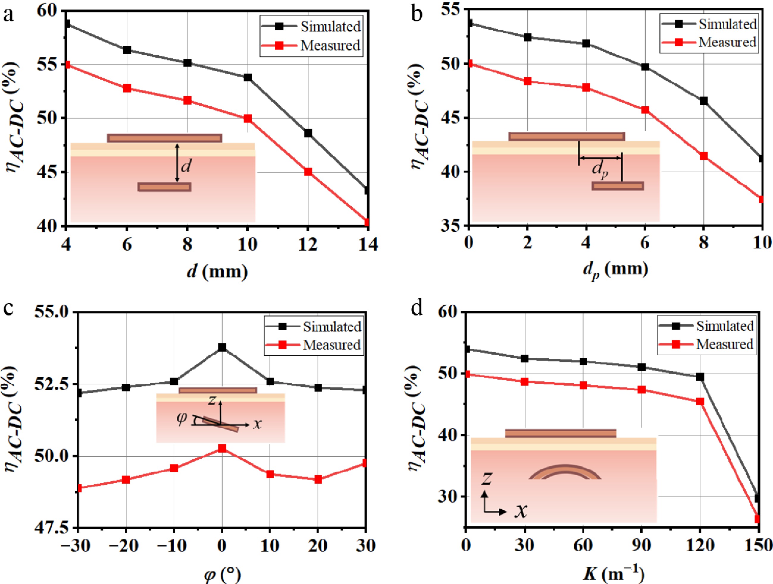
Figure 14.
Simulated and measured $ {\eta }_{AC-DC} $ under varying conditions: (a) d, (b) dp, (c) φ, and (d) K.
The measured waveforms of the proposed toroidal rectifier are presented in Fig. 15. In this figure, CH1 and CH2 represent the input voltage and input current, respectively, and CH3 represents the RMS output voltage across the load at the receiving end.
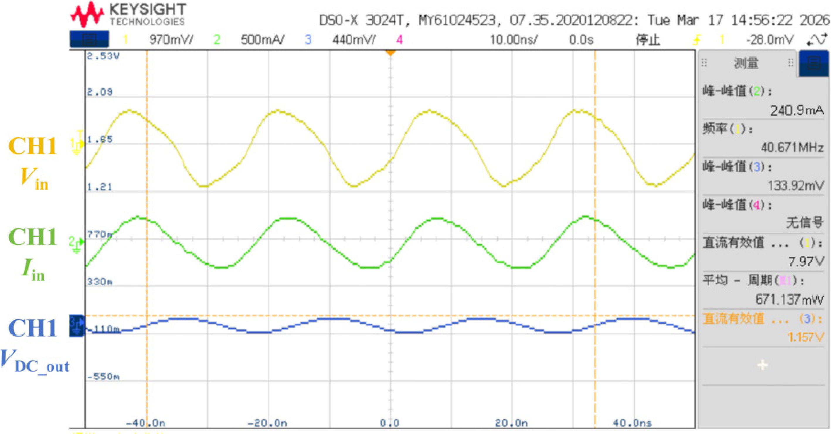
Figure 15.
Experimental waveform diagram at an implantation depth of d = 10 mm.
To validate the rectification performance of the proposed toroidal rectifier under an input power of approximately 671 mW, we conducted measurements under the following experimental conditions: input power PIN = 671.137 mW, operating frequency
$ f $ Based on the waveform measurements, the average input power is calculated to be PIN = 671.137 mW, and the DC output voltage is
$ {V}_{\text{out,DC}} $ $ P_{\text{out}}=\dfrac{V_{\text{out,DC}}^2}{R_{\mathrm{L}}}=\dfrac{1.157^2}{4}=334.7\; \text{mW} $ (10) The AC-DC conversion efficiency of the system is shown as:
$ {\eta }_{AC-DC}=\dfrac{{P}_{\text{out}}}{{P}_{\text{in}}}=\dfrac{334.7}{671.1}=49.86\text{%} $ (11) Table 3 provides a comparison of the measurements obtained from the proposed design with those reported in other studies. As shown, the WPT-based toroidal rectifier exhibits relatively high
$ {\eta }_{AC-DC} $ Table 3. Comparison of the proposed toroidal rectifier with other coils.
Ref. $ f $ (MHz) Volume (mm3) Implant depth (mm) $ {\eta }_{AC-AC} $ $ {\eta }_{AC-DC} $ Input power (mW) SAR (W/kg) Max allowable received AC power (mW) 1 g-avg/10 g-avg [28] 39.86 249.5 10 47.2 NA 245/676 6.54/2.96 115/319 [29] 403 975.4 6 42.4 NA NA/159 NA/1.05 NA/67 [30] 13.56 1472 11 17 NA NA/ NA NA/ NA NA/NA Pro. 40.68 65.97+ 10 NA 49.98 330/889 4.84/2.25 165/444 -
In this paper, a novel toroidal rectifier with both coupling and rectification functions is proposed. The coil can achieve 49.98% AC-DC efficiency at an implantation depth of 10 mm, offering biosafety and sufficient power for IMD applications.
This research was funded by the National Natural Science Foundation of China (Grant No. 52207214).
-
The authors confirm contribution to the paper as follows: study conception and design: Yi Z, Liang Y, Qin Y; data collection: Yi Z, Liang Y, Xu Z; analysis and interpretation of results: Liang Y, Li M; draft manuscript preparation: Yi Z, Liang Y. All authors reviewed the results and approved the final version of the manuscript.
-
The datasets generated during and/or analyzed in the current study are available from the corresponding author on reasonable request.
-
The authors declare that they have no conflict of interest, and manuscript is approved by all authors for publication.
- Copyright: © 2026 by the author(s). Published by Maximum Academic Press, Fayetteville, GA. This article is an open access article distributed under Creative Commons Attribution License (CC BY 4.0), visit https://creativecommons.org/licenses/by/4.0/.
-
About this article
Cite this article
Yi Z, Liang Y, Qin Y, Xu Z, Li M. 2026. Compact wireless power transfer for implantable medical devices with flexibility toroidal rectifier. Wireless Power Transfer 13: e027 doi: 10.48130/wpt-0026-0019 

Compact wireless power transfer for implantable medical devices with flexibility toroidal rectifier
- Received: 15 January 2026
- Revised: 30 March 2026
- Accepted: 25 May 2026
- Published online: 16 September 2026
Abstract: Compact, multi-functional receiving coils are essential for implantable medical devices (IMDs). In this paper, we propose an integrated toroidal rectifier that consolidates coupling, rectification, and filtering functions into a single power pick-up coil. This design employs only a minimal component set: two thin-film circuits, two compensation capacitors, two rectifier diodes, and one filter capacitor. In contrast to the traditional strategies that employ three independent modules on the receiver side—a power pick-up coil, a rectifier, and a filter—the proposed multi-functional toroidal rectifier can directly output DC power, making it highly suitable for implantation in the human body. Its operating principle is briefly illustrated in this study. Experimental results demonstrate that an AC-DC power transfer efficiency of 49.98% is achieved at an operating frequency of 40.68 MHz. Moreover, with a 1 W system power input, the specific absorption rates are 4.84 W/kg for a 1-g tissue mass and 2.25 W/kg for a 10-g tissue mass, both well within the regulatory safety limit. This highly integrated architecture resolves the trade-off between receiver-side compactness and functional completeness in IMDs, laying a technical foundation for next-generation implantable systems.