


-
In the petroleum and chemical industries, pool fires caused by the leak of combustible fluids are frequent accidents. The heat radiation generated by pool fires seriously threatens the surrounding environment and facility safety. A significant quantity of thermal energy is released as radiation during the pool fire accident, which will cause direct thermal damage to personnel. The view factor (also known as the shape factor or configuration factor) is one of the key variables influencing radiant heat intensity. It considers the relative position and geometric shape between the radiation source and the receiving surface, which is used to calculate the radiant heat exchange between them. In the fire safety field, accurate view factor research is crucial for determining fire separation distance and evaluating fire thermal radiation.
Scholars have continuously improved and developed theoretical models for estimating the view factors. Beyler[1] pointed out that the variations in the predicted versus measured heat fluxes vary considerably between methods when studying multiple predictive models. He provided the applicable scope of these methods. McGrattan et al.[2] proposed that the view factor F can be calculated by assuming the fire perimeter to be made up of circular arcs or straight lines. Bosch & Weterings[3] derived a method for calculating view factors based on the Mudan model, where the value of the intermediate variable a depends on whether the target is located within the flame shadow. Wang et al.[4] found that the overall view factor is always less than 1. It decreases sharply with the increase of the ratio of distance to radius, while it increases slowly with the increase of the flame aspect ratio.
Furthermore, as a design standard for fire separation distance in the petroleum and chemical industries, the latest 'General Code for Fire Protection of Buildings and Constructions' (GB 55037-2022)[5] stipulates the fire separation distance for industrial and civil buildings. The fire separation distances should be determined based on the building's usage characteristics, height, fire resistance rating, and fire hazard level. The fire separation distance between buildings should ensure that the radiant heat intensity received by any side of a building's external wall from an adjacent building's fire is below the critical ignition heat intensity.
Therefore, this paper focuses on the pool fire scenario and comprehensively analyzes the influence of different view factors on the distribution of heat radiation. Analyzing the fire separation distances between the actual storage tank and the workshops provides theoretical support for the evaluation of the quantitative fire separation distances. It provides references for plant layout, safety and fire protection design, fire risk assessment, and emergency response in the petroleum and chemical industries.
-
This paper adopts a cylindrical pool fire model to simulate actual fire scenarios in systematic research of pool fire hazards. Its main characteristic parameters include the combustible liquid's mass-loss rate, liquid pool radius, flame height, flame tilt angle, total radiant heat flux, surface average radiant heat flux, and the received radiant heat flux at the target.
Mass burning rate per unit area[6]
-
When the boiling point of a combustible liquid exceeds the ambient temperature, the mass burning rate is given by the expression (1):
$ m = \dfrac{{0.001{H_{\text{c}}}}}{{{C_p}\left( {{T_b} - {T_0}} \right) + {H_{V ap}}}} $ (1) When the boiling point of a combustible liquid below the ambient temperature, the mass burning rate is given by the expression (2):
$ m = \dfrac{{0.001{H_c}}}{{{H_{V ap}}}} $ (2) Where: m is the mass burning rate per unit area of the combustible liquid surface, kg/(m2·s); Cp is the specific heat capacity at constant pressure of the combustible liquid, kJ/(kg·K); Hc is the heat of combustion of the combustible liquid, kJ/kg; Hvap is the heat of vaporization of the combustible liquid, kJ/kg; Tb is the atmospheric pressure boiling point of combustible liquid, K; T0 is the ambient temperature, K.
Liquid pool radius
-
According to the total amount of the leaked liquid and the characteristics of the ground, the maximum possible liquid pool area can be calculated using expression (3)[7]. At the same time, the radius of the leak liquid pool is given by expression (4):
$ S = \dfrac{W}{{\left( {{H_{\min }}\rho } \right)}} $ (3) $ R = \sqrt {\dfrac{S}{\pi }} $ (4) Where: S is the area of the liquid pool, m2; R is the radius of the liquid pool, m; W is the mass of the leak liquid, kg; ρ is the density of the liquid, kg/m3; Hmin is the minimum thickness of the liquid layer, m.
Flame height
-
To simplify liquid combustion and the resulting flame characteristics. It is assumed that the liquid pool is circular, the flame is cylindrical, and its diameter is the same as that of the liquid pool. Thomas's empirical formula gives the flame height of pool fire under two conditions: wind-free and wind-affected[8, 9].
1) Flame height of the pool fire under wind-free conditions is given by expression (5):
$ H = 84R{\left[ {\dfrac{m}{{{\rho _a}\sqrt {2gR} }}} \right]^{0.61}} $ (5) Where: H is the flame height, m; ρa is the air density, kg/m3; g is the gravity acceleration.
2) Flame height of the pool fire under wind-affected conditions is given by expression (6):
$ H = 110R{\left( {\dfrac{m}{{{\rho _a}\sqrt {2gR} }}} \right)^{0.67}}{\left( {{\omega ^*}} \right)^{ - 0.21}} $ (6) The non-dimensional wind velocity is given by expression (7):
$ {\omega ^*} = \dfrac{{{\omega _w}}}{{{{\left( {{{2gmR} \mathord{\left/ {\vphantom {{2gmR} {{\rho _v}}}} \right. } {{\rho _v}}}} \right)}^{\frac{1}{3}}}}} $ (7) Where: ωw is the wind speed at a height of 10 m, m/s; according to statistics, the annual average wind speed in the region where the selected enterprise is located is 3.2 m/s; ρv is the fuel vapor density, kg/m3.
Flame tilt angle
-
The flame tilt angle is given by expression (8). It is calculated using the relation expression proposed by Pritchard & Binding[10]:
$ \dfrac{{\tan \theta }}{{\cos \theta }} = 0.666{\left[ {\dfrac{{{\omega _w}}}{{2gR}}} \right]^{\frac{1}{3}}}{\left( {\dfrac{{2{\omega _w}R}}{\upsilon }} \right)^{0.117}} $ (8) Where: θ is the flame tilt angle, °; υ is the dynamic viscosity of air, m2·s.
Total radiant heat flux[11]
-
$ Q = \dfrac{{\left( {\pi {R^2} + 2\pi RH} \right){H_c} \times m \times \eta }}{{72{m^{0.61}} + 1}} $ (9) Where: Q is the total radiant heat flux, kW; η is the efficiency factor, take 0.24.
Surface average radiant heat flux[11]
-
$ E = \dfrac{{2mR{H_c}f}}{{2R + 4H}} $ (10) Where: E is the surface average radiant heat flux, kW/m2; f is the thermal radiation coefficient, take 0.1−0.3.
Point source model
-
$ I = \dfrac{{Q{t_c}}}{{4\pi {L^2}}} $ (11) Where: I is the received radiant heat flux at the target, kW/m2;tc is the conduction coefficient, take 1; L is the distance between the target and the pool's center, m.
Radiant heat intensity prediction models
-
The radiant heat intensity at a certain distance from the ground around the pool fire is given by expression (12)[12, 13]:
$ q = EF\tau $ (12) Where: q is the radiant heat flux received from the target position at x away from the center of the liquid pool,kW/m2; F is the view factor, τ is the atmospheric transmission coefficient, which can be taken as
$ \tau = 1 - 0.058\ln x $ View factor
Mudan model
-
Bosch derived a set of view factor calculation methods based on the Mudan model. It is given by expressions (13)[3, 14]:
$ F = \sqrt {F_V^2 + F_H^2} $ (13) Where: FV is the geometric view factor of the target in the vertical direction; FH is the geometric view factor of the target in the horizontal direction.
Calculate the view factor at a point x from the center of the liquid pool. When the target is located on the downwind side of the flame, θ should be taken as a positive value. Conversely, if the target is located on the upwind side, θ should be taken as a negative value.
$ \begin{split} \pi {F_V} =\;& - E{\tan ^{ - 1}}G + E\left[ {\dfrac{{{a^2} + {{(b + 1)}^2} - 2b(1 + a\sin \theta )}}{{AB}}} \right]{\tan ^{ - 1}}\left( {\dfrac{{AG}}{B}} \right) + \\ & \dfrac{{\cos \theta }}{C}\left[ {{{\tan }^{ - 1}}\left( {\dfrac{{ab - {H^2}\sin \theta }}{{HC}}} \right) + {{\tan }^{ - 1}}\left( {\dfrac{{H\sin \theta }}{C}} \right)} \right] \end{split} $ (14) $ \begin{split} \pi {F_H} =\;& {\tan ^{ - 1}}\left( {\dfrac{1}{G}} \right) + \dfrac{{\sin \theta }}{C}\left[ {{\tan }^{ - 1}}\left( {\dfrac{{ab - {H^2}\sin \theta }}{{HC}}} \right) \right.+\\&\left. {{\tan }^{ - 1}}\left( {\dfrac{{H\sin \theta }}{C}} \right) \right]-\\ & \left[ {\dfrac{{{a^2} + {{(b + 1)}^2} - 2(b + 1 + ab\sin \theta )}}{{AB}}} \right]{\tan ^{ - 1}}\left( {\dfrac{{AG}}{B}} \right) \end{split} $ (15) Where,
$ a = \dfrac{h}{R} $ When the target is outside the shadow of the flame, i.e., x ≥ R + Hsinθ, h = H. When the target is within the shadow of the flame, i.e., R < x < R + Hsinθ , h = (x-R)/sinθ. Where: x is the horizontal distance between the centerline of the flame and the ground target (personnel or equipment), m.
$ b = \dfrac{x}{R} $ $ A = \sqrt {{a^2} + {{(b + 1)}^2} - 2a(b + 1)\sin \theta } $ $ B = \sqrt {{a^2} + {{(b - 1)}^2} - 2a(b - 1)\sin \theta } $ $ C = \sqrt {1 + ({b^2} - 1){{\cos }^2}\theta } $ $ G = \sqrt {{{(b - 1)} / {(b + 1)}}} $ $ {E = {{(a\cos \theta )} /{(b - a\sin \theta )}}\quad \quad \quad \quad\quad \;\ }$ $ H = \sqrt {{b^2} - 1} $ Where a, b, A, B, C, G, E, H are intermediate variables.
Rai-Kalelkar model
-
The view factor F is given by expression (16). The calculation method was proposed by Rai & Kalelkar[4, 15]:
$ F = \sqrt {{V^2} + {{\left( {\dfrac{{A - B}}{\pi }} \right)}^2}} $ (16) Where
$\begin{array}{*{20}{l}}& a = \dfrac{{{h^2} + {s^2} + 1}}{{2s}},\; b = \dfrac{{1 + {s^2}}}{{2s}},\; K = {\tan ^{ - 1}}\left[ {\sqrt {\dfrac{{s - 1}}{{s + 1}}} } \right]\\& J = \left[ {\dfrac{a}{{\sqrt {{a^2} - 1} }}} \right]{\tan ^{ - 1}}\sqrt {\dfrac{{(a + 1)(s - 1)}}{{(a - 1)(s + 1)}}}\\& B = \left[ {\dfrac{{a - 1}}{{s\sqrt {{a^2} - 1} }}} \right]{\tan ^{ - 1}}\sqrt {\dfrac{{(a + 1)(s - 1)}}{{(a - 1)(s + 1)}}}\\& A = \left[ {\dfrac{{b - 1}}{{s\sqrt {{b^2} - 1} }}} \right]{\tan ^{ - 1}}\sqrt {\dfrac{{(b + 1)(s - 1)}}{{(b - 1)(s + 1)}}}\\& V = \dfrac{{{{\tan }^{ - 1}}\left[ {\dfrac{h}{{\sqrt {{s^2} - 1} }}} \right] + h(J - K)}}{{\pi s}}\end{array}$ Where: s is the ratio of the distance between the center of the liquid pool and the target to the liquid pool radius R; h is the ratio of the flame height H to the liquid pool radius R; a, b, K, J, B, A, V are intermediate variables.
Mudan-Sparrow model
-
Mudan employed a contour integral approach developed by Sparrow to determine closed-form equations for view factors from a tilted cylinder[1, 3]. The view factor F is given by expression (17):
$ F = \sqrt {F_{1 \to 2,V}^2 + F_{1 \to 2,H}^2} $ (17) $ \begin{split} \pi {F_{1 \to 2,V}} =\;& \dfrac{{a\cos \theta }}{{b - a\sin \theta }}\dfrac{{{a^2} + {{(b + 1)}^2} - 2b(1 + a\sin \theta )}}{{\sqrt {AB} }}{\tan ^{ - 1}}\sqrt {\dfrac{A}{B}} \sqrt {\dfrac{{b - 1}}{{b + 1}}} + \\ & \dfrac{{\cos \theta }}{{\sqrt C }} \times \left[ {{{\tan }^{ - 1}}\left( {\dfrac{{ab - ({b^2} - 1)\sin \theta }}{{\sqrt {{b^2} - 1} \sqrt C }}} \right) + {{\tan }^{ - 1}}\left( {\dfrac{{({b^2} - 1)\sin \theta }}{{\sqrt {{b^2} - 1} \sqrt C }}} \right)} \right] - \\ & \dfrac{{a\cos \theta }}{{(b - a\sin \theta )}}{\tan ^{ - 1}}\sqrt {\dfrac{{b - 1}}{{b + 1}}} \\[-15pt] \end{split} $ (18) $ \begin{split} \pi {F_{1 \to 2,H}} =\;& {\tan ^{ - 1}}\sqrt {\dfrac{{b + 1}}{{b - 1}}} - \dfrac{{{a^2} + {{(b + 1)}^2} - 2(b + 1 + ab\sin \theta )}}{{\sqrt {AB} }}\times\\& {\tan ^{ - 1}}\sqrt {\dfrac{A}{B}}\times \sqrt {\dfrac{{b - 1}}{{b + 1}}} + \dfrac{{\sin \theta }}{{\sqrt C }} \times \Bigg[ {{\tan }^{ - 1}}\left( {\dfrac{{ab - ({b^2} - 1)\sin \theta }}{{\sqrt {{b^2} - 1} \sqrt C }}} \right) +\\& {{\tan }^{ - 1}}\left( \dfrac{{\sqrt {({b^2} - 1)} \sin \theta }}{{\sqrt C }} \right) \Bigg]\\[-15pt] \end{split} $ (19) Where,
$ a = \dfrac{H}{R},\;b = \dfrac{x}{R} ,\; A = {a^2} + {(b + 1)^2} - 2a(b + 1)\sin \theta,\; B = {a^2} + $ $ {(b - 1)^2} - 2a(b - 1)\sin \theta,\; C = 1 + ({b^2} - 1){\cos ^2}\theta $ Where a, b, A, B, C are intermediate variables.
When comparing the three view factor models, it can be observed that the Mudan and Mudan-Sparrow models need to calculate the flame tilt angle θ. In the Mudan model, the intermediate variable (a) depends on whether the target is located within the flame shadow. In contrast, the Rai-Kalelkar model can calculate the view factor when the liquid pool radius and flame height are given. It is relatively simple compared with the other two methods.
-
In the petroleum and chemical industries, workshop storage tanks are generally located on the periphery of the workshop. It is used for temporary storage during production processes. Therefore, there may be more operation errors, resulting in a relatively high frequency of accidents. When the storage tank leaks and causes a fire, it can cause serious harm to personnel and facilities in the surrounding area. The workshop personnel density is relatively high. In an emergency event, a confined workspace may hinder the rapid evacuation of personnel, leading to more casualties. Therefore, the workshop storage tank is chosen to represent the assumption of the pool fire scenario.
The research object is the intermediate storage tank of 1,2-dichloroethane in the ethrel production process of a certain pesticide manufacturing chemical company. 1,2-dichloroethane, a First-B class combustible liquid, is one of the hazardous chemicals used in this operation. The storage tank is located at the periphery of the workshop.
Pool fire scenario assumption: 1,2-dichloroethane storage tank, the operating pressure is atmospheric pressure; the operating temperature is room temperature; the tank is a vertical tank; the tank specifications is Φ1,200 × 5,500; the capacity is 6 m³; the actual storage capacity is 4.2 m3 (5,293 kg). Under these conditions, the physicochemical properties of 1,2-dichloroethane are as follows:
Density: 1,260 kg/m3;
Boiling point: 356.65 K;
Specific heat of air at constant pressure: 1.3058 kJ/(kg·K);
Heat of combustion: 12,578.95 kJ/kg;
Heat of vaporization: 361.6557 kJ/kg.
Leak source strength calculation
-
The boiling point of 1,2-dichloroethane at atmospheric pressure is 83.7 °C, flash evaporation does not occur during leakage. Therefore, the leakage rate is calculated using the Bernoulli expression (20)[16]:
$ {Q_{m1}} = \rho A{C_0}\sqrt {2\left( {\dfrac{{p - {p_0}}}{\rho } + g{h_L}} \right)} $ (20) Where: Qm1 is the mass flow rate, kg/s; P is the liquid pressure in the storage tank, Pa, the production unit for atmospheric pressure tanks, take 101,325 Pa; P0 is the ambient atmosphere pressure, Pa, take 101,325 Pa; C0 is the leakage coefficient of the liquid, which depends on the shape of the hole and the flow state, take 0.65; A is the area of the leakage hole, m2; hL is the height of the liquid above the leak hole, considering the liquid discharge from the bottom of the storage tank, take 3.85 m.
The actual setup of production facilities is as follows: After 30 s of combustible liquid leakage, the combustible gas leakage alarm meter will sound, and the DCS (Distributed Control System) in the control cabin will display the leak from the storage tank. The combustible gas leakage alarm meter is chained to the tank's emergency shutdown valve. When the combustible gas leakage alarm meter sounds an alarm, the valve will be promptly closed by receiving the alarm's output signal. The industrial emergency rescue team arrives at the scene and deals with the accident within 5 min. Finally, the storage tank's leakage protection and the accident scene management are realized.
As shown in Table 1, the larger the perforation area, the greater the leakage rate. During the accident management by the industrial emergency rescue team, the leakage quantity did not exceed the storage tank's capacity.
Table 1. Leak source strength calculation.
Serial number Perforation diameter
(mm)Perforation area
(A/m2)Leakage rate
Qm1/(kg/s)Leakage time (s) Leakage quantity
(kg)Exceeds the storage
capacity?1 5 1.9635 × 10⁻⁵ 0.1398 330 46.1219 No 2 25 4.9087 × 10⁻⁴ 3.4941 1,153.0486 No 3 50 1.9635 × 10⁻³ 13.9763 4,612.1943 No Characterization of flame models
-
In discussing the characteristics of the pool fire model, research focuses mainly on four key parameters: mass burning rate per unit area, flame height, total radiant heat flux, and surface average radiant heat flux. By expressions (1), (4), (5), (6), (9), and (10), combined with the physicochemical characterization of 1,2-dichloroethane. We can calculate the characteristic parameters of the pool fire model. The results are shown in Table 2.
Table 2. The characteristic parameter table of pool fire model.
Serial
numberPerforation diameter (mm) Mass burning rate/kg/(m2·s) Equipped with fire dike? Liquid pool radius (m) Flame height (m) Total radiant heat flux (kW) Surface average radiant
heat flux (m2)Wind-free Wind-affected Wind-free Wind-affected 1 5 0.0283 No 1.5265 4.6112 3.0975 479.5543 15.1637 21.1090 2 25 0.0283 7.6327 14.1125 10.1102 7,998.7043 22.7281 29.2598 3 50 0.0283 15.2654 22.8464 16.8273 27,196.7423 26.7388 33.3186 4 5 0.0283 Yes 1.5265 4.6112 3.0975 479.5543 15.1637 21.1090 5 25 0.0283 3.3500 7.9625 5.5195 1,887.1085 18.5574 24.8589 6 50 0.0283 3.3500 7.9625 5.5195 1,887.1085 18.5574 24.8589 Table 2 shows the flame height, total radiant heat flux, and surface average radiant heat flux of the pool fire scenario. These values increase with the increase of the liquid pool radius. Furthermore, when considering the impact of wind, the flame height in wind-affected conditions is significantly lower than in wind-free conditions. This is because the wind causes the flame to tilt. The flame height decreases with increasing wind speed.
The radius of the liquid pool is the same as the effective radius of the fire dike when the storage tank has a fire dike equipped. In the event of medium and large hole leaks, the fire dike can effectively prevent the spread of the leaking fluid, thereby reducing the flame height, total radiant heat flux, and surface average radiant heat flux.
Pool fire hazard analysis
-
The calculation of the view factor for pool fire models involves multiple intermediate variables and complex expressions. Using traditional methods for calculation is not only cumbersome but also prone to errors. MATLAB provides an advanced programming environment that makes algorithm design and testing quick and easy. MATLAB is suitable for handling calculations involving large amounts of data. It has data visualization tools to help better process data and results. Therefore, MATLAB can greatly improve computational efficiency, simplify programming, and display intuitive results.
The main hazard of pool fire is due to the thermal radiation emitted by the flames. When the storage tank is not equipped with a fire dike and is affected by wind conditions, based on the data in Table 2 and using expressions (12), (13), (16), and (17), the view factor and the target received radiant heat flux calculated by MATLAB are shown in Table 3. The variation of radiant heat flux with distance is shown in Figs 1−3.
Table 3. The view factor and target received radiant heat flux.
Distance from the
center of liquid
pool (m)Small hole leak Medium hole leak Large hole leak 2 3 4 5 6 8 10 12 14 16 16 20 24 28 32 Mudan model View factor 0.8181 0.5731 0.3769 0.2296 0.1408 0.9456 0.8082 0.6805 0.5537 0.4362 0.9452 0.7995 0.6528 0.5075 0.3730 The target received radiant heat flux q/kW/m2 16.5750 11.3269 7.3157 4.3946 2.6642 24.3302 20.4908 17.0419 13.7205 10.7118 26.4286 22.0097 17.7406 13.6406 9.9288 Mudan-Sparrow model View factor 0.8704 0.5160 0.3492 0.2175 0.1371 0.8437 0.7234 0.6124 0.5038 0.3998 0.8620 0.7121 0.5836 0.4584 0.3445 The target received radiant heat flux q/kW/m2 17.6353 10.1972 6.7778 4.1621 2.5934 21.7100 18.3397 15.3364 12.4843 9.8176 24.1031 19.6036 15.8612 12.3222 9.1710 Rai-Kalelkar model View factor 0.4092 0.2623 0.1776 0.1251 0.0914 0.4892 0.3968 0.3212 0.2608 0.2129 0.4873 0.3910 0.3107 0.2466 0.1969 The target received radiant heat flux q/kW/m2 8.2912 5.1836 3.4472 2.3934 1.7280 12.5867 10.0593 8.0426 6.4630 5.2275 13.6247 10.7653 8.4438 6.6281 5.2404 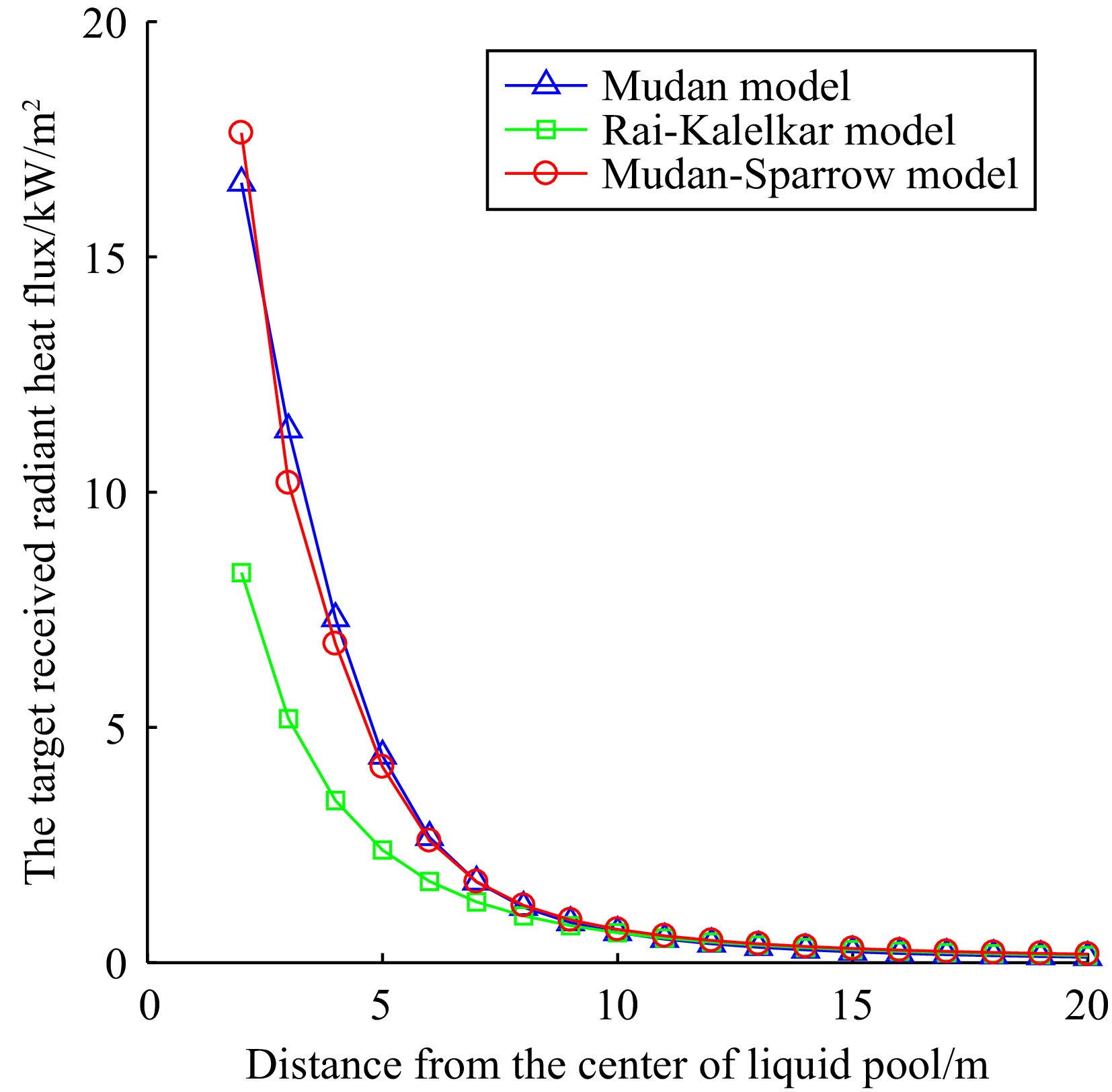
Figure 1.
The target received radiant heat flux with a small hole leak.
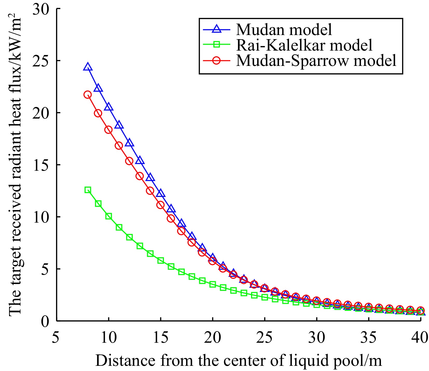
Figure 2.
The target received radiant heat flux with a medium hole leak.
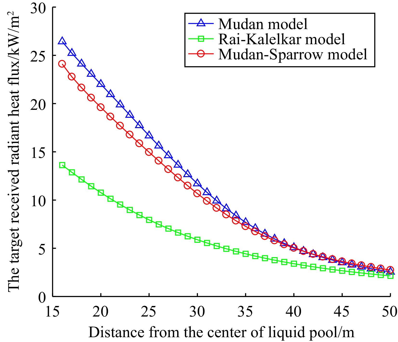
Figure 3.
The target received radiant heat flux with a large hole leak.
According to Table 3, it can be seen that as the distance between the target and the center of the liquid pool increases, the view factor and the target received radiant heat flux gradually decrease, which is consistent with the actual situation.
According to Figs 1−3, it can be seen that there are differences in the calculation of the target received radiant heat flux by the three models. As the distance between the target and the liquid pool center increases, the three models demonstrate that the target received radiant heat flux decreases, and that the rate of decay similarly reduces with distance. At the same time, the Mudan and Mudan-Sparrow models show similar predictive results and have the fastest decay rates among the three models. In contrast, the radiant heat flux predicted by the Rai Kalelkar model has a relatively slow decay rate.
By combining the data analysis from Table 3 and Figs 1−3, the results of Mudan and Mudan-Sparrow models in predicting radiant heat flux are similar, but there are still some differences between them. In particular, these differences are particularly significant near the liquid pool area. However, as the distance increases, the difference between the two models gradually decreases. This phenomenon is due to the intermediate variable a in the Mudan model depending on whether the target is located within the flame shadow. This will lead to changes in the intermediate variables A and B, thereby affecting the final calculation result. When the target is outside the flame shadow, the calculation results of the two models should be the same in theory. Due to the different methods of calculating the intermediate variables, there is a slight difference in the actual results.
The calculation of the Rai-Kalelkar model shows that the radiant heat flux is about half of the heat flux in the first two models. This is because the Rai-Kalelkar model does not consider the impact of the flame tilt angle on the radiant heat flux during the calculation process.
Fire separation distance
-
In assessing the potential risk of pool fires on adjacent storage tanks or equipment, radiant heat intensity is a main element. When the radiant heat intensity exceeds a certain threshold, the adjacent storage tanks may reduce material strength due to overheating. This can result in structural failure, equipment damage, and personnel casualties. The thermal radiation damage/injury criteria are as shown in Table 4.
Table 4. Thermal radiation damage/injury criteria.
Incident flux I (kW/m2) Damage to equipment Injury to personnel 37.5 Total damage to operating equipment 1% dead/10 s; 100% dead/min 25.0 The minimum energy required for wood combustion under
the absence of flame and long-time radiationSignificant injury/10 s; 100% death/1 min 12.5 The minimum energy required for wood combustion and
plastic melting under the presence of flameFirst-degree burns/10 s; 10% death/1 min 4.0 Glass breaks after 30 min of exposure More than 20 s feeling pain, may not be blistering According to the 'Code for Design of Building Fire Protection' (GB 50016-2014, 2018 edition) code 3.4.6: When Class A liquids are stored in outdoor equipment, the distance from adjacent factories should not be less than 12 m; for Class B liquid, the distance should not be less than 10 m[17]. In the scenario selected for this paper, the distance between the outer edge of the fire dike of the storage tank and the adjacent building is approximately 10 m. The distance between the outer edge of the storage tank and the adjacent building is approximately 13 m, which meets the above-mentioned code requirements.
In fire engineering design, the point source model serves as one of the crucial bases for determining the minimum fire separation distance. The point source model helps assess the propagation characteristics of flames and thermal radiation under specific conditions. Based on these assessment outcomes, professionals can calculate the minimum safety distance required under given conditions to prevent flame spread or avoid igniting of adjacent combustible targets due to thermal radiation. This section compares and analyzes the point source model with three other models.
Taking into account that the radius of a liquid pool created by a large hole leak in the storage tank would be 15.2654 m, greater than the distance between the tank and the workshop. When the storage tank is equipped with a fire dike, the effects of a large hole leak are comparable to those of a medium hole leak. Therefore, the analysis is limited to the radiant heat flux during small and medium hole leaks under wind-affected conditions. The relationship between the radiant heat flux and distance for four different models is shown in Fig. 4. By comparing Figs 2 and 4b, it is shown that the fire dike can significantly reduce the radiant heat flux received by the target.
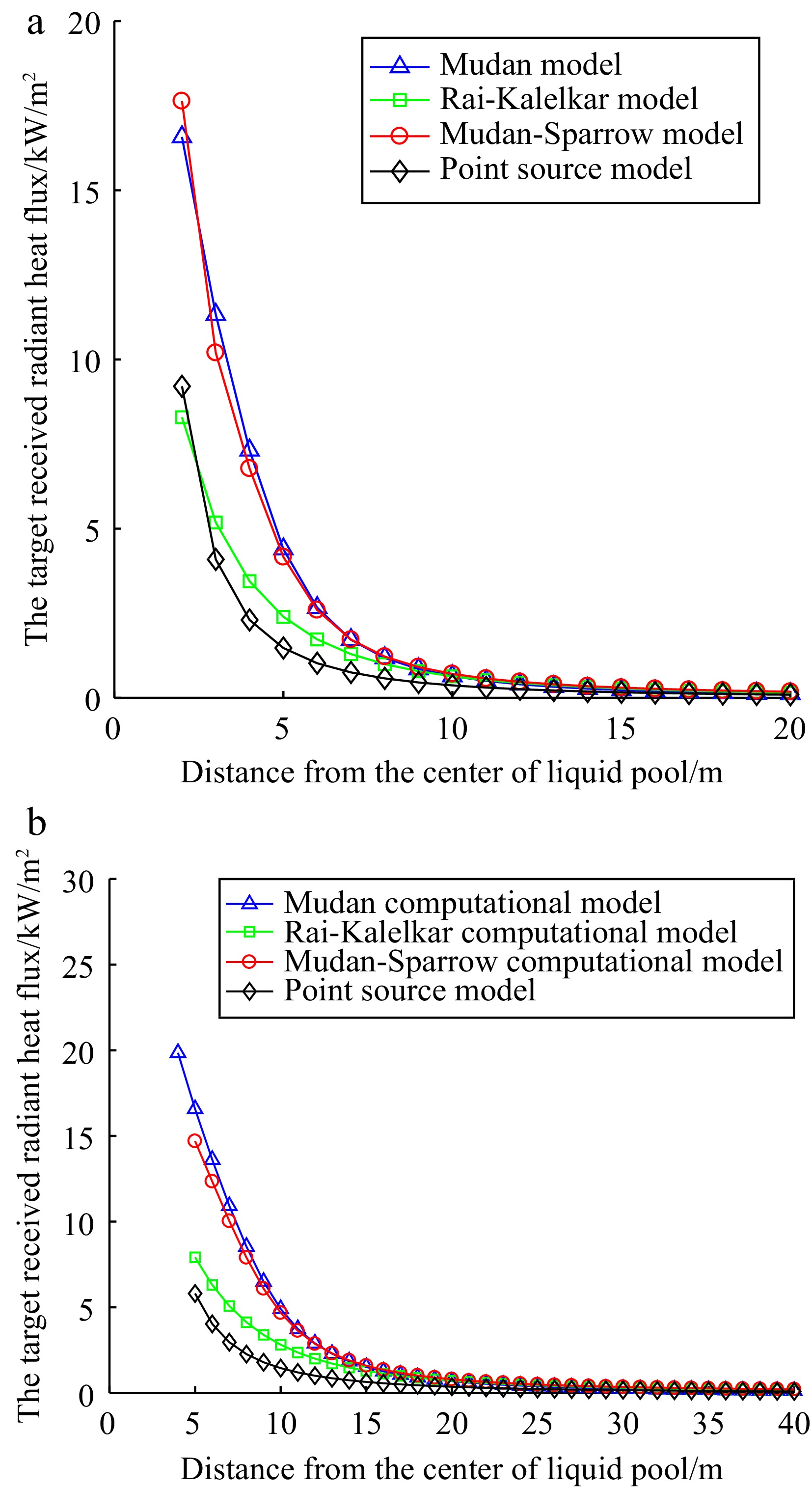
Figure 4.
The target received radiant heat flux: (a) small hole leak, (b) medium hole leak.
As shown in Fig. 4, under the scenario considering medium or larger leak, the calculated results of the Mudan, Mudan-Sparrow, and Rai-Kalelkar models are more conservative than those of the point source model.
This also shows that when determining the minimum fire separation distance around storage tanks with a fire dike, these three models can provide a greater safety margin compared to the point source model, therefore enhancing the protective effect of preventive measures.
Further analysis shows that the actual distance between the center of the storage tank and the exterior wall of the workshop is 13.35 m. For the point source model, using expression (11), it is calculated that in the not equipped with a fire dike, the exterior wall of the workshop received radiant heat flux due to small and medium hole leak is 0.2066 and 3.4570 kW/m2, respectively. However, when the storage tank is equipped with a fire dike, the radiant heat flux due to a medium hole leak decreases to 0.8142 kW/m2.
At the same time, for the other three models, considering wind-affected situations, when the storage tank is equipped with a fire dike and a medium hole leak occurs, the target received radiant heat flux at 13.35 m is shown in Table 5.
Table 5. The target received radiant heat flux at a distance of 13.35 m.
Serial number Model Distance from the center of liquid pool (m) The target received radiant heat flux (q/kW/m2) 1 Point source model 13.35 0.8142 2 Mudan model 2.1215 3 Mudan-Sparrow model 2.1548 4 Rai-Kalelkar model 1.6273 As can be seen from Table 5, at 13.35 m away from the workshop, the radiant heat flux received by the external wall of the workshop calculated by different models is significantly different. The point source model predicts the lowest radiant heat flux. This is attributed to its simplification of the fire source to a point, without comprehensively considering complex factors such as the geometry and scale of the flame. In contrast, the Mudan and Mudan-Sparrow models produced similar results and relatively higher values in the four models. The Rai-Kalelkar model calculated results fall between those of the point source and Mudan models. It provides a compromise predictive method.
According to Table 4, in scenarios affected by wind and equipped with a fire dike, the impact of liquid pool radius on radiant heat flux and potential hazards of pool fires is analyzed using four models. The specific analysis results are presented in Table 6.
Table 6. Thermal radiation hazard consequence.
The target received
radiant heat flux
(q/kW/m2)Damage distance/m Point source model Mudan Rai-Kalelkar Mudan-Sparrow Liquid pool radius = 1.5256 m 37.5 — — — — 25 — — — — 12.5 1.7165 2.7515 1.5672 2.4835 4 3.0343 5.1796 3.618 5.0796 Liquid pool radius = 3.35 m 37.5 — — — — 25 — — — — 12.5 3.4661 6.4002 2.0926 5.9354 4 6.1272 10.7444 8.1554 10.6076 In general, the heat radiation threshold that the exterior wall of a building can withstand, also known as the critical heat flux that does not lead to ignition, is approximately between 12.5 and 25 kW/m2. In order to ensure the safe evacuation of personnel, this threshold should be further reduced to approximately 4 kW/m². According to Table 6, when the leak of the storage tank occurs in the medium hole or above, the safety distance of the radiant heat flux predicted by the point source model is 6.1272 m at 4 kW/m². However, the predicted safe distances by the Mudan, Mudan-Sparrow, and Rai-Kalelkar models at a heat radiation level of 4 kW/m² are greater than those of the point source model.
Furthermore, there are differences among models in assessing the safety of the thermal radiation threshold. The Mudan and Mudan-Sparrow models produce more conservative results, exhibiting that these models tend to provide a larger safety margin when predicting safe distances. Compared to the Rai-Kalelkar model, the point source model offers more conservative predictions within the vicinity of the center of the liquid pool. However, as distance increases, the predictive results of the Rai-Kalelkar model become more conservative. This is because variable q is inversely proportional to variable L in the point source model. Therefore, the rate of decline in the point source model is more rapid. The closer to the center of the liquid pool, the greater the target received radiant heat flux.
It is worth noting that GB 55037-2022 presents new standards for determining fire separation distance. It requires establishing fire separation distance based on the critical ignition heat intensity of building exteriors. Therefore, according to the results of the calculations in Table 6 and the selected models, combined with the actual situation of the factory, the fire separation distance between the storage tank and buildings can reasonably be adjusted. This not only helps to optimize the layout of the plant area but also ensures satisfaction with fire protection design codes.
-
The calculation results of the Mudan, Mudan-Sparrow, and Rai-Kalelkar models show that the target received radiant heat flux decreases with increasing distance, and as the distance further increases, the rate of attenuation gradually slows down. The calculation results of the Mudan and Mudan-Sparrow models are similar. The attenuation trend is faster than that of the Rai-Kalelkar model.
Comparing the Mudan and Mudan-Sparrow models, we see a significant difference in the calculated radiant heat flux when the target is close to the liquid pool. This difference decreases as the distance between the target and the center of the liquid pool increases. Therefore, when selecting a model for predicting radiant heat flux, the relative position of the target and the fire source must be considered, as well as differences in parameter settings within the models. In practical applications, to ensure the accuracy and reliability of evaluation results, models should be selected based on specific scenarios and required accuracy.
The Mudan, Mudan-Sparrow, and Rai-Kalelkar models produce more conservative results and a larger safety margin compared to the point source model when considering the equipment with a fire dike. Furthermore, there are significant differences in the calculation results of the radiant heat flux received by the exterior wall of the building at a relatively long distance. The Mudan and Mudan-Sparrow models provide similar and the highest results, followed by the Rai-Kalelkar model, while the point source model produces the smallest results. Therefore, choosing the appropriate model is critical to ensuring adequate fire separation distances in storage tank fire scenarios. The choice of model should be based on a comprehensive consideration of the flame characteristics and a concrete understanding of the fire scenario to ensure adequate safety provision.
There are differences among models in assessing the safety of thermal radiation threshold values. The results of the Mudan and Mudan-Sparrow models are more conservative. The calculated results of the point source model and the Rai-Kalelkar model show differing trends with increasing distance from the center of the liquid pool. At closer distances to the center of the liquid pool, the point source model provides more conservative results. At greater distances to the center of the liquid pool, the Rai-Kalelkar model provides more conservative results. Therefore, in practical applications, the choice of model should be determined by the specific requirements for safety threshold protection levels in a specific scenario. This is to ensure the accuracy and applicability of the assessment results.
Through the research and analysis of the four models, we can accurately grasp the combustion characteristics of pool fires and the propagation mode of thermal radiation. Analyzing the fire separation distances between the actual storage tank and the workshops provides theoretical support for the evaluation of the quantitative fire separation distances. It provides references for plant layout, safety and fire protection design, fire risk assessment, and emergency response in the petroleum and chemical industries.
-
The authors confirm contribution to the paper as follows: data collection, processing and paper writing: Wang W; reviewed the results and approved the final version of the manuscript: Tao G, Zhang L. All authors reviewed the results and approved the final version of the manuscript.
-
The data used to support this study are included within this published article.
-
Thanks to the two teachers for their advice and help in the process of writing this paper, thanks to each person who provided help in publishing this paper.
-
The authors declare that they have no conflict of interest.
- Copyright: © 2024 by the author(s). Published by Maximum Academic Press on behalf of Nanjing Tech University. This article is an open access article distributed under Creative Commons Attribution License (CC BY 4.0), visit https://creativecommons.org/licenses/by/4.0/.
-
About this article
Cite this article
Wang W, Tao G, Zhang L. 2024. Comparative and analysis study of pool fire radiant heat models under different view factor calculations. Emergency Management Science and Technology 4: e003 doi: 10.48130/emst-0024-0005 

Comparative and analysis study of pool fire radiant heat models under different view factor calculations
- Received: 20 December 2023
- Accepted: 05 March 2024
- Published online: 25 March 2024
Abstract: According to the provisions on fire separation distance between industrial and civil buildings in the latest 'General Code for Fire Protection of Buildings and Constructions' (GB 55037-2022). Radiant heat intensity is one of the main factors in calculating the fire separation distance between buildings. Therefore, the design process involves a lot of calculation of radiant heat intensity. This paper mainly studies the prediction model of radiant heat flux. Three different view factor calculation models, Mudan, Mudan-Sparrow, and Rai-Kalelkar, are used to evaluate the influence of key factors such as the diameter of the pool and the distance between the target and the center point of the liquid pool on the calculation results of radiant heat flux. The results show that when it came to estimating the radiant heat flux, the Mudan and Mudan-Sparrow models yielded comparable results. The calculation of the Rai-Kalelkar model shows that the radiant heat flux is about half of the heat flux in the first two models. When calculating the minimum fire separation distance for combustible liquid storage tanks with a fire dike, the results show that all three models can provide a larger safety margin than the point source model.
-
Key words:
- Pool fire /
- Thermal radiation /
- View factor /
- Calculation model /
- Fire separation distance