


-
The fire safety hazards in an orbiting spacecraft such as the International Space Station are not entirely resolved due to limited escape options. Flame spread behavior when gravitational forces become miniscule, has gained increasing attention. The magnitude of a forced flow in an order of 0.1–0.3 m/s, which is typical of air circulation speeds in a spacecraft, is much smaller than the buoyancy-induced flow of several m/s in normal gravity. A flame front at Earth gravity is essentially a buoyancy-controlled plume, for which oxygen is drawn into the chemical reaction zone for sustaining efficient combustion. As a result, substantial unburnt gases including soot and luminous radiation are unimportant for the flame size smaller than about 40 cm[1]. In the absence of gravity, a co-current boundary layer diffusion flame is established via diffusion of heat and mass even by low forced oxidizer flow over the fuel surface[2] with a radiant fraction up to 0.6[3] compared to 0.09 at Earth gravity. Peak soot-volume fractions at microgravity increase by a factor of two times as compared to that at Earth gravity for laminar acetylene jet diffusion flame[4]. Through the elimination of buoyancy, flammability and flame spread over electric wire or solid fuel beds are illustrated[5, 6]. The consensus provided by several works[1, 6−8] is that flame spread is highly configuration dependent as a function of confinement size, and characteristic times on gas-phase flow, diffusion, chemical reaction and conduction. The behavior of flame spreading over thin solids is numerically investigated by using radiation models with constant absorption coefficient[9, 10]. An increase of a dimensionless volume coefficient conducts to a significant soot-related radiative feedback[11−13] due to an ever-thickening diffusion flame. An inverse dependence of soot formation on the mainstream flow speed is shown from gas fuel microgravity flames with a fixed burning rate[12]. Extinction of upward spreading flames over a thin solid fuel is strongly linked to a critical oxygen concentration[14] with opposed-flow at microgravity. The competing effects of diffusion, fuel injection and oxidizer flow velocity at microgravity play a key role on flame quenching due to soot-related radiative loss[15]. A reacting boundary layer with blowing is described by a self-similar solution[16, 17], which can’t be directly applied to a microgravity flame spread at very-low-flow speeds due to absence of thermal radiation.
Meaningful studies in microgravity are reported on soot-related flame spread with a selected gas[2, 11−13] or solid combustible materials[1, 6−8, 18, 19]. Unfortunately, the context of the toxic species composition has not been given specific attention because the measurement of soot, CO and unburnt hydrocarbons creates an insurmountable difficulty during airplanes flying parabolic trajectories[12, 13, 15]. Besides, because of flame-induced buoyancy, the environmental conditions of a spacecraft can’t be reproduced at a slow velocity flow on Earth. The decision making process regarding the main threat of the toxic species on the spacecraft crews survivability depends increasingly on numerical simulations. Innovation of this work is to investigate numerically the consequences of oxidizer flow speed on the major toxic species from liquid fuel flame under weightless conditions. Liquids (mineral oil, synthetics, etc.) could originate from various machineries to be used in spacecraft. Liquid fuels such as heptane and dodecane are chosen, because their detailed thermo-physical and combustion properties are available, although these fuels may never be used in spacecraft. On the other hand, this allows the identification of the impact of a significant difference in boiling temperatures on flame burning rate and associated toxic emission. Soot is modeled by using an acetylene/benzenz based two-equation model[20] for the calculations of microgravity flame spread over an insulated electrical wire[19] or a flat plate[21]. For this, a detailed ethylene kinetic reaction mechanism is required, and the semi-empirical parameters related to soot formation processes[20] should be initially calibrated. The novelty of this study is implemention of a LSP (Laminar Smoke Point) model[22] in FDS6.7[23], allowing the provision of a general and practical solution for soot modeling in multi-fueled fires without knowing the exact elementary reactions. A simple soot conversion model used in FDS6[23] can’t be directly applied to a heavily sooting, microgravity boundary layer flame. The species concentrations CO of Earth gravity free-burning fires are essentially independent of the HRR (Heat Release Rate) with a peak of about 5%[24]. This study indicates that the chemical composition of microgravity flames depends on the type of the liquid fuel, and a higher HRR has much greater tendencies to emit large CO and soot species. Furthermore, an important finding of this study is that, in contrast to the case with porous gas burners[12], an increase of oxidizer flow speed is favorable for toxic species production from microgravity flames because of an enhancement in burning rate.
-
The numerical model includes the solution of the overall continuity equation, the Navier-Stokes equations in the transient three-dimensional formulation, and transport equations for gas-phase species mass fractions and energy. A detailed description of the physics-based equations and the Direct Numerical Simulation method can be found in the FDS6.7 user guide[23].
In this study, reactions from Westbrook & Dryer[25] are assumed to account for carbon monoxide production via the two sequential, semi-global steps:
$\rm C_m H_n \, + \,\left( {\dfrac{m}{2} + \dfrac{n}{4}} \right)\, O_2 \, \to m\,CO\, + \,\dfrac{n}{2}\, H_2 O $ (1) $\rm CO\, + \,\dfrac{1}{2}\,\, O_2 \, \Leftrightarrow {CO}_2 $ (2) The primitive fuel oxidation (1) is a fast chemical reaction which is combined with finite-rate reversible carbon monoxide reaction (2) by using the modified Arrhenius parameters from Andersen et al.[26].
Soot formation accounts for both soot nucleation, surface growth and oxidation by oxygen. The soot nucleation process is expressed in terms of Laminar Smoke-Point (LSP) concept[22] as follows:
$ \rm \dot \omega _{s,\,N}^{'''} = {A_f}{\rho ^2}{T^{2.25}}\dfrac{{f - {f_{st}}}}{{1 - {f_{st}}}}\exp ( - 2000/T) $ (3) Here,
$ \rho $ Table 1. Summary of LSP height and pre-exponential factor, Af, for three types of fuel.
Fuel type LSP (m) Af Ethylene (C2H4) 0.106 4.1 × 10⁻⁵ Heptane (C7H16) 0.147 2.9 × 10⁻⁵ Dodecane (C12H26) 0.137 3.1 × 10⁻⁵ $\rm \dfrac{{{A_{f,Fuel}}}}{{{A_{f,{C_2}{H_4}}}}} = \dfrac{{{L_{{C_2}{H_4}}}}}{{{L_{Fuel}}}} $ (4) The surface growth rate[28] is usually evaluated using local temperature, T, soot number density, N, and mole fraction of the parent hydrocarbon, XF.
$ \dot{{\omega}^{'''}_{{s},\; G}}={ }_{{C}_{\gamma}} \rho {T}^{1 / 2} {X}_{{F}} \exp \left(-{T}_{\gamma} / {T}\right) {N}^{1 / 3}\left(\rho {Y}_{{s}}\right)^{2 / 3} $ (5) The empirical parameters,
$\rm C_\gamma \; and\; {T}_\gamma $ $\rm C_{soot}+O_{2} \to CO_{2} $ (6) The
$ {\mathrm{O}}_{2} $ $\rm \dot{\omega}^{'''}_{s,\,O}=-4.7 \times 10^{10}[Ys][Yo] \exp (-211000 / R T) $ (7) Here, R denotes the gas universal constant. A detailed description of the physics-based equations for soot formation is presented in a previous publication[30].
The evaporation rate of liquid as heptane or dodecane is governed by Stefan diffusion as a function of mass fraction of fuel vapor at the interface:
$\rm \dot{m}_{F}^{''}=\dfrac{\rho \mathrm{D}}{\mathrm{L}} \mathrm{Nu} \ln \left[\dfrac{1-\mathrm{Y}_{\mathrm{F}, \infty}}{1-\mathrm{Y}_{\mathrm{F}, \mathrm{i}}}\right] $ (8) Here,
$ \rho $ $\rm Y_{F,i} = \dfrac{{W_F }}{{ W_m }}\exp \left[ { - \dfrac{{L_vW_F }}{R}\left( {\dfrac{1}{{ T_s }} - \dfrac{1}{{ T_b }}} \right)} \right] $ (9) Here, WF /Wm denotes molar weight of liquid fuel/mixture, R gas universal constant and Lv pyrolysis heat. Table 2 lists the thermo-physical and combustion properties of heptane and dodecane[31]. The liquid fuel itself is treated to be thermally-thick, a one-dimensional heat conduction equation for liquid temperature is applied. The convective heat flux,
$ \rm{\dot{q}}_{conv}^{''} $ $ \rm{{ \dot{q}}}_{rad}^{''} $ Table 2. Thermo-physical and combustion properties of heptane and dodecane.
Property Heptane Dodecane Conductivity k (W/m·K) 0.17 0.14 Density ρ (kg/m3) 684 750 Heat capacity Cp (kJ/kg·K) 2.24 2.21 Pyrolysis heat, Lv (kJ/kg) 321 256 Heat of combustion, ΔHc (kJ/kg) 44500 44147 Boiling temperature Tb (°C) 98 216 -
Measurement of soot emission by using a small square gas burner with dimensions of Lp = Wp = 5 cm was conducted during airplanes flying parabolic trajectories[12, 13] due to the limited space and amount of feed gases available. The soot volume fraction of ethylene laminar diffusion flame in microgravity is measured by using the laser induced incandescence technique (LII)[12, 13]. The LII intensity image is converted to soot volume fraction distribution, and the measurement accuracy depends on a proportionality constant which is required for correction due to attenuations of both the laser beam and the collected signal. However, in the current numerical works, we lack the ability to quantitatively specify the measurement errors. To avoid the coupling between heat feedback and fuel supply, ethylene with a burning rate of 5 g/m2s was injected through a porous burner, and measurement of soot formation can be achieved in a short microgravity test duration of roughly 22 s. In a spacecraft, air circulation speed is an order of 0.1–0.3 m/s with an enriched ambient oxygen. Thus, the oxidizer flow with an oxygen concentration of 0.35 and a velocity of U0 = 0.2 m/s are chosen for the experimental investigation[12, 13]. To avoid a large computational domain, high-fidelity geometric simulations can be configured in Fig. 1a & b by using such reduced experimental plate dimensions and gas burner[12, 13]. Three-dimensional simulations are considered with an overall computational domain of 8Lp in the windward direction (×), and 4Lp in both the lateral (y) and normal (z) directions. The computational domain is divided into 200 (x) × 100 (y) × 75 (z) cells by using a uniform mesh size of 2 mm[11, 21]. The multiple meshes are used with 20 processors through parallel processing of a Linux cluster. With a mesh size of 2 mm, a typical simulation during a physical time of 10 s requires roughly 150 CPU hours. A proper cell sensitivity analysis on the predicted quantities was taken in the previous work[21], and a deviation of roughly 5% is identified by reducing the grid size from 2 to 1 mm for the peak of flame temperature. However, a reduction in the grid size to 1 mm results in a significant reduction in the time step (
$ \Delta t $ 
Figure 1.
Computational details and the coordinate system. (a) Flame structure in side view. (b) Disposition of the pyrolysis zone in top view.
Figure 2 shows the computed and the measured soot volume fractions across the height, z, at various axial locations x/Lp = 0.4, 0.8, 1.2, 1.6, 2, and 2.4. The soot volume fraction increases with x/Lp and reaches a peak equal to 10 ppm and is then oxidized as the reaction zone falls down to the pyrolysis zone. The computed soot profiles are consistent with the measurement in terms of location, shape, and peak value. Nevertheless, at x/Lp = 1.2 just downstream the pyrolysis zone, the computed peak occurs at a higher value of z as compared to the experiments, implying an over-prediction of soot layer thickness. Moreover, an over-prediction of about 20% by the soot model at x/Lp > 2 far away from the tailing edge is observed, which suggests that the model underestimates local soot oxidation associated with air entrainment and product dilution or overestimates soot nucleation. Indeed, the numerical model predicts a thicker soot emission layer than that of the measurement. This is partially attributed to soot oxidation via the radicals OH which can’t be included in the two sequential, semi-global chemical reactions (cf. Eqns 1, 2). Globally, the comparison is deemed satisfactory with an uncertainty within 20%, considering all the simplifying assumptions made in the global soot model and uncertainties in measuring local soot concentration in microgravity conditions during parabolic flights[12, 13]. In spite of the difference between the numerical and the experimental results, any attempt to calibrate the empirical parameter in soot model for matching the experimental data is discouraged due to lack of the model generalizability. As per the recent results of such studies available in the work [19], verification of the results with experimental data for microgravity flame shows also some uncertainty in soot model. A relatively good estimation of soot emission allows to calculate properly the contribution of the radiation heat flux over the liquid surface in vitiated air boundary layer.
Figure 2.
Computed and experimental profiles of soot volume fraction for ethylene flame at different locations x along the height z.
Figures 3, 4a & b illustrate the predicted liquid temperature and mass loss rate (MLR) for evaporated heptane and dodecane along x on the central line (y = 0, cf. Fig. 1) at the different physical times for U0 = 0.2 m/s. The heat feedback from the post-combustion gases allows preheating of the virgin liquid fuel, and to increase progressively the liquid temperature with time. From Table 2, it can be seen that the boiling temperature of heptane (98 °C) is smaller by a factor of 2.1 times than that of dodecane (216 °C). Based on Eqns 8 and 9, sufficient volatiles to sustain gas ignition of the pyrolyzate and oxidizer mixture are generated when the temperature of heptane reaches about 60 °C, and that of dodecane reaches 160 °C. The pyrolysis rate (cf. Fig. 4) curve shows a growing trend with liquid temperature (cf. Fig. 3), and asymptotically reaches a higher peak of about 25 g/m2s for heptane and 20 g/m2s for dodecane near the leading edge when the liquid temperature approaches a steady state. The time to reach a steady mode is about 10 s, implying the most devastating fire scenario because the pyrolysis rate is close to a maximum, as presented in Fig. 5a & b for oxidizer flow velocity in a range of 0.1 to 0.3 m/s. The peak of pyrolysis rate increases by a factor of roughly two times by increasing oxidizer flow velocity from 0.1 to 0.3 m/s because of reduction in flame stand-off distance which tends to an enhancement of heat feedback. At U0 = 0.3 m/s, MLR exhibits a peak of 32 g/m2s for heptane and 22 g/m2s for dodecane near the leading edge with an increase by a factor of 50%. A sharp decrease of MLR beyond the leading edge is attributed to an insufficient heat feedback from the flame with an increase in the flame stand-off distance (cf. Fig. 1a). A propagation of the pyrolysis front of dodecane can be sustained solely for the liquid temperature above 130 °C, and its pyrolysis front length increases from x/Lp = 0.4, 0.6 to 0.8 (cf. Fig. 5b) due to enhanced feedback with a reduction in flame stand-off distance by increasing oxidizer flow speed from 0.1 to 0.3 m/s. In fact, the significant difference in the pyrolysis rate distribution between dodecane and heptane is mainly attributed to the liquid boiling temperature, which affects sensitively the flame behaviour, radiation, combustion heat and other parameters via MLR.
Figure 3.
Profiles of the surface temperature of (a)heptane and (b) dodecane as a function of time at U0 = 0.2 m/s.
Figure 4.
Spatial distribution of the computed pyrolysis rate over (a) heptane and (b) dodecane surfaces for the different times at U0 = 0.2 m/s.
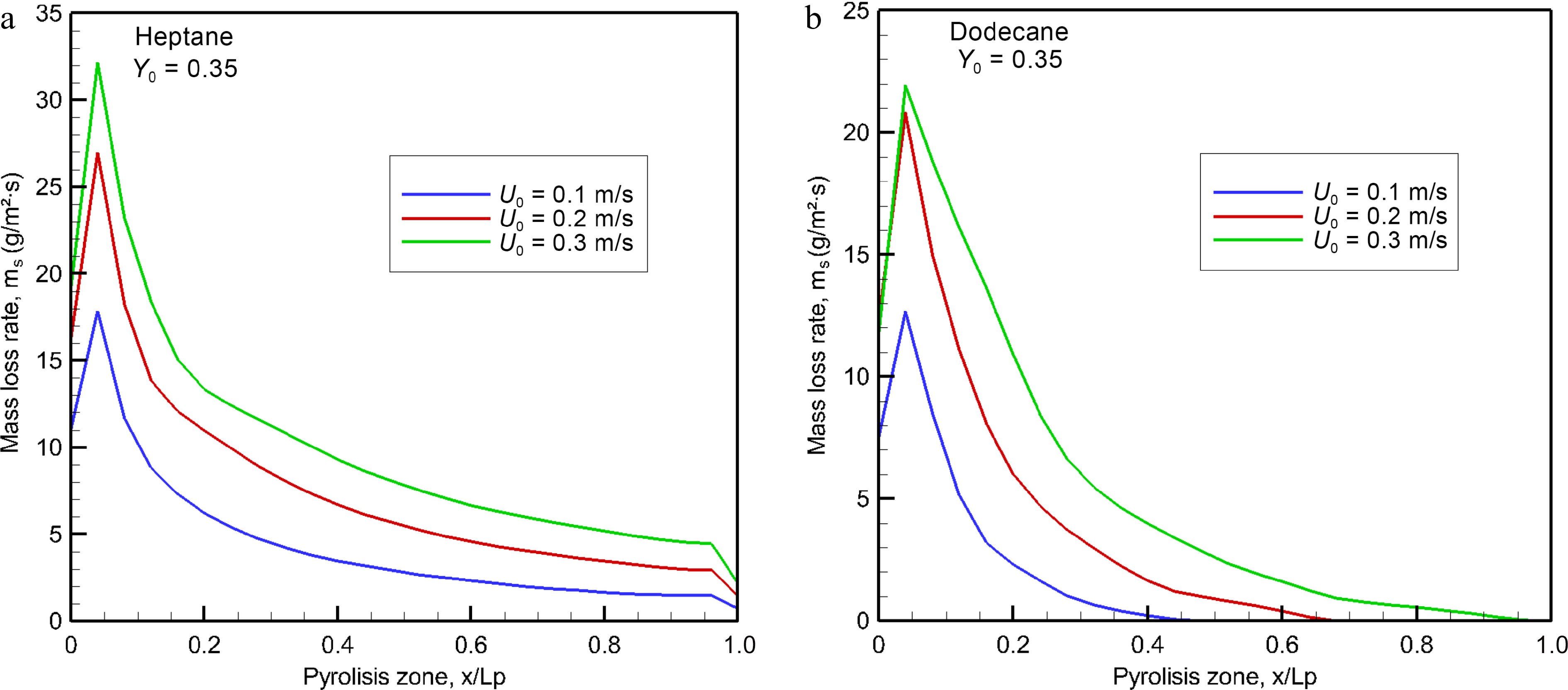
Figure 5.
Computed burning rates of (a) heptane and (b) dodecane at the steady mode as a function of oxidizer flow velocity.
Due to the absence of natural convection in microgravity, a co-current boundary layer diffusion flame is expected to be laminar regardless of the geometrical scale[1]. Thus, generalizability of the simulation results from a reduced scale experimental device can be preserved by normalizing the physical quantity via its geometrical length of Lp = 5 cm or its area (LpxLp). The heat release rate (HRR, kW) at the steady mode is normalized by the pyrolysis area (Per Unit Area, m2), and response of HRRPUA, qpyro (kW/m2), to the change in oxidizer flow velocity, U0, is examined in Fig. 6a. It is worthwhile to note that the HRRPUA is determined from division of the theoretical HRR, QT
$ \mathop { = \dot m}\nolimits_s^{} \,\,\mathop H\nolimits_c $ 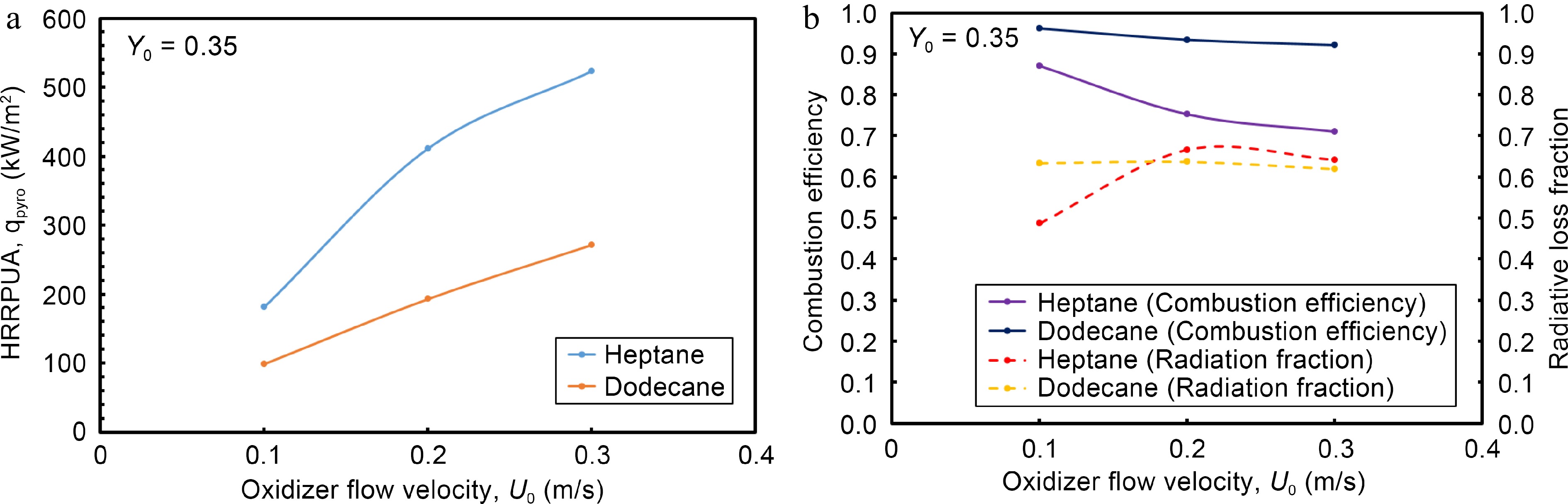
Figure 6.
Impact of oxidizer flow velocity on (a) HRRPUA, (b)combustion efficiency and radiation fraction at the steady mode.
The radiative loss fraction, QR/Q, is plotted versus oxidizer flow velocity in Fig. 6b. By solving the radiation transfer equation, integration of the local radiation heat flux over all cells with an overall computational boundary allows to monitor the global radiation heat loss rate, QR[23]. The heat release rate, Q, is calculated from the combustion model based on an Eddy Dissipation Concept[23] via the two sequential, semi-global chemical steps (Eqns 1, 2). The plot of QR/Q indicates that this ratio is higher than 0.5, and increases up to 0.68 at oxidizer flow velocity of 0.3 m/s. This implies that in the absence of natural convection, radiation loss becomes the primary variable triggering diffusion flame quenching. Evolution of combustion efficiency versus oxidizer flow velocity is also presented in Fig. 6b. It is determined from the ratio, Q/QT, where QT denotes the theoretical HRR and Q the effective HRR from Eqn 8. It is found that combustion efficiency of the heptane flame decreases monotonically from 0.9 to 0.7 with an increase in oxidizer flow velocity from 0.1 to 0.3 m/s due to augmentation of MLR (cf. Fig. 5a). Combustion efficiency of the dodecane flame is less sensible to the variation of oxidizer flow velocity with a value in a range of 0.9 to 0.95 as a consequence of its limited pyrolysis zone of x/Lp = 0.4−0.8 (cf. Fig. 5b). With a fixed burning rate[12], an increase in oxidizer flow speed improves combustion efficiency of gas fuel microgravity flames because of an inverse dependence of unburnt gases on the mainstream flow speed. Since evaporation temperature is usually smaller for liquid than all solid fuels[6−8], variation of pyrolysis rate of solid fuel is usually less sensitive to a slight increase in oxidizer flow speed. However, a sensitive augmentation of pyrolysis rate of liquid fuel (cf. Fig. 5) due to enhanced feedback, with a reduction in flame stand-off distance by increasing oxidizer flow speed from 0.1 to 0.3 m/s results in an excessive fuel supply to the boundary layer. Absence of the lateral entrainment by natural convection in microgravity penalizes the air supply to a boundary layer diffusion flame for sustaining intensive combustion even with an increase in oxidizer flow velocity. An accumulation of unburnt species due to lack of oxygen in the boundary layer lowers the combustion efficiency of liquid fuel microgravity flames.
As shown in Fig. 7a & b, the convection heat flux along the wall surface is normalized by the HRRPUA, qpyro (cf. Fig. 6a) for various oxidizer flow speed. The leading edge is exposed directly to a high flame temperature, promoting a peak in convective fraction of the HRRPUA (cf. Fig. 6a) of about 7% for heptane and 10% for dodecane, i.e. in convective heat flux of roughly 37 kW/m2. The convective fraction of the HRRPUA decreases sharply to reach about 1% above x/Lp = 2 from which the flame is significantly lifted (cf. Fig. 1a) above the wall surface leading to a significant reduction in temperature gradient. Multiple peaks look like numerical artefacts due to restart simulation.
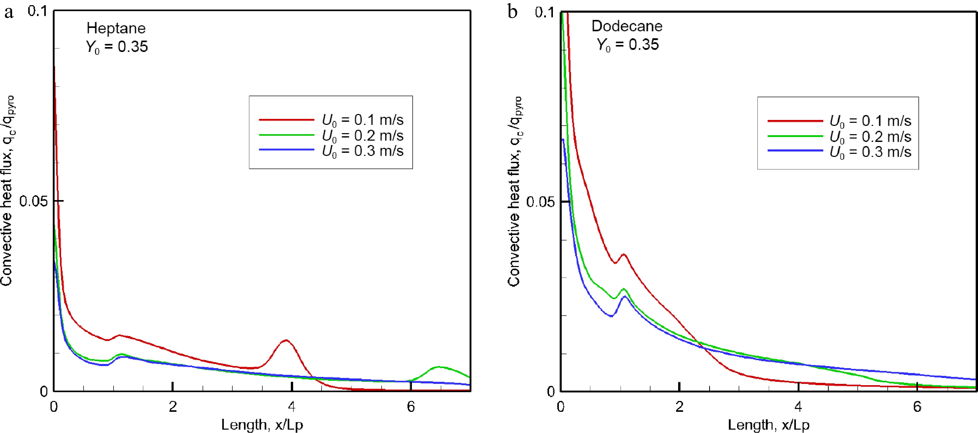
Figure 7.
Evolution of the convective fraction of HRRPUA over pyrolysis surface for different oxidizer flow velocity.
As shown in Fig. 8a & b, the net radiative heat flux along the wall surface is normalized by the HRRPUA, qpyro (cf. Fig. 6a), for various oxidizer flow velocity. The pyrolysis area (x/Lp ≤ 1) is exposed directly to the typically luminous flame, and as a consequence, a part of this region is exposed to relatively high radiative flux that reaches a peak just downstream from the leading edge. Once away from the pyrolysis zone, a sharp decrease in radiative heat flux is found mainly due to reduction in both flame thickness and temperature level. Typically, radiation fraction of the HRRPUA from the heptane flame is degrading due to its decreasing combustion efficiency (cf. Fig. 6b) regardless of oxidizer flow velocity. At U0 = 0.3 m/s, the peak in radiative fraction of the HRRPUA is about 5% for heptane flame, and dodecane flame clearly enhances the radiative fraction with a peak of 8%. It is worthwhile to note that there is a greater radiant heat feedback by a factor of 35% for the heptane flame than for the dodecane flame, although its radiative fraction of the HRRPUA is smaller. At U0 = 0.3 m/s, e.g., the peak in radiant heat flux is about 27 kW/m2 for the heptane flame instead of 20 kW/m2 for the dodecane flame because the enhanced heptane burning rate (cf. Fig. 5a) gives substantial flame length and combustion products. The soot-related radiation flux is about 80% of the total heat flux once away from the leading edge. Typically, a low combustion efficiency (cf. Fig. 6b) translates to a reduction in the heat fraction of HRRPUA, and inversely, a high combustion efficiency conducts to an increase in the heat fraction. A major portion with about 85% of the heat released from combustion is transported by a forward forced convection, and roughly 15% of the combustion heat contributes to the pyrolysis of liquid fuel due to a significant flame stand-off distance.
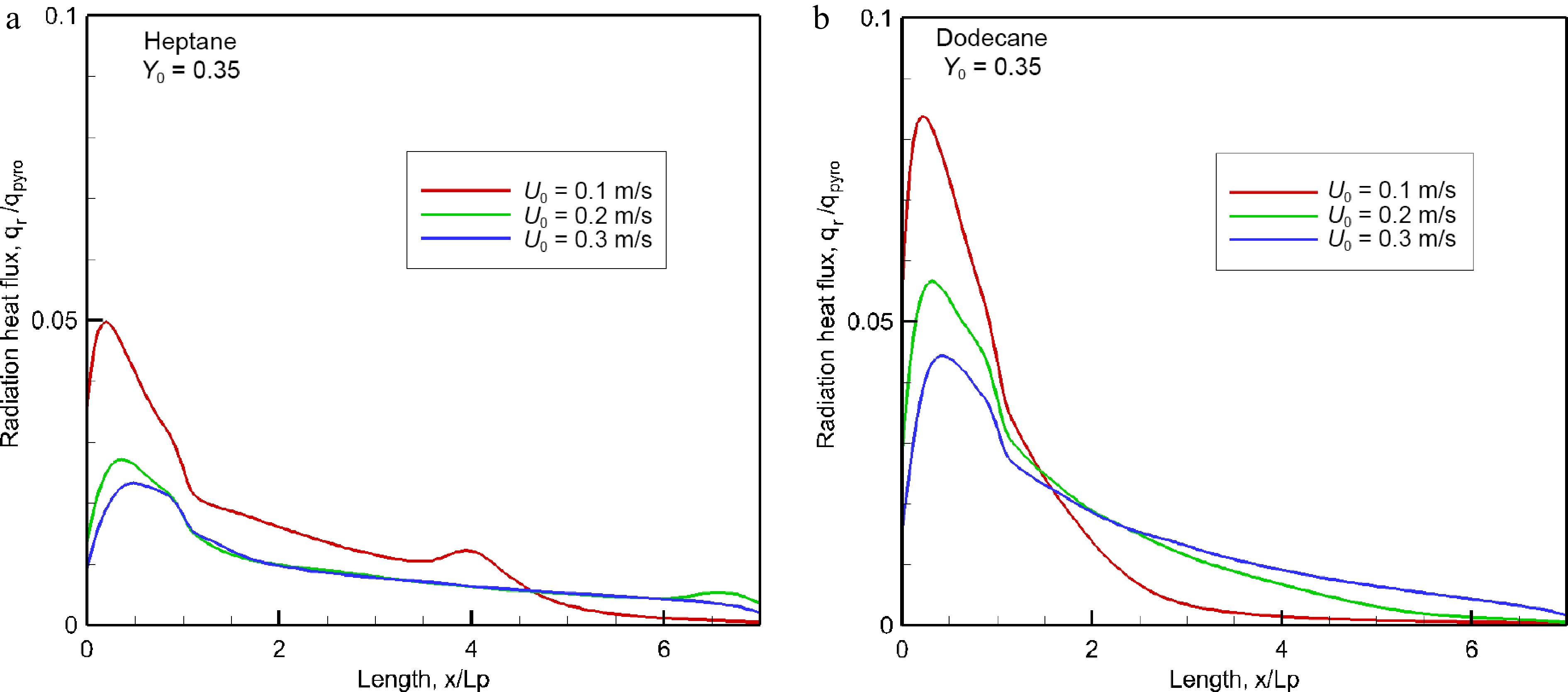
Figure 8.
Impact of oxidizer flow velocity on radiant heat flux over material surface at the steady mode.
Figure 9 illustrates the computed fields of temperature above 600 °C at oxidizer flow velocity of 0.2 m/s for heptane and dodecane. The calculated flame structure is typical of a reactive laminar boundary layer with the diffusion flame being attached to the leading edge where the flame temperature reaches a peak of 1,400 °C. The angle between the dividing line and the xy plane (cf. Fig. 1a) between the oxidizer rich zone and the fuel rich zone is roughly 30°. The flame zone largely extends downstream the trailing edge of the pyrolysis zone (Lp = 0.05 m) due to an excess of pyrolysate. The fuel-oxygen reaction rate highly depend on the oxidizer flow speed, characterized by a lengthening of the flame and in parallel, a significant stand-off distance. The computed flame length, defined as the furthest forward (x) location of the isotherm 600 °C, is 0.35 m for heptane and 0.2 m for dodecane. The temperature level of 600 °C is selected since it is expected to correspond to a threshold above which a majority of the soot-related radiation is responsible to spontaneous ignition of any exposed inflammable object. A strong regression rate of heptane (cf. Fig. 5a) contributes to an increase by a factor of 75% in flame length in comparison with dodecane flame due to its reduced pyrolysis length of x/Lp = 0.4−0.8 (cf. Fig. 5b) as a function of oxidizer flow speed.
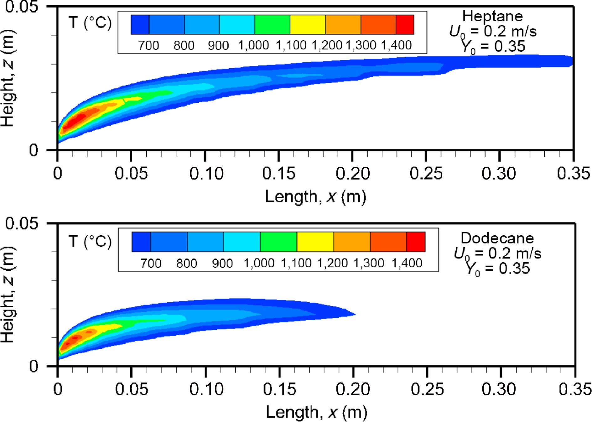
Figure 9.
Computed fields of gas temperature above 600 °C for heptane and dodecane at the steady mode (t = 10 s) at U0 = 0.2 m/s.
Figure 10 depicts the computed fields of soot volume fraction above 7 ppm at U0 = 0.2 m/s for heptane and dodecane flames on the axis of symmetry. In addition, the computed streamlines are plotted on the soot diagram. Soot is located mainly below the diffusion flame sheet (cf. Fig. 9, forming radiation blockage effects in such boundary layer flame (cf. Fig. 8). This deviation of soot particles from the flame is attributed to the strong temperature gradient inside the boundary layer via the thermophoretic effects. The streamlines close to the condensed phase surface are slightly deflected upwards by the flame and fuel injection above the reaction zone. For the heptane flame, the soot volume fraction increases between x = 0.05 m and 0.13 m in the fuel rich part of the flame, and reaches a peak equal to about 30 ppm. However, for the dodecane flame, more soot is located close to the leading edge region because soot is oxidized as the reaction zone falls down to the reduced pyrolysis zone (x/Lp = 0.6 at U0 = 0.2 m). Although dodecane has a higher sooting propensity than heptane (cf. Table 1), the size of the region of higher soot volume fraction above 7 ppm of the heptane flame is roughly four times that of the dodecane flame. This is mainly attributed to a larger fuel rich part of the heptane flame compared to the dodecane flame with a limited pyrolysis zone (cf. Fig. 5a).
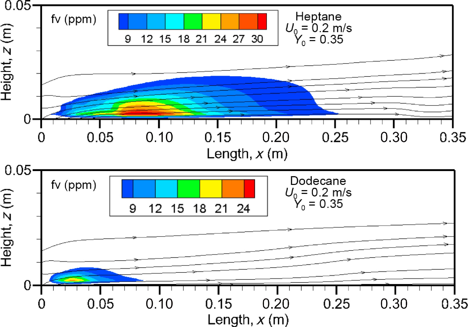
Figure 10.
Computed fields of soot volume fraction above 7 ppm on the axis of symmetry at U0 = 0.2 m/s.
Figure 11a & b shows the computed gas temperature and soot volume fraction above 2 ppm for the heptane flame on the cross-stream plane at the axial location of x/Lp = 2. The size of the region of higher temperature in the cross-section significantly extends the pyrolysis zone [−0.025 m, 0.025 m] far away from the trailing edge due to diffusion of heat and mass. As expected, soot is located in the fuel rich part of the flame, and extent of the soot volume fraction in cross-stream plane is limited to the pyrolysis zone. The soot volume fraction appears to approximately proportional to the oxygen depletion, which implies that soot oxidation processes beyond the flame sheet have ceased and the soot volume fraction is controlled by diffusion.
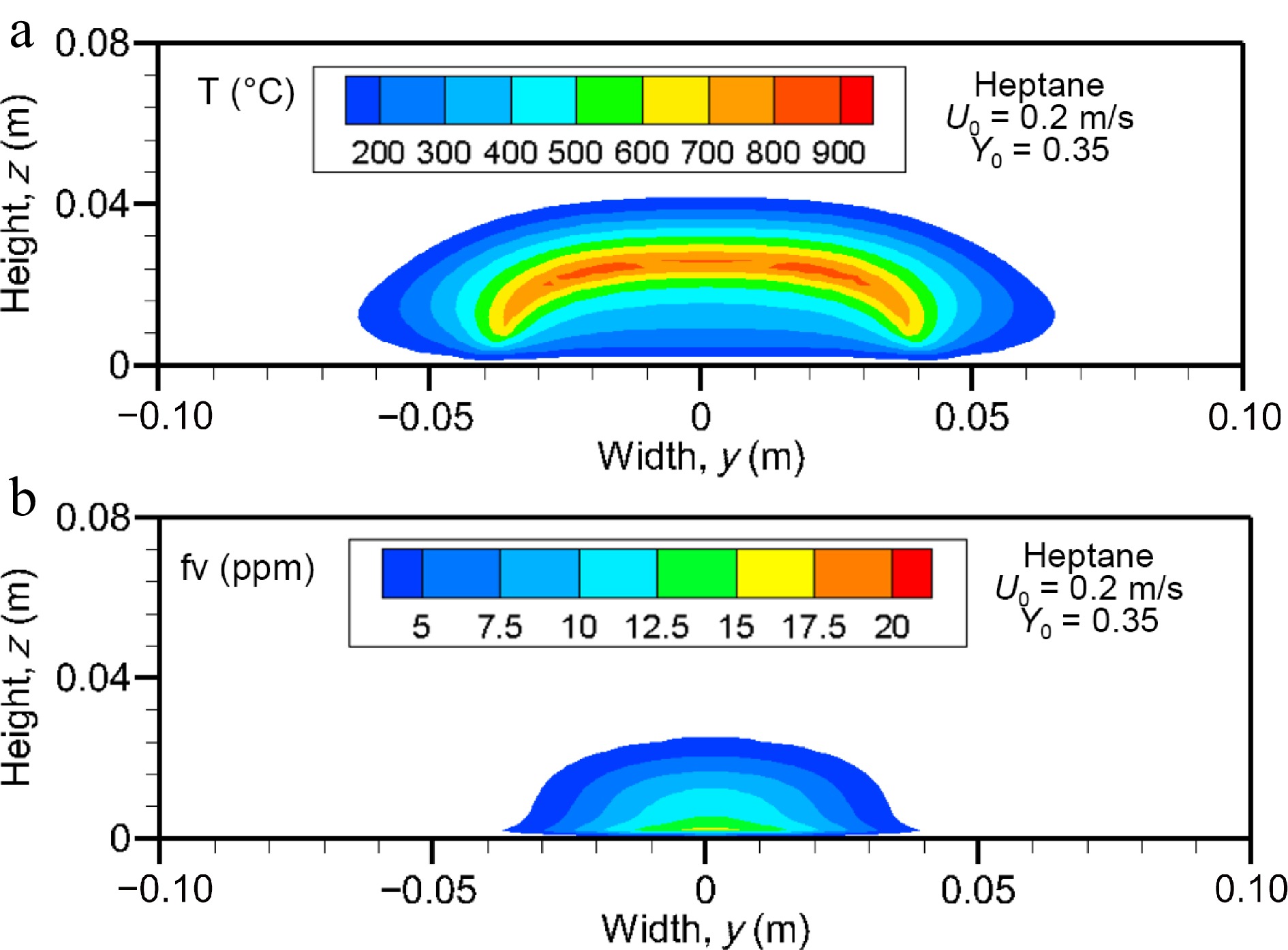
Figure 11.
Computed fields of (a) gas temperature and (b) soot volume fraction (above 2 ppm) on the cross-stream plane for heptane flame at x/Lp = 2 for U0 = 0.2 m/s.
Figure 12a & b show the influence of oxidizer flow velocity, U0, in a range of 0.1 to 0.3 m/s on the mean level of soot volume fraction for the heptane and dodecane flames in the windward direction. The mean value is obtained by averaging the integrated smoke layer (cf. Fig. 10) in the z direction, as follows:
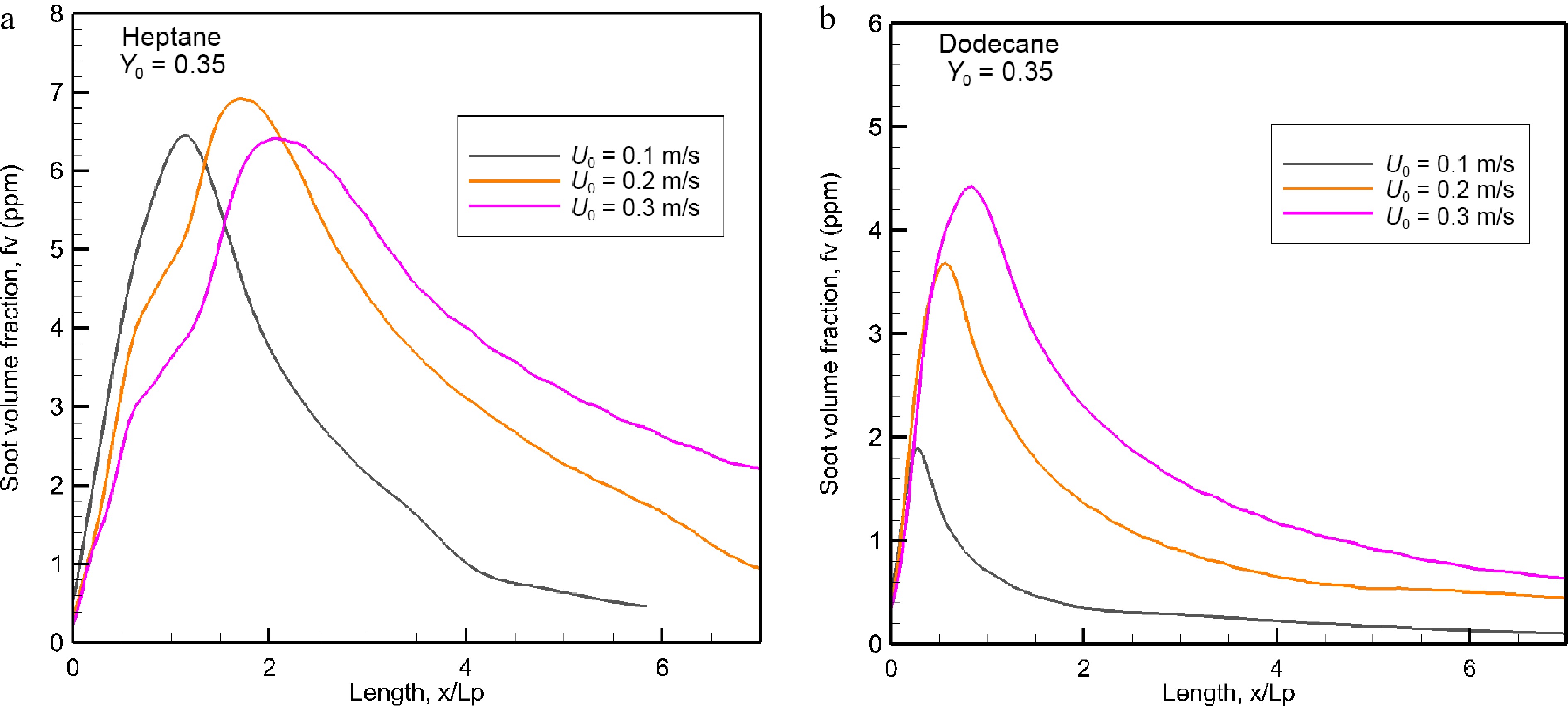
Figure 12.
Evolution of the mean value of soot volume fraction (ppm) in the windward direction as a function of oxidizer flow velocity.
$ \rm\overline F(x) = \int_{z = 0}^{z\max (x)} f (x,z)dz/Z\max (x) $ (10) where f is soot volume fraction, and Zmax (x) the thickness of soot layer so that f(x,z) = 0 for z > Zmax(x). As compared to the dodecane flame, the mean value of soot volume fraction for heptane is less sensitive to U0, with a peak of roughly 6.5 ppm due to limited oxidation processes. While as for dodecane flame, the peak in mean value of soot volume fraction increases by a factor of about 2.2 times with a rise of U0 from 0.1 to 0.3 m/s because its pyrolysis length, x/Lp, augments from 0.4 to 0.8 (cf. Fig. 5b). The location of the maximum soot formation moves away from the trailing edge of the pyrolysis zone (cf. Fig. 5) with an increase of U0. The soot volume fraction reaches a peak, and decays until almost complete absence beyond x/Lp = 6 only at U0 = 0.1 m/s. As compared to dodecane flame, the important soot layer (cf. Fig. 10) of heptane flame because of its strong burning rate (cf. Fig. 5a) results in an increase of the soot level in peak by a factor of 3.25, 1.8, and 1.4 times, respectively for U0 = 0.1, 0.2 and 0.3 m/s.
The removal of soot deposition onto wall surface is computed from its mass fraction, Ys, in a gas-phase cell adjacent to a wall, and thermophoretic velocity,
$ \,\mathop u\nolimits^{th} $ $\rm {{ m}}_{s}^{''}={{\displaystyle \rho Y_su}}_{}^{th}\Delta t\quad (kg/m^{2}) $ (11) Here,
$\rm u^{th} $ $\rm u^{th} = \dfrac{{K_{th}\mu }}{{\rho T_g}} \cdot grad(T) $ (12) As presented in Fig. 13a, a thick soot stratifications of heptane flame (cf. Fig. 10) conducts to an important soot deposition in a range of 0.6 to 1.18 g/m2 with an increase of U0 from 0.1 to 0.3 m/s. Such soot deposition will impact the visibility for egress and the time for smoke detectors to activate. The maximum soot deposition takes place beyond the pyrolysis zone of heptane, and however, in the pyrolysis zone of dodecane as shown in Fig. 13b, caused by the differences in burning rate and effective pyrolysis length (cf. Fig. 5). After the peak, soot deposition decays until almost complete absence starting from x/Lp = 4–6 for heptane flame, and from x/Lp = 2–4 for dodecane flame as a function of U0. As compared to dodecane flame, the peak in soot deposition for heptane flame increases by a factor of about 7.5 and 3 times with an increase of U0 from 0.1 to 0.3 m/s.
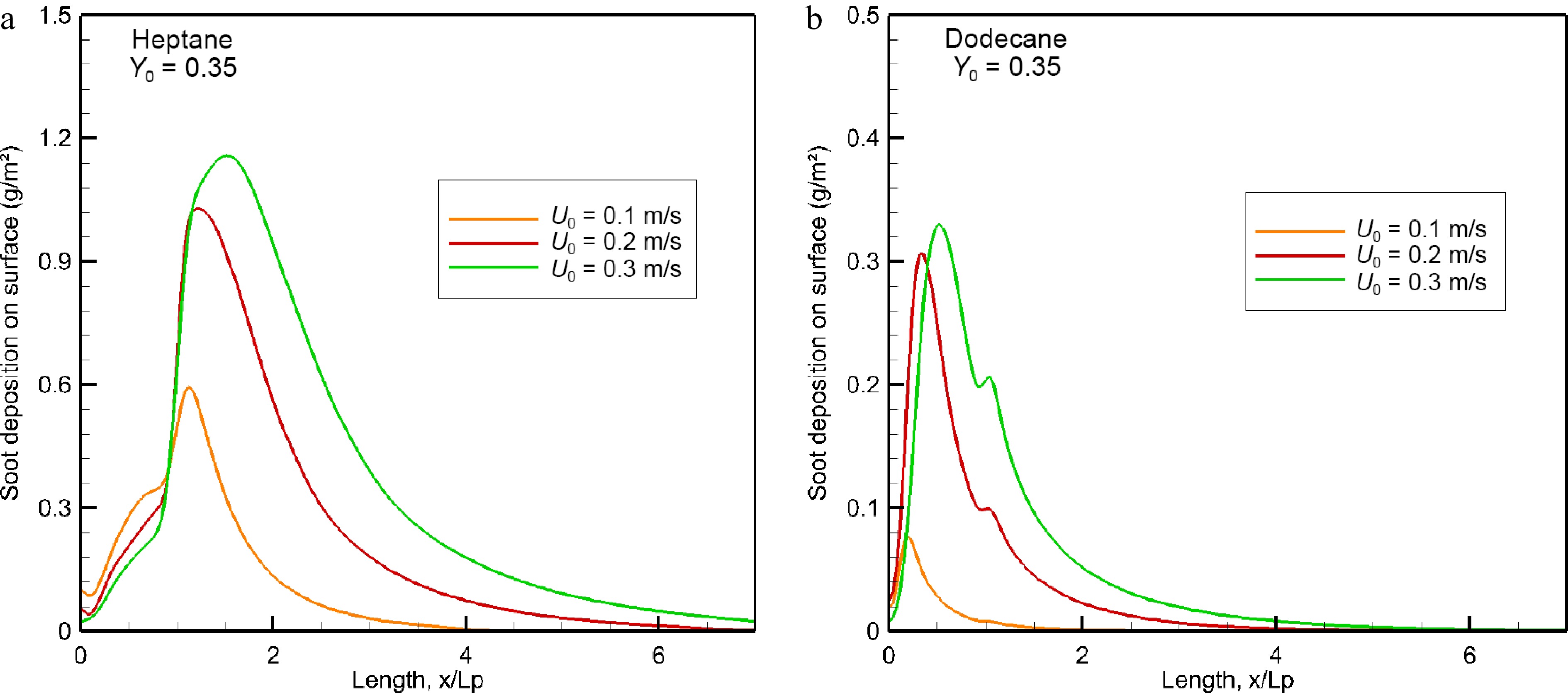
Figure 13.
Impact of oxidizer flow velocity on soot deposition (g/m2) over wall surface in the windward direction.
Figure 14 illustrates the computed fields of carbon monoxide on the axis of symmetry for the heptane and dodecane flames. Production of CO in abundance is mainly in the fuel-rich region over the pyrolysis zone, implying that its molar fraction appears to be approximately proportional to the oxygen depletion. The size of the region of higher CO volume fraction above 4 ppm of the heptane flame is roughly two times that of the dodecane flame due to stronger heptane burning rate (cf. Fig. 5). The CO molar fraction reaches a maximum of about 10% near the leading edge, even for the dodecane flame with a combustion efficiency higher than 0.9 (cf. Fig. 6b) due to its longer carbon chain.
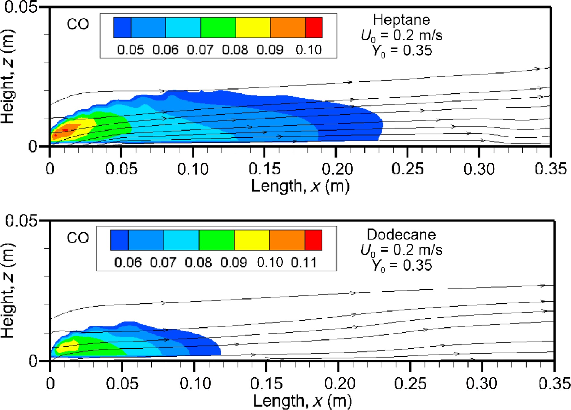
Figure 14.
Computed fields of CO volume fraction for heptane and dodecane flames at U0 = 0.2 m/s.
The influence of oxidizer flow velocity, U0, in a range of 0.1 to 0.3 m/s on the mean value (cf. Eqn 9) of CO volume fraction is evaluated in Fig. 15a & b in the windward direction for the heptane and dodecane flames. The curve represented in Fig.15 highlights clearly that CO volume fraction increases sharply in the pyrolysis zone to a peak which increases by a factor of about 50% by increasing oxidizer flow velocity from 0.1 to 0.3 m/s. This is mainly due to the fact that enhancement of burning rate (cf. Fig. 5) with U0 contributes to prevent fresh air entraining into the pyrolysis region, leading to a decrease of combustion efficiency (cf. Fig. 6b). The mean CO volume fraction appears practically insensitive to the fuel type. Although combustion efficiency of the dodecane flame is higher than 0.9 (cf. Fig. 6b), a peak in mean level of CO molar fraction reaches 4% near the leading edge as the heptane flame. Nevertheless, the forward layer of the dodecane flame at U0 = 0.3 m/s allows a quick decay of CO concentration below 1% downstream starting from x/Lp = 4 at which CO molar fraction of the heptane flame remains again above 3%.
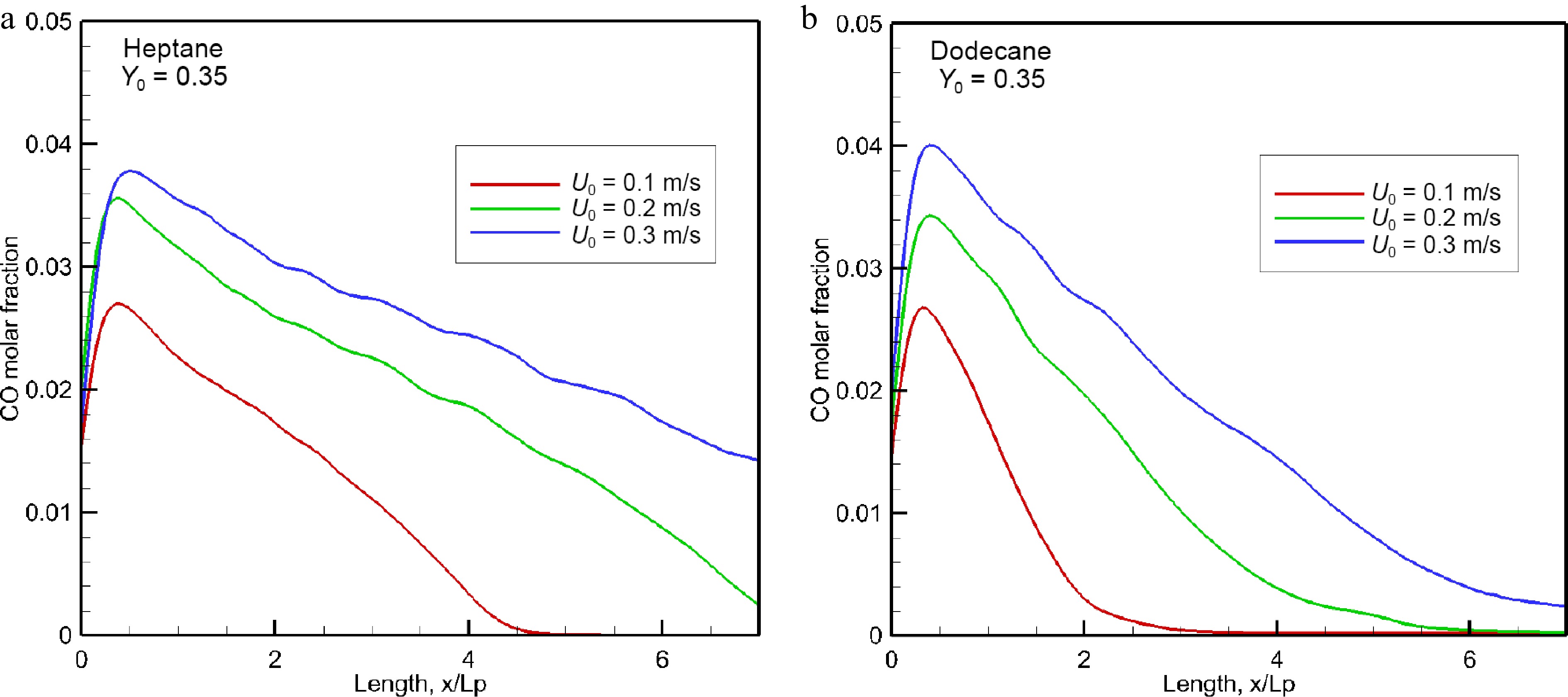
Figure 15.
Influence of oxidizer flow speed on the mean level of CO volume fraction in the forward direction.
Figure 16 depicts the unburnt hydrocarbons (CmHn) field at U0 = 0.2 m/s on the axis of symmetry for the heptane and dodecane flames. As indicated previously, a strong pyrolysis rate of heptane contributes to reduce the combustion efficiency (cf. Fig. 6b) due to incomplete reaction with a lack of oxygen, and the volume fraction of unburnt fuels reaches a peak of 30% over its pyrolysis zone. Obviously, a reduction in pyrolysis front length to x/Lp = 0.8 for dodecane flame (cf. Fig. 5b) allows an improvement of the mixing between oxygen and fuel with more incoming air flow, and this is evidenced by a reduction in volume fraction of unburnt hydrocarbon to about 14%.
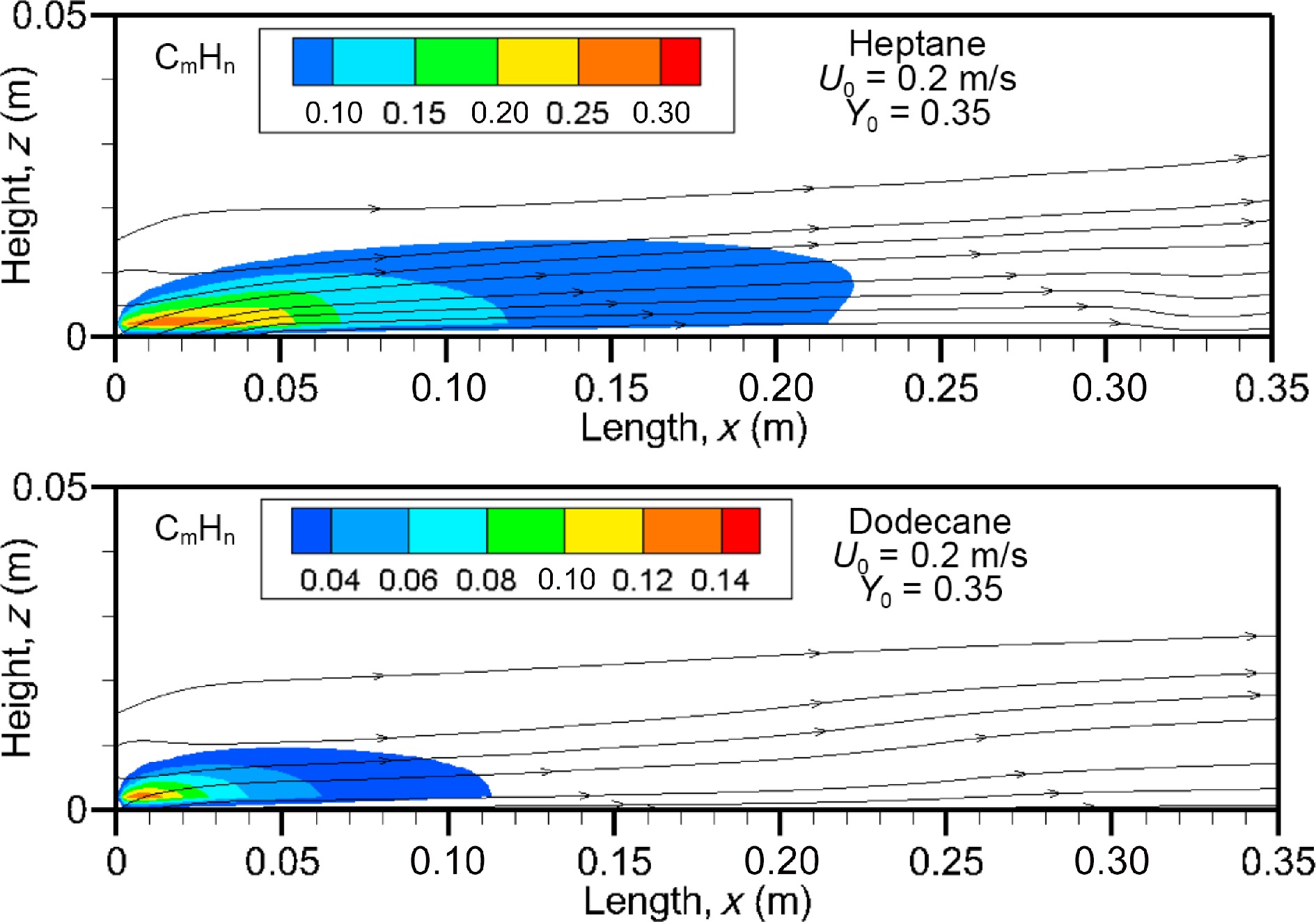
Figure 16.
Unburnt hydrocarbons field calculated at U0 = 0.2 m/s for heptane and dodecane flames.
The impact of an increase of oxidizer flow velocity from 0.1 to 0.2 upon the mean value of unburnt hydrocarbons volume fraction is also significant due to establishment of an oxygen-starved area in the boundary layer, as shown in Fig. 17a & b. As expected, a rapid growth of unburnt fuel takes place in the fuel rich part of the flame, reaching a peak depending on the fuel type and oxidizer flow velocity. The heptane flame exhibits a peak nearby the tailing edge at x/Lp = 1, which increase from 6% to 7.5% with an increase of Uo from 0.1 to 0.3 m/s. As compared to the heptane flame (cf. Fig. 17a), dodecane produces less unburnt fuel with a peak of about 3% (cf. Fig. 17b), and however, more CO (cf. Fig. 15b). Nevertheless, response of the peak in the mean volume fraction of unburnt fuel (cf. Eqn 5) is more sensitive to an increase of U0 from 0.1 to 0.2 m/s than from 0.2 to 0.3 m/s. The unburnt fuel from the dodecane flame can be practically suppressed downstream starting from x/Lp = 5 thanks to dilution inside a limited pyrolysis length (x/Lp < 0.8). While as the forward layer of heptane flame carries abundance of unburnt fuel downstream with a volume fraction of 2% up to x/Lp = 7 at U0 = 0.3 m/s.
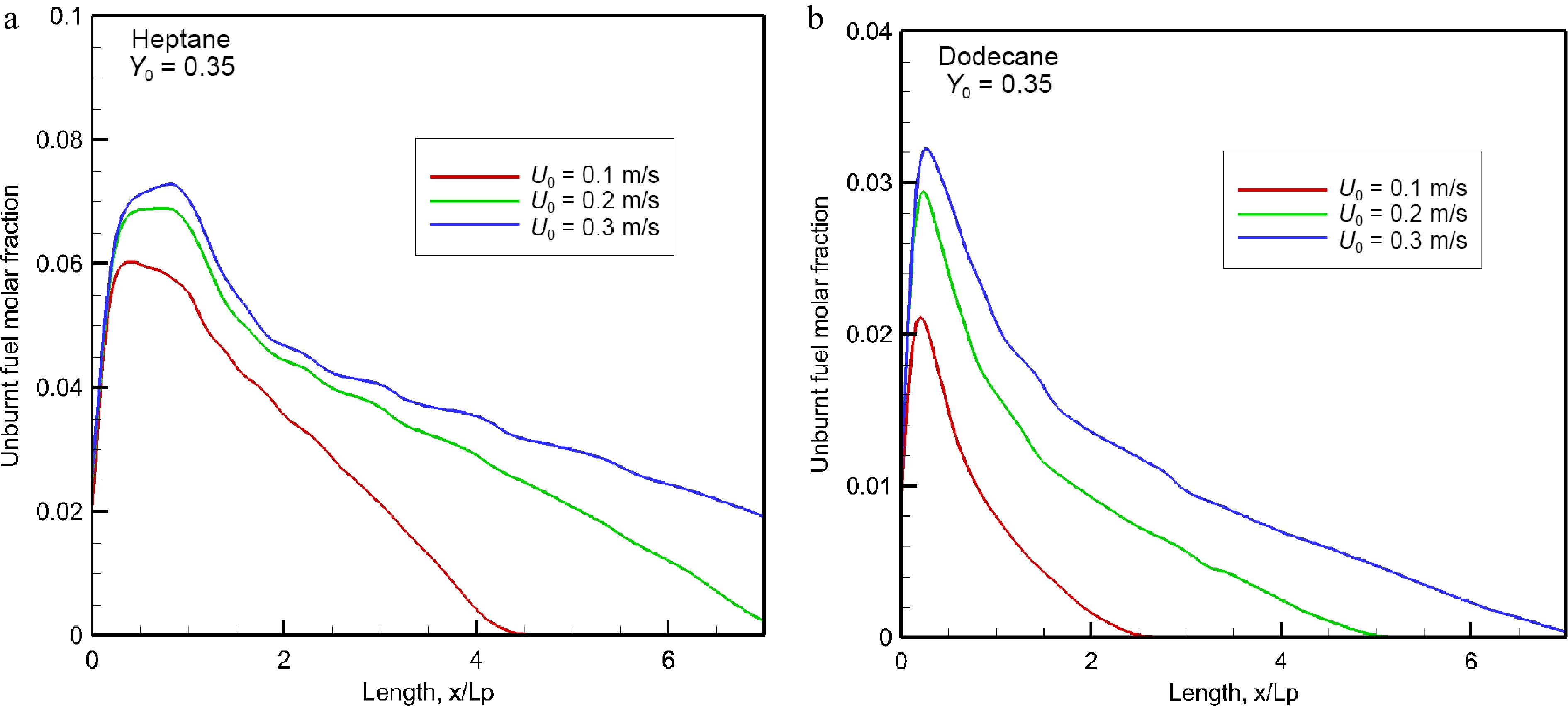
Figure 17.
Impact of oxidizer flow velocity on the mean concentration of unburnt hydrocarbons in the forward direction.
-
A set of numerical simulations is performed to investigate the impact of oxidizer flow speed on the molecular species composition of major toxic species, such as soot, CO and unburnt hydrocarbons from microgravity heptane and dodecane flames. The discrepancies between prediction and experiment are attributed to a combination of the experimental uncertainties and the capabilities of the physical model. In comparison with the experimental date, the uncertainty in the prediction of soot emission is estimated within 20-30% by taking into account a multitude of potential errors in the physical model via the semi-empirical parameters. However, any attempt to draw a general conclusion for quantifying the uncertainty and accuracy of the predicted toxic species is discouraged due to incomplete experimental database for a microgravity flame. From a general point of view, the present numerical study highlights clearly the impact of oxidizer flow speed in addition to liquid fuel type upon burning rate, flame behavior and its associated toxic species. Some major findings can be drawn as follows:
1) A dodecane flame at microgravity cannot support a sustained propagation of the pyrolysis front due to high boiling temperature of 216 °C. Its pyrolysis front length can increase from x/Lp = 0.4, 0.6 to 0.8 for a rise of oxidizer flow velocity from 0.1 to 0.3 m/s;
2) Heptane with a low boiling temperature needs less energy to generate sufficient volatiles for sustaining a flame propagation. Compared to dodecane flame, an increase in the flame length by a factor of 2.3 times is achieved;
3) The radiation fraction of the total heat flux over the pyrolysis surface reaches about 80% even for a small flame size due to enhanced soot emission;
4) Contrasted to the case with a fixed burning rate of microgravity flames, an increase of mainstream flow velocity induces an enhancement of soot production whatever the family of liquid hydrocarbons. The radiative loss fraction is higher than 0.5, and increases up to 0.7 with a high oxidizer flow velocity;
5) The size of the region of higher composition of major toxic species for the heptane flame is roughly four times that for the dodecane flame. Combustion efficiency of microgravity flames appears inversely proportional to oxidizer flow speed;
6) As a consequence of absence of the lateral entrainment by natural convection, peak volume fractions of major toxic species at microgravity increase by a factor of two times as compared to that at Earth gravity;
7) Regardless of oxidizer flow velocity, only about 15% of the combustion heat is supplied to sustain pyrolysis of the exposed liquid fuel due to a significant flame stand-off distance downstream.
Further investigations should be made to characterize accelerating flames which may happen occasionally due to a sudden supply in oxygen at a hidden area where major unburnt species can be accumulated in sufficient concentrations.
-
The authors confirm contribution to the paper as follows: investigation: Wang HY, Decamps N; writing, supervision: Wang HY; software: Decamps N. Both authors reviewed the results and approved the final version of the manuscript.
-
All data generated or analyzed during this study are included in this published article
This theoretical research is sponsored by the Agence Nationale de la Recherche (Projet no. ANR-18-EURE-0010).
-
The authors declare that they have no conflict of interest.
- Copyright: © 2024 by the author(s). Published by Maximum Academic Press on behalf of Nanjing Tech University. This article is an open access article distributed under Creative Commons Attribution License (CC BY 4.0), visit https://creativecommons.org/licenses/by/4.0/.
-
About this article
Cite this article
Wang HY, Decamps N. 2024. Influence of oxidizer flow speed on the toxic species composition in laminar diffusion flame under weightless conditions. Emergency Management Science and Technology 4: e010 doi: 10.48130/emst-0024-0008 

Influence of oxidizer flow speed on the toxic species composition in laminar diffusion flame under weightless conditions
- Received: 18 August 2023
- Revised: 29 February 2024
- Accepted: 18 March 2024
- Published online: 16 May 2024
Abstract: The molecular species composition of major toxic species, such as soot, CO and unburnt hydrocarbons from a boundary layer diffusion flame over heptane or dodecane surface at microgravity is numerically investigated. A two-step global reaction model for gas-phase chemistry and a simplified soot model consisting of laminar smoke point type for soot inception are used. Thermal radiation is calculated using the discrete-ordinates method coupled with a non-grey model for the radiative properties of CO, CO2, H2O and soot. The numerical results provide further insights into the intimate coupling between burning rate, flame length, thermal radiation, and toxic products at reduced gravity level. The importance of oxidizer flow speed to the flame structure, soot formation and thermal radiation at microgravity is demonstrated. The amount of soot from the microgravity heptane/dodecane flames augments with an increase of oxidizer flow velocity from 0.1 to 0.3 m/s due to an enhancement of burning rate. This finding is contrasted to the case with porous gas burners relative to toxic species production from microgravity flames. For the burning of various liquid fuels, the radiative loss fraction in general increase in a range of 0.5 to 0.7 due to enhanced soot formation with augmentation of the oxidizer flow velocity.