


-
Thermoplastic materials are characterized by light weight, easy processing, good thermal insulation performance, low price, etc., and are widely used in building exterior wall insulation materials, pipes, and floor curtain wall decoration materials. Among them, PMMA (Poly methyl methacrylate), a common thermoplastic with good transparency, optical properties, weather resistance, chemical resistance and hardness is widely used in daily life and high-tech industries[1]. The wide range of applications and good prospects of thermoplastic materials have led researchers around the world to invest great efforts in related research fields, but the lower glass transition temperature, pyrolysis temperature, and oxygen index, the larger calorific value of combustion and smoke production and other characteristics make the material a greater flame hazard. For example, the color steel plate with a core filled with thermoplastic insulation material is widely used in temporary rooms at construction sites for building projects because of its light weight, high strength, good heat preservation, and convenient installation. However, several flames have occurred in recent years due to combustible thermoplastics wrapped inside its steel plate sandwich.[2] In Henan, Lushan County (China) on May 2015, a particularly significant flame accident occurred, Kang Leyuan's elderly apartment room inside an electrical wiring failure, the flame quickly in the polystyrene material filled with color steel plate sandwich spread, resulting in a total of 39 deaths, six people were injured, as well as more than 20 million yuan of direct economic losses[3].
PMMA is a flame combustion field that commonly uses thermoplastic polymers. It has advantages of good combustion performance, complete combustion, low ignition temperature, slow burning speed, low carbonization, and good reproducibility[4], and its combustion and flame spread characteristics can represent real flame scenes. Shanghai's 'Technical Guidelines for Flame Barrier for External Wall Insulation of Buildings' stipulates[5] that the horizontal flame barrier for external wall insulation of buildings should not be less than 300 mm in height, and the vertical flame barrier should not be less than 200 mm wide, but the maximum width of the material in the specific construction has not been stipulated. In the actual flame scenario, the width of the material is an important factor affecting the spread of solid surface flame.
Tsai[6,7] and Jiang et al.[8−10] investigated the effect of specimen width on the spread of unilateral downstream flame, and the results showed that when the specimen width is less than the critical width, the rate of downstream flame spread increases with the increase of width, and when the specimen width is greater than the critical width, the effect of width effect on the spread of downstream flame is not obvious. For narrower specimens, the reduction of pyrolysis near the edge of the specimen is more obvious. Rangwala et al.[11] investigated the width effect in vertical downstream flame propagation and found that in laminar flame, the diffusion loss effect of pyrolysis gases to the two sides increases gradually with the increase of the width of the material and established a theoretical model. Gollner et al.[12] investigated the behavioral patterns of corrugated paper in the early stage of vertical downstream flame propagation and found that the pyrolysis front loss effect is gradually enhanced with the increase of the width of the material. Leventon et al.[13] measured the thermal feedback of PMMA samples of different heights in the process of vertical flame spreading, and found that the total heat flow of the bottom of the fuel was much larger than that of the upper part due to the laminar flame at the bottom position of the flame spreading stationary distance being much smaller. Jiang et al.[8] carried out experiments in vertical downstream flame spreading on PMMA and investigated the sample width effect and developed a global mass loss rate prediction model with coupled fuel width based on Emmons' assumption[14].
From the above studies, it can be seen that the current research on the width effect on flame-spreading behavior mostly focuses on the study of downstream continuous flame spreading, while in fact in real life, most of the materials are in a non-continuous state and there is no definitive conclusion on the effect of width on flame spreading. Combined with a previous study[15], in the discrete flame spread rate research process with combustible material coverage of 62.55%, the flame height and mass loss rate have reached the peak of the conclusion, this paper selects the discrete state of the solid size of a height of 6 cm and 4 cm of air spacing length, the conditions of the fuel coverage of 60%, can maximize the acceleration of flame propagation. By selecting discrete PMMA sizes with different widths, how the flame growth phase and flame stabilization phase of discrete flame propagation are affected by the width of the material in open space is analyzed.
This paper aims to investigate the characteristics of flame spread on the surface of PMMA under varying widths, providing an in-depth analysis of the influence of material width on the mechanism of flame spread on discretely distributed solid surfaces. This not only advances the fundamental research on the evolution of fire behavior in discrete solid distributions but also offers significant guidance for fire prevention design and firefighting strategies in scenarios such as building exterior insulation fires.
-
Investigating the vertical flame spread process of discrete polymethyl methacrylate (PMMA) involved a series of experiments conducted under controlled indoor conditions, including ambient temperature and the absence of wind. The objective was to explore the influence of confined space on flame spread characteristics across different widths. This study focused on comprehending the flame spread mechanism through close observation, documentation of experimental phenomena, and analyzing flame parameters during growth and stabilization.
A comprehensive experimental system, depicted in Fig. 1, comprised a specimen fixation device and a data acquisition device. A green fireproof cloth served as a background curtain to enhance flame morphology clarity and ensure experimental safety. The camera used was the XT-3 model, featuring a magnification of 0.75 times, a display delay of 0.005 s, and a refresh rate of approximately 100 frames per second (fps). Flame characteristics were assessed by decomposing the video footage into frame-by-frame grayscale images, and the brightness value of each pixel was calculated using Matlab. A suitable grayscale threshold was set to distinguish between flame and non-flame areas.
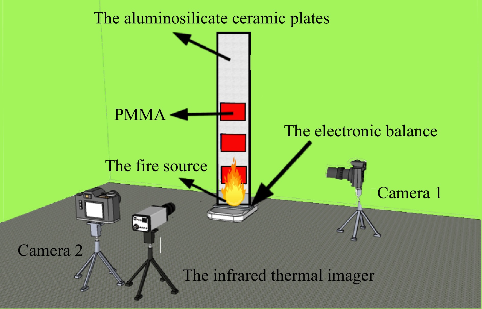
Figure 1.
Experimental apparatus.
In the experiment, the PMMA sample was positioned above the base and ignited using a DREMEL 2200-4 multi-function gas burner, which initiated spontaneous combustion of the PMMA array. To mitigate the influence of heat from the igniter on the fuel array, a fire-retardant board measuring 30 cm long, 10 cm wide, and 2 cm thick was employed as a baffle. This setup effectively blocked the upward transfer of external heat during the ignition process, ensuring that the observed effects were solely attributable to the material properties of the PMMA.
The mass sensor utilized was the ES-30001TS model, capable of measuring up to 30 kg with a precision of 0.1 g. The thermal imager employed was the MAG30 model, operating within a measurement wavelength range of 7.5 to 14 μm, featuring a pixel size of 17 μm. The acquisition frame rate was set at 50 Hz, while the output frame rate was maintained at 25 Hz.
This paper employs a vertical flame spread system to simulate the flame propagation process on a discretely distributed solid surface, as illustrated in Fig. 2. The system consists of a base and a fire-resistant backplane. The base securely positions the fire backing plate perpendicular to the ground, while the fire-resistant backplane accommodates discrete material blocks made of aluminosilicate ceramic plates known for their low thermal conductivity, high stability, and corrosion resistance. The dimensions of the fire-resistant backplane used in this study are 50 cm × 15 cm × 2 cm.
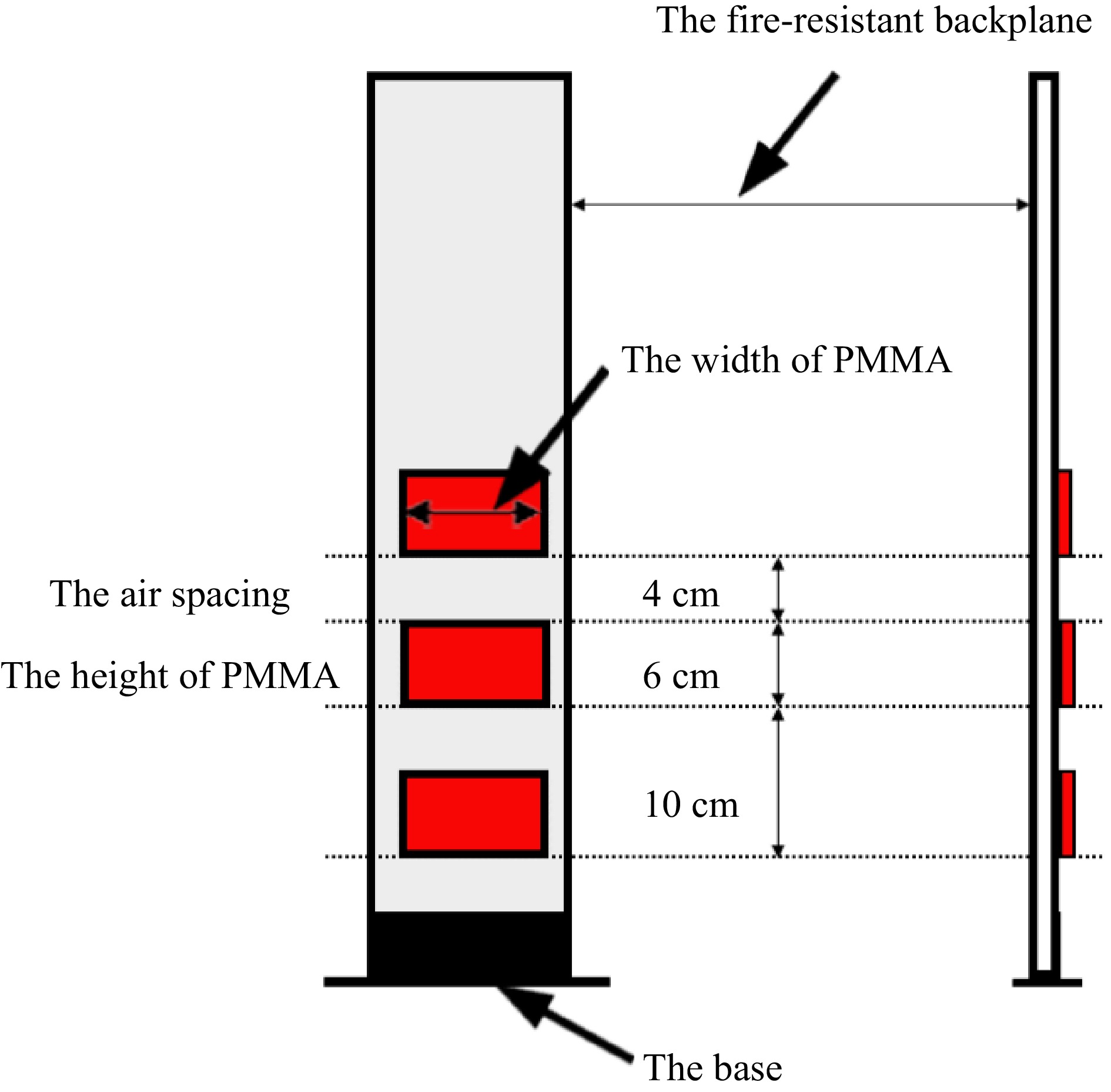
Figure 2.
Experimental device for PMMA.
In this study, a discrete PMMA block measuring 6 cm in height, with an air spacing of 4 cm and a thickness of 1 cm, was selected as the specimen to examine the effects of different specimen widths and restricted distances. Furthermore, considering the thermal penetration thickness of PMMA is only 0.2 cm, while the specimen thickness employed in this study is 1 cm, the material can be regarded as thermally thick. Lastly, a silicone-free high-temperature sealant was used to affix the PMMA block onto the fire-resistant backplane, composed of a polymer material exhibiting excellent elasticity, adhesion, sealing properties, as well as remarkable resistance to high temperatures, making it suitable for long-term use below 800 °C and fire resistance up to 1,280 °C.
PMMA single sample height and air spacing distance are fixed, respectively, 6 cm and 4 cm, the width of the specimen is selected as a range of 5−10 cm, and a total of 18 conditions are designed, as shown in Table 1, to facilitate experimental comparisons, the specimen in a single piece, two pieces, and three pieces, respectively, correspond to the letters A, B, and C. For the sake of experimental comparison, the single block, two blocks and three blocks in the specimen correspond to the letters A, B and C, respectively, and the numbers behind the letters represent the corresponding widths of conditions (cm). To ensure the repeatability and validity of the experiment, at least three experiments were repeated under each condition.
Table 1. Table of conditions for discrete solids of different widths.
Width (cm) 5 6 7 8 9 10 Single piece of PMMA A-5 A-6 A-7 A-8 A-9 A-10 Two pieces of PMMA B-5 B-6 B-7 B-8 B-9 B-10 Three pieces of PMMA C-5 C-6 C-7 C-8 C-9 C-10 -
Flame morphology is a visual parameter that reflects the flame propagation process. In this section, discrete flame propagation characteristics and the effect of material width on flame morphology in open spaces will be analyzed based on frontal and lateral flame morphology diagrams.
Width affects flame morphology
-
A schematic diagram of the stable combustion stage of a single PMMA sheet under different width conditions is shown in Fig. 3. As can be seen from the figure, with the increase in the width of the material, the flame-burning area increases, and the flame width also increases. In comparative analysis, the latter three diagrams consistently demonstrate markedly greater flame brightness than the initial trio. This observation is primarily attributable to the wider widths of the specimens tested, which increase the combustion area. As a result, there is a corresponding uptick in the release of flammable gases, intensifying the combustion process. Consequently, flames from broader specimens exhibit a heightened luminosity relative to those from narrower counterparts.
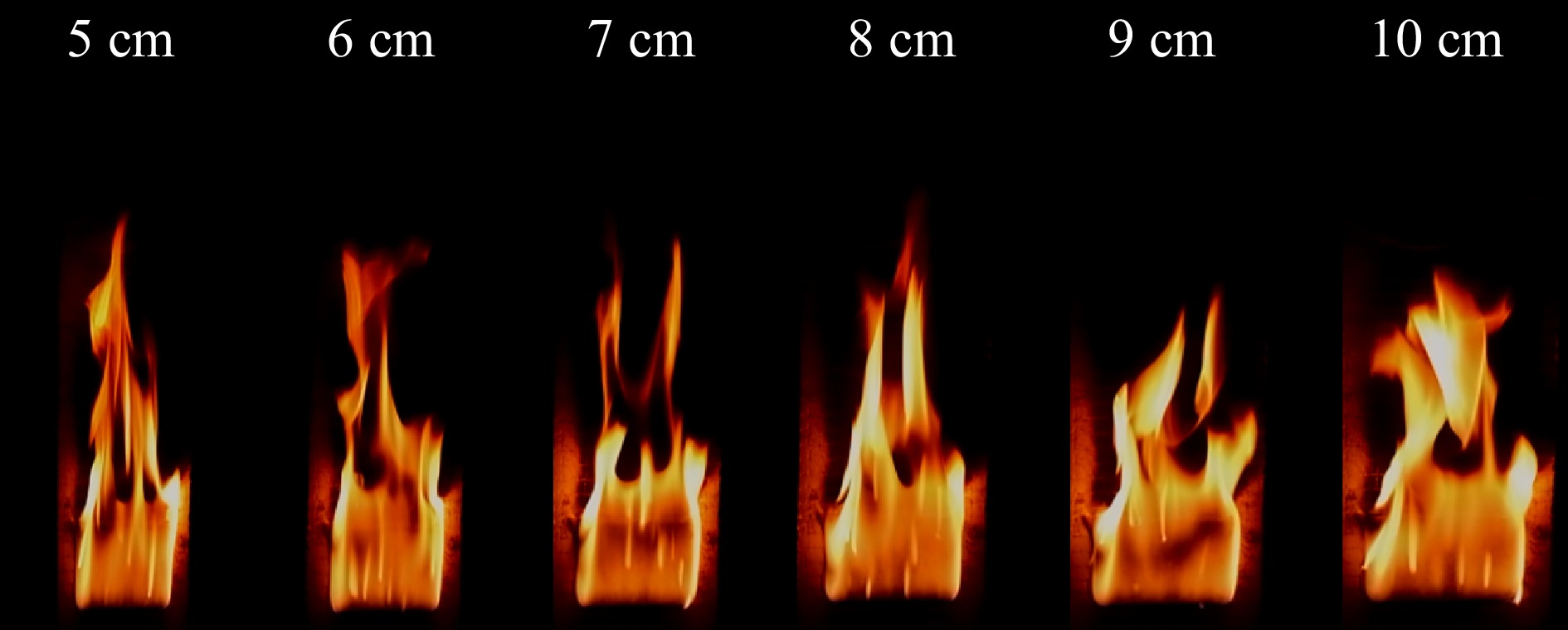
Figure 3.
Schematic diagram of the front side of a single piece of PMMA burning with different widths.
Figure 4 shows the front view of the stabilized combustion stage of two PMMA plates under different widths. It can be seen that under different fuel widths, the discrete fuels all present roughly the same flame morphology during the stable combustion process: the flame presents stable laminar combustion on the surface of the first PMMA plate; turbulent combustion on the surface of the second PMMA plate, and the flame presents a more violent pulsation phenomenon and intermittent phenomenon above the material, which is due to the flame body of the second PMMA is subject to the first PMMA plate burning flame body's buoyancy drive and flame superposition, resulting in the flame body shaking violently.
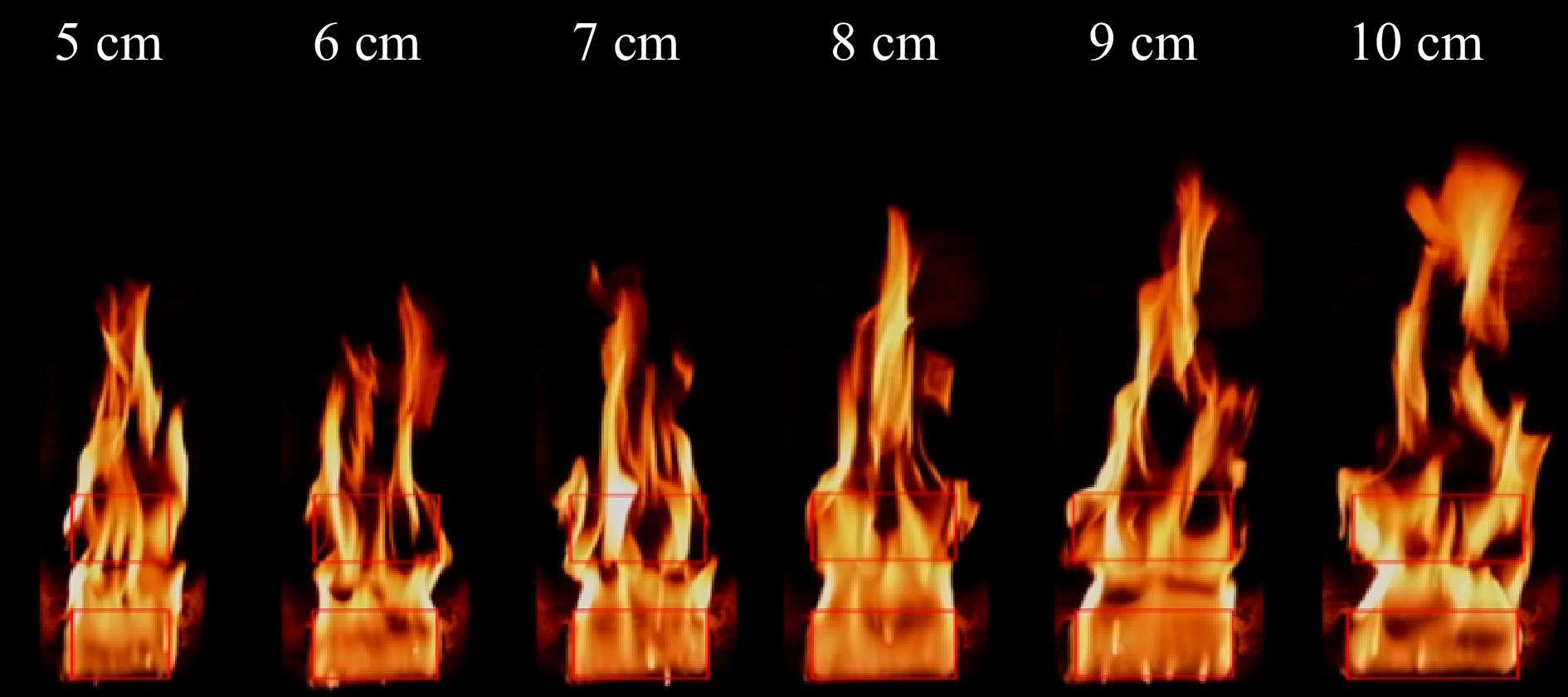
Figure 4.
Schematic diagram of the burning front side of two pieces of PMMA with different widths.
At the same time, in the frontal schematic, the flames in the material air spacing all present a concave tendency from both sides to the middle, which is because the flame front presents an inverted V tendency in the process of the flame burning uniformly, which is the same flame morphology as that presented by the flame front above the second piece. That is to say, the discrete flame spreads are roughly the same in longitudinal morphology and the differences are in the transverse flame width and flame brightness, the wider the width, the greater the flame brightness.
Figure 5 shows the front view of the stable combustion of three PMMA plates under different widths. It can be seen that the three PMMA plate's combustion presents the same law with single and two PMMA plates, i.e., the flame width increases with the increase of the fuel width, and the flame tends to converge from the two sides to the center at the air spacing, which is consistent with the inverted V shape presented by the flame front. Meanwhile, it is the same as the schematic diagram of the front of the two PMMA panels, i.e., the first PMMA panel presents a stable laminar flow combustion state, while the first and second PMMA panels are affected by the bottom flame buoyancy drive and the flames present obvious jittering and intermittent phenomena.
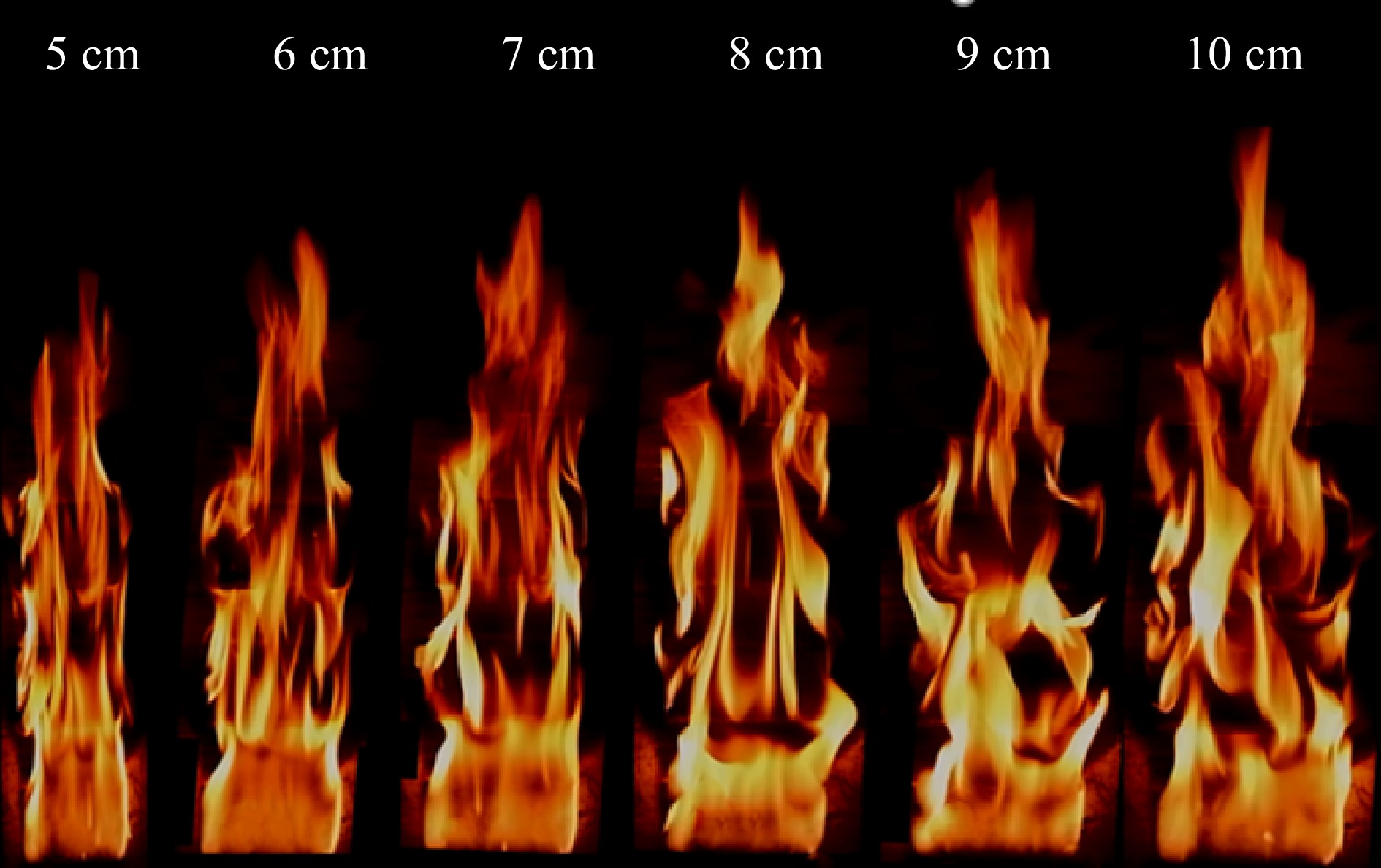
Figure 5.
Schematic diagram of the burning front side of three PMMA plates with different widths.
Comprehensive analysis
-
According to the above flame pattern, when the flame spreads on the discrete distribution solid surface, the flame shows stable laminar combustion in the A layer, and B and C layers are subjected to violent flame jitter and intermittent phenomenon at the bottom and show the tendency to concave from both sides to the middle in the frontal air spacing, and the flame peak shows obvious inverted V phenomenon as shown in the frontal schematic diagram. The flame shows the tendency to concave inward in the air spacing and shows wall-to-wall phenomena in the air spacing and the upper part of the wall.
The flame shows a tendency of inward concavity at the air interval and wall sticking phenomenon at the air interval and the upper part of the wall, while the flame thickness at the effective solid surface shows a tendency to increase from the bottom to the upper part of the flame, as shown in the side schematic diagrams. Under different widths, the flame pattern in the discrete distribution of the solid surface shows the same pattern, but the flame pattern in the direction of the width of the difference is more obvious, the strongest contrast is the 5 and 10 cm width of the conditions, the larger the width, the more fully pyrolyzed the material, the flame brightness is brighter. At the same time, the flame in different conditions shows the thickness in the center line is larger than the two sides of the characteristics, this is because part of the combustion vapors to the material on both sides of the diffusion of the flame width is greater than the width of the sample, and the phenomenon from the center line to the two sides of the decreasing step by step.
For a solid that is burning, to effectively explain the heat and mass transfer process between the solid and the airflow flowing over the solid surface, according to the flame spreading pattern process, Cai[16] established the concept of the boundary layer on the surface of solid materials to divide the boundary layer into three layers: velocity boundary layer, thermal boundary layer, and concentration boundary layer.
Figure 6 shows a schematic diagram of the continuous and discrete concentration boundary layer. As can be seen from the figure: for continuous solids, the thermal decomposition of solids to generate combustible gases driven by buoyancy to form a concentration boundary layer, with continuous development of the pyrolysis front, the thickness of the concentration boundary layer is also gradually increased in the formation of a concentration gradient on the surface of solids in the fluid region; for discrete solids, the concentration boundary layer in the air interval at the inward trend of depression, which is due to the absence of pyrolysis gases generated at the air interval, and this is because no pyrolysis gas is generated at the air gap, and the pyrolysis gas generated by the combustion of the lower material plate is entrained by the air at the gap, resulting in the phenomenon that the overall concentration thickness decreases.
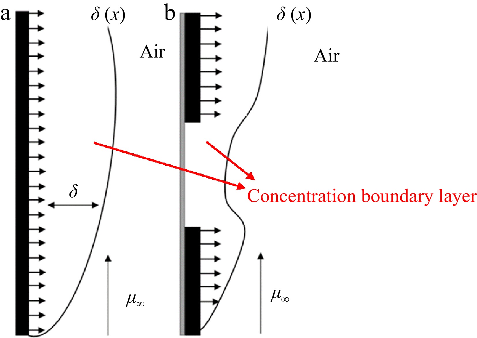
Figure 6.
Concentration boundary layer (a) continuous, and (b) discontinuous.
Analysis of the influence of width on the stability stage of discrete flame spread
-
In this section, experimental samples of different widths are set up and the parameters of flame height, mass loss rate, and heat release rate are analyzed. By processing and fitting the experimental data, the relationship between the parameters in the stabilization stage with width is derived.
Flame height
-
The study of the flame height in the stable stage is of great significance to the discrete flame-spreading behavior. Since the solid material shows turbulence after complete combustion in the experimental process, the fluctuation is large, so this paper selects the average value of the flame height of the stable combustion stage of the material as the flame height in this experiment.
Figure 7 shows a schematic diagram of the flame height under different working conditions. As can be seen from the figure, in the initial stage of combustion of the material, the flame height is small, and the flame moves up and down more gently, with the continued development of the flame, the flame burns sufficiently, the flame height shows a stabilizing trend, the flame height fluctuates up and down within the average value, which tends to stabilize the situation. This is mainly because: in the initial stage of combustion, due to the flame pyrolysis area being small, the PMMA plate pyrolysis gas release is small, the combustion is not sufficient, so the flame height is small; with the rise of the flame top, the unburned area of more material being heated causes the release of flammable gases, when the material is uniformly burned, pyrolysis release of gases tends to stabilize the rate of loss of quality of the material stabilized at this time and the flame height change tends to stabilize.
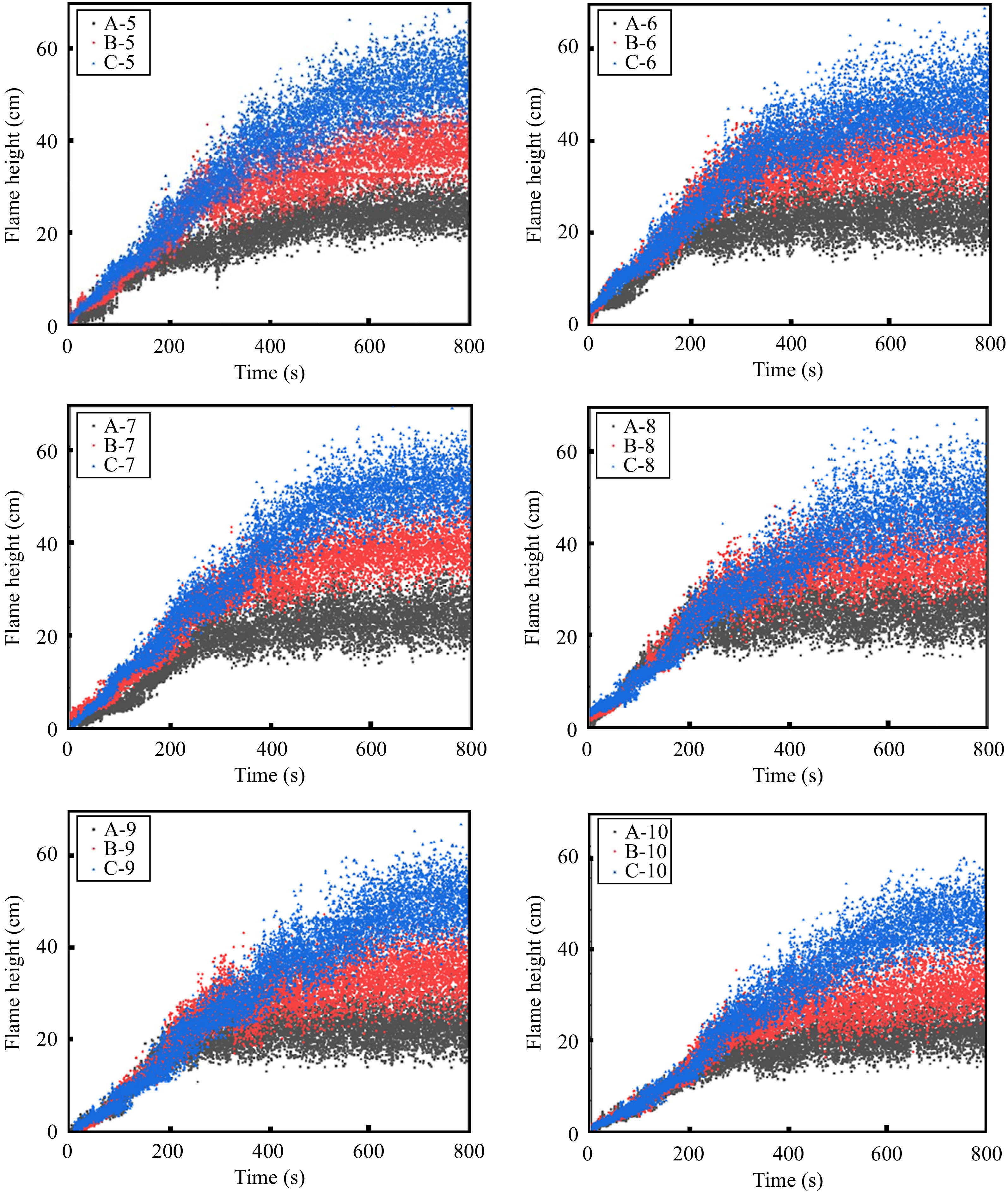
Figure 7.
Schematic diagram of flame height at the steady stage.
From Fig. 7, the average height of the flame, and the average height of conditions A-5, A-6, A-7, A-8, A-9, and A-10 are 25.46, 25.60, 27.24, 29.31, 30.63, and 32.85 cm, respectively. From the section on flame morphology, the first layer of the PMMA plate combustion at the bottom of the combustion presents laminar combustion and combustion stability, in the upper part of the flame due to the bottom flame buoyancy dominated by a turbulent state. Combustion is stable, in the upper part of the flame due to the bottom flame buoyancy dominated by the turbulence state, it is known from the flame height that the width effects in the combustion of the first PMMA plate is more obvious, i.e., the larger the width, the higher the flame height. The flame heights of conditions B-5, B-6, B-7, B-8, B-9, and B-10 are 40.17, 42.26, 43.81, 45.19, 46.73, and 47.18 cm, and from the data, it can be seen that the larger the width, the higher the flame height, and the difference between the flame heights of the conditions with 5 and 10 cm widths is further increased by the presence of the air spacing. further becomes larger. This means that the effect of the presence of air spacing on the width is more pronounced. The flame heights for conditions C-5, C-6, C-7, C-8, C-9 and C-10 are 54.83, 56.18, 59.83, 63.17, 65.86, and 68.86 cm. This further proves that the presence of an air spacer further increases the width effect. Combined with the change of pyrolysis front position and flame spreading speed in the previous section, it can be seen that although the speed of the 6 cm width flame will be reduced during the spreading process, the height of the flame stabilization stage will be greater than that of the 5 cm width specimen when the material is fully burned. Therefore, the larger the width, the higher the flame height in the stabilization stage.
The average flame height during the stabilization phase was plotted as shown in Fig. 8.
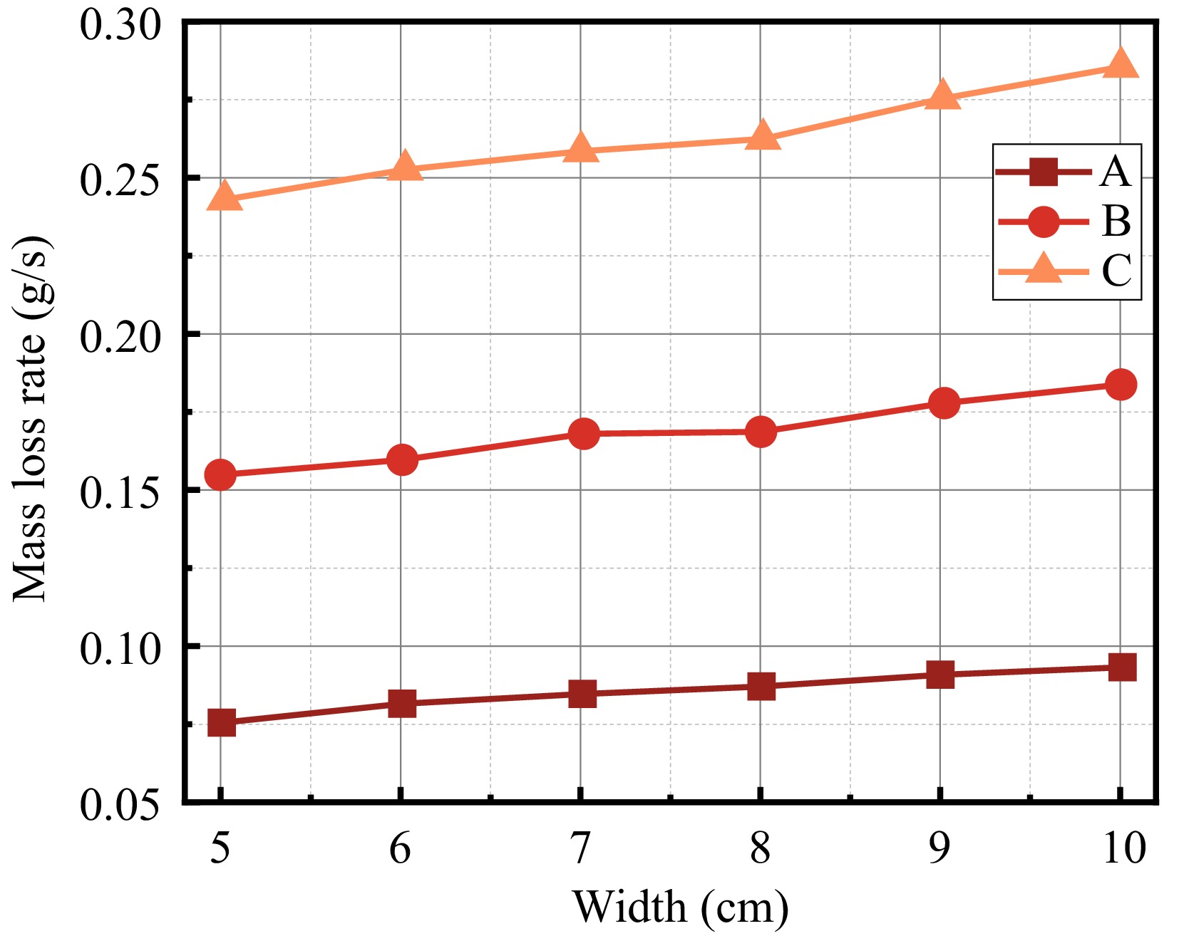
Figure 8.
The relationship between average flame height and width.
Dimensionless flame height is the ratio of the average flame height to the width of the material (H/W)[17]. In the width effect, the dimensionless flame height decreases with increasing specimen width. The diffusion flame height is mainly determined by the buoyancy and inertia forces, and a dimensionless number, the Froude number is usually introduced to describe the magnitude relationship between the buoyancy and inertia forces, defining the Froude number as:
$ Fr={u}_{0}^{2}/Wg $ $ {H}_{f}/W~F{r}^{n} $ $ {H}_{f}/W\sim {W}^{-n} $ (1) An et al.[18] obtained 0.7 < n < 0.9; Zhang et al.[19] obtained 1/5 < n < 1/3. After converting the above obtained average flame height to dimensionless flame height, the relationship between the width and dimensionless flame height is plotted in Fig. 9, and the image is fitted by applying Eqn (1). It can be seen that the dimensionless flame height is well fitted to the width of the specimen, and with the increase of the width, the dimensionless flame height shows the tendency to decay as a negative power law, which is shown from the figure that the value of n ranges from 0.6 to 0.8. In general, the width effect still exists with the increase in the number of discrete blocks, and the more the number of blocks is, the more obvious the tendency to decrease is 0.6~0.8. In general, with the increase of the number of discrete blocks, the width effect still exists, and the more the number of blocks, the more obvious the trend of decreasing dimensionless flame height.
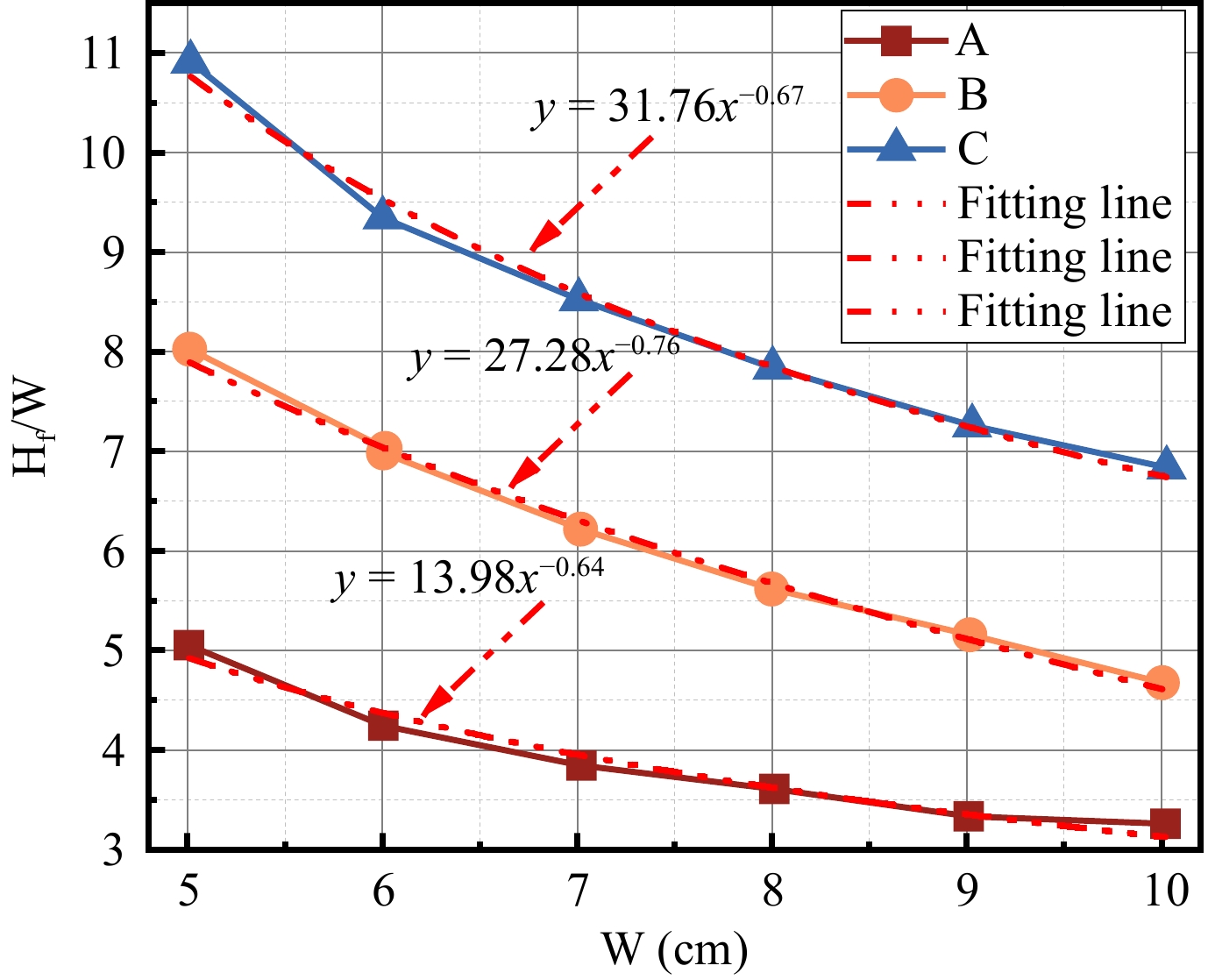
Figure 9.
The relationship between dimensionless flame height and sample width.
Rate of mass loss
-
The material mass loss rate in the stabilization stage can be obtained by the first-order derivation of the mass loss curve. However, in the experimental process, the data acquisition time of the computer is smaller than the response time of the mass sensor, which leads to large noise interference in the process of deriving the mass loss curve, so it is necessary to filter the mass loss rate curve to get a smoother curve. Take the C-10 condition as an example, draw the mass loss rate processing diagram, as shown in Fig. 10, and do the mean value processing for the mass loss rate in the stabilization stage to get the average mass loss rate at the stabilization moment is 0.286 g/s.
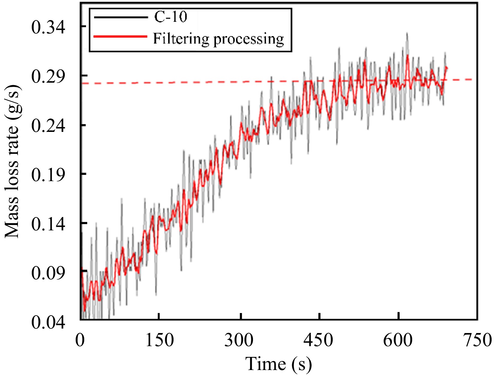
Figure 10.
C-10 Mass loss rate processing diagram.
Equivalent treatment as described above for the other conditions yields the instantaneous mass loss rate at the moment of the stabilization phase as shown in Table 2.
Table 2. Rate of material mass loss (g/s).
Conditions Height 5 6 7 8 9 10 A 0.076 0.082 0.085 0.087 0.091 0.093 B 0.155 0.160 0.169 0.170 0.179 0.184 C 0.243 0.253 0.260 0.263 0.276 0.286 Table 3. Physical parameters of PMMA in Eqn (2)[8].
Parameters Characteristic Numerical value $ B $ Atomic weight of an element 1.32 $ {c}_{p} $ Specific heat capacity 1.207 kJ/(kg-K) $ {k}_{w} $ Heat conductivity 0.091 W/(m-K) $ Pr $ Prandtl (math.) 0.073 $ {T}_{f} $ Flame temperature 1,400 K $ {T}_{p} $ Pyrolysis temperature 623 K $ \alpha $ Thermal diffusivity 168 × 10 m−62 /s $ v $ Kinematic viscosity 121 × 10 m−62 /s The mass loss rate vs sample width is shown in Fig. 11, and the results are all for the flame in the stabilization phase, as shown in Fig. 10 after 450 s. The mass loss rate is the average value of the curve. For the same conditions, the mass loss rate shows an increasing trend with the increase of the sample width, which is because the increase of the sample width increases the area of the flame of the material in contact with the air, increasing the mass loss rate. Jiang et al.[8] summarized the mass loss rate
$ {\dot{m}}_{f} $ 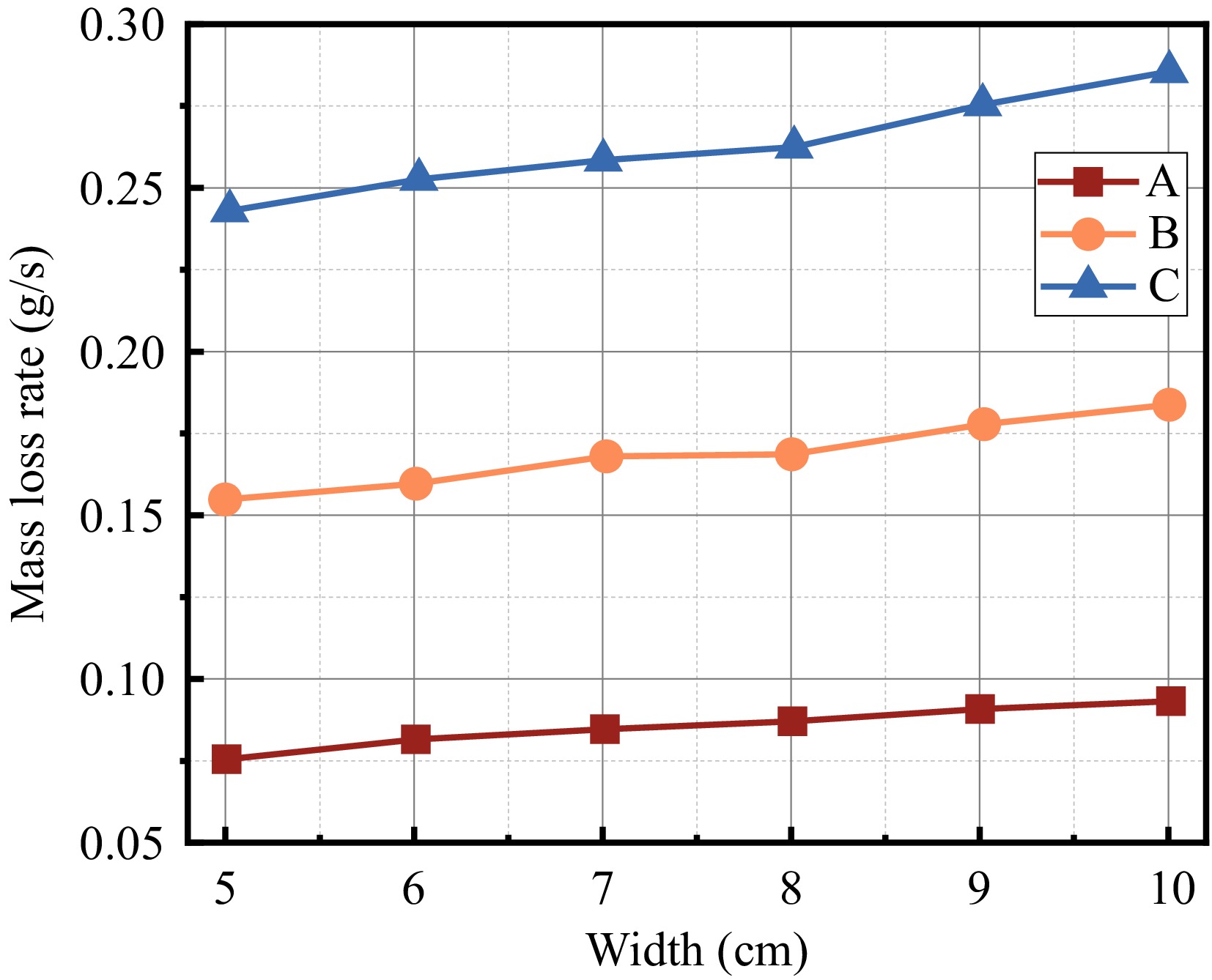
Figure 11.
The relationship between mass loss rate and width.
${\dot{m}}_{f}=\dfrac{B{k}_{w}S}{{c}_{p}D}{\left\{0.825+\dfrac{0.387R{a}_{L}^{1/6}}{{\left[1+{\left(0.492/Pr\right)}^{9/16}\right]}^{8/27}}\right\}}^{2} $ (2) In addition to what is in the Table 3, the Ra Reynolds number[20] in the above equation can be expressed as:
$ R{a}_{L}=\dfrac{g\beta \left({T}_{f}-{T}_{\infty }\right){D}^{3}}{v\alpha } $ (3) $\, \beta $ $ S_{total}=3\ \times\ \left(WL+2TL+2TW\right) $ (4) In the above equation, the Stotal is the area of the solid surface region, and W is the width of the material, and T is the material thickness, and L is the material length, as shown in Fig. 12.
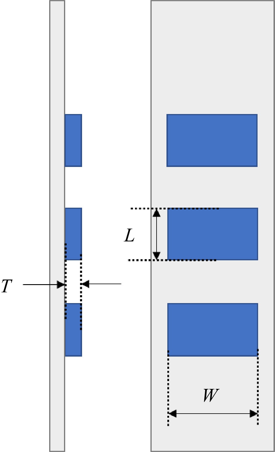
Figure 12.
Schematic diagram of solid area parameters.
In the field of flame, for irregular fuel shapes, it is common to use a characteristic length transformation method to evaluate the flame dynamics behavior. The most commonly used method is the equivalent diameter method. This method typically converts rectangular and other irregularly shaped fuels to the equivalent diameter of a circle. However, this method is only applicable to conditions that have approximately the same length and width. The length of the material in this experiment is much larger than the width, so the equivalent diameter method is not applicable. The method of combining previous definitions of force diameters is used to solve the problem of irregular fuel shapes[21,22]:
$ D=2L\left(W+2T\right)/L+W+2T $ (5) Substituting the above equations, we can find the
$ {\dot{m}}_{f} $ $ \dot{m} $ 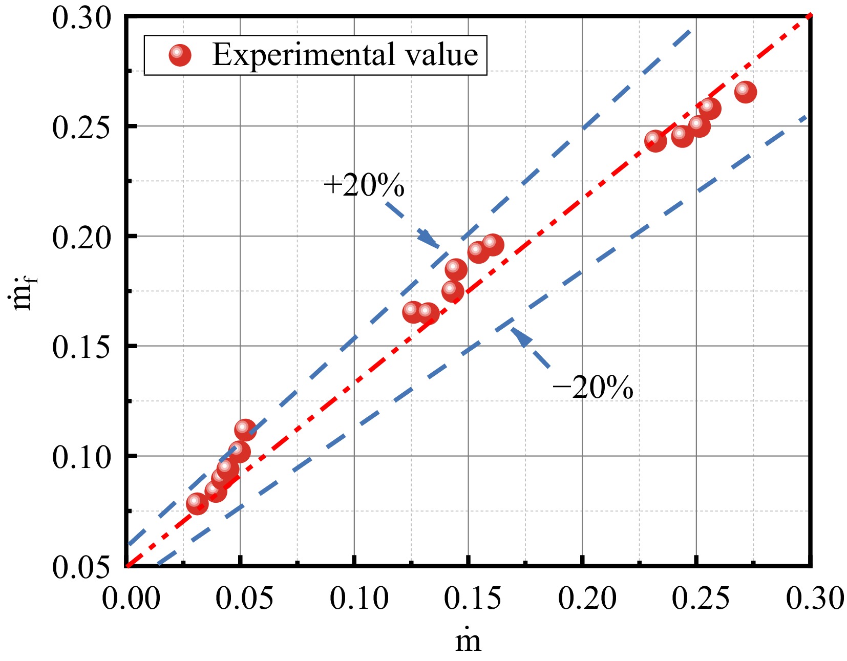
Figure 13.
Comparison of predicted mass loss rate data with experimental data.
Rate of heat release
-
Width effects on flame spread include lateral diffusion of gaseous fuels, heat loss, and air entrainment. To better compare width effects on the discrete flame spread, this section focuses on analyzing the unit width heat release rate
$ \dot{Q} $ $ \dot{Q} $ $ \dot{Q}=\left(\dot{m}/w\right)\Delta {H}_{c} $ (6) In the above equation,
$ \dot{m} $ $ \mathrm{\Delta }{H}_{c} $ $ \dot{Q} $ $ \dot{Q}\sim{W}^{n} $ As can be seen from Fig. 14, the effect of width on the heat release rate shows approximately the same pattern as the effect of width on the average flame height in the previous section, i.e., the heat release rate decreases with increasing width in a negative power law relationship. Laterally, for increasing width, the heat release rate
$ \dot{Q} $ 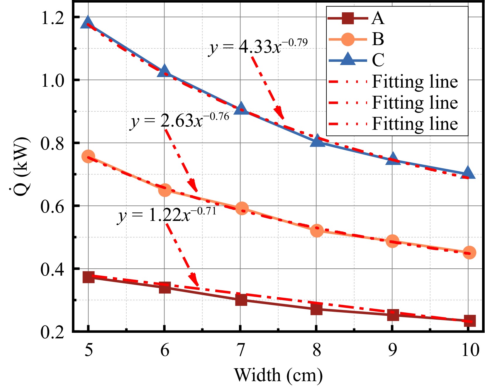
Figure 14.
The relationship between heat release rate and width.
Theoretical analysis of material width in open space and discrete flame spread
-
Rangwala et al.[11] and Pizzo et al.[24] The theory proved by the study focuses on the laminar flame without sidewalls (width of 200 mm), which has relatively large pyrolysis products and heat loss around the sidewalls. Rangawala et al.[11] combined mathematical models and experimental results to analyze the effect of finite width on the flame-spreading tendency, and established a simplified physical model of laminar flames, as shown in Fig. 15. In Fig. 15, the X-axis is the direction of the flame spread, the Y-axis is the direction of flame thickness on the surface of the material, the Z-axis is the direction of the width of the material, the
$ {\dot{m}'}_{f}\left(x\right) $ $ {\dot{m}'}_{z}\left(x\right) $ $ {X}_{p} $ $ {\delta }_{f} $ 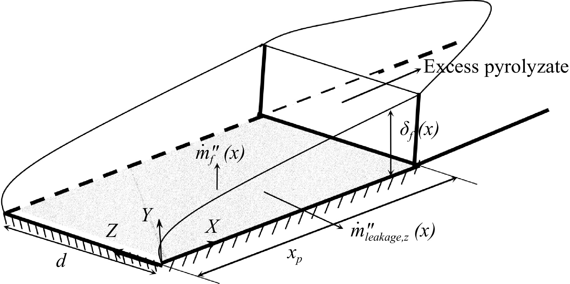
Figure 15.
Physical model of width-influenced flame spread[24].
Rangawala et al.[11], through theoretical analysis, has made the following statement about the effective rate of combustion
$ {\dot{M}'} $ $ {\dot{M}'}={\dot{M}'_{f}}-\dfrac{{x}_{p}}{w/2}\dot{{M'_{z}}}$ (7) Where,
$ {\dot{M'_{f}}} $ $ {\dot{m'_{f}}}\left(x\right) $ $ {\dot{M}'_{f}}={\int }_{0}^{{x}_{p}}{\dot{m}'_{f}}\left(x\right)dx $ (8) $ \dot{{M}'_{z}} $ ${M}'_{z}{\int }_{0}^{{\delta }_{f}}{\dot{m}}'_{z}\left(x\right)dy={\int }_{0}^{{\eta }_{f}}{\dot{m}}'_{z}\left(x\right)d\eta $ (9) It can be seen from the formula that when the width of the specimen is small, the heat loss of the specimen spreading to the transverse direction is large and becomes a non-negligible part, which not only reduces the number of gases involved in the combustion reaction but also reduces the transfer of heat to the center thickness region.
-
In this study, an experimental platform was established to investigate the influence of material width on the behavior of discrete flame spread in open space. Utilizing discrete materials with widths ranging from 5 to 10 cm and fixed spacings, the stabilization phases of the flame spreading process were meticulously analyzed. Key metrics such as mass loss rate, flame height, pyrolysis front, flame-spreading rate, and heat release rate were measured under various conditions. These parameters helped elucidate the impact of specimen width on the dynamics of discrete flame spread. The findings confirm that the width of the material significantly affects the flame behavior, providing a quantifiable relationship between material dimensions and flame dynamics. The key conclusions drawn from the data are as follows:
(1) The discrete flame spreading pattern shows that as the width of the specimen increases, the flame-burning area increases, the flame brightness becomes brighter, and the brightness of the edge region on both sides is larger than that of the center region; meanwhile, it is found that the width does not have much influence on the discrete flame frontal pattern, which all show the phenomenon of laminar flow at the bottom and turbulent flow at the top.
(2) In the flame stabilization stage, the dimensionless flame height and the heat release rate per unit width show the same trend, i.e., they show a negative power-law decay relationship with the width, and from the experimental results, the value of the exponent n is in the range of 0.6 to 0.8. At the same time, since the air spacing of the discrete materials provides more oxygen for combustion, the mass loss rate in the stabilization stage is gradually higher than that predicted by the increase in the number of blocks of the discrete materials. predicted value.
(3) Mathematical analysis of the effect of width on flame behavior led to the conclusion that the heat loss mass flow rate decreases as the width increases, and when the width is greater than the critical width, the width has a negligible effect on the flame spreading behavior. It was found that the 10 cm width did not reach the critical width.
-
The authors confirm contribution to the paper as follows: study conception and design: Wu Z Peng M; data collection: Wu Z, Zhou J, Qin D, Ma P; analysis and interpretation of results: Wu Z, Chen F, Zhu G; draft manuscript preparation: Wu Z, Li D, Miao W. All authors reviewed the results and approved the final version of the manuscript.
-
All data generated or analyzed during this study are included in this published article.
This work was supported by Key R & D programs (No. 2023YFC3009900); The National Natural Science Foundation of China (No. 52204254); The Natural Science Foundation of Jiangsu Province (No. BK20221124); Science and Technology Program of the National Fire and Rescue Administration (No. 2023XFCX33) [Research on high efficiency and environmental protection aerogel foam fire extinguishing agent and its supporting application technology]; Project of 'Double First-class' Construction and Enhancement of Self-innovation Capability: 'Safety Discipline Cluster - Fire and Public Safety' (2022ZZCX05K05); Jiangsu Science and Technology Program (No. SBE2023710026), and Shandong Key Technology Research and Development Program (No. 2021CXGC011303). National Fire and Rescue Service Science and Technology Plan Project 'Firefighters Occupational Health Protection Technology Research' (No. 2020XFLR43); 'Key technical research and application of the smart emergency rescue and management platform' funded by Jinan city (No. 202228052)
-
The authors declare that they have no conflict of interest.
- Copyright: © 2024 by the author(s). Published by Maximum Academic Press on behalf of Nanjing Tech University. This article is an open access article distributed under Creative Commons Attribution License (CC BY 4.0), visit https://creativecommons.org/licenses/by/4.0/.
-
About this article
Cite this article
Wu Z, Zhu G, Peng M, Chen F, Chai G, et al. 2024. Experimental study on the influence of material width on discrete fire spread in open space. Emergency Management Science and Technology 4: e014 doi: 10.48130/emst-0024-0014 

Experimental study on the influence of material width on discrete fire spread in open space
- Received: 12 March 2024
- Revised: 03 May 2024
- Accepted: 22 May 2024
- Published online: 08 July 2024
Abstract: This study addresses the significant fire hazards associated with using thermoplastic materials, particularly PMMA (poly methyl methacrylate), which are prone to flammability and high calorific values. By employing a methodology that combines small-scale experiments and theoretical analysis, this paper investigates the impact of material width on the behavior of discrete flames in open spaces, using specimens ranging from 5 to 10 cm in width. The findings indicate that an increase in specimen width positively affects the burning area and brightness, while the dimensionless flame height and heat release rate per unit width exhibit a negative power law decay with increasing width. This suggests that beyond a critical width, further increases in width have little influence on flame propagation. The results of this study contribute to a better understanding of fire dynamics in thermoplastics and provide valuable insights that could lead to enhanced fire safety standards and material designs. The originality of this research lies in its detailed analysis of how material dimensions influence flame behavior, a topic that has not been extensively explored before, offering significant practical value in applications where fire safety is crucial.
-
Key words:
- Flame spread /
- Confined spaces /
- PMMA /
- Discrete solid /
- Open space