


-
The CRTS II slab track is one of the primary ballastless track structures in China[1]. By the end of 2025, China's high-speed railway network is expected to reach approximately 50,000 km in total length. Of this, about 4,852 km utilize the CRTS II slab ballastless track structure[2,3], which is characterized by continuous longitudinal distribution, significant material property differences, and complex interlayer relationships[4]. As illustrated in Fig. 1, these characteristics make the track highly susceptible to high-temperature loads, leading to various types of damage, including failure of wide and narrow joints[5], separation between the track slab and the CA mortar layer, and track slab arching. As global warming intensifies, the number of extremely hot days in summer increases annually, exacerbating the arching problem in CRTS II slab tracks. This issue poses a serious threat to the operational safety of high-speed trains[6,7]. Therefore, to mitigate such defects, it is imperative to understand the mechanisms underlying defect formation.
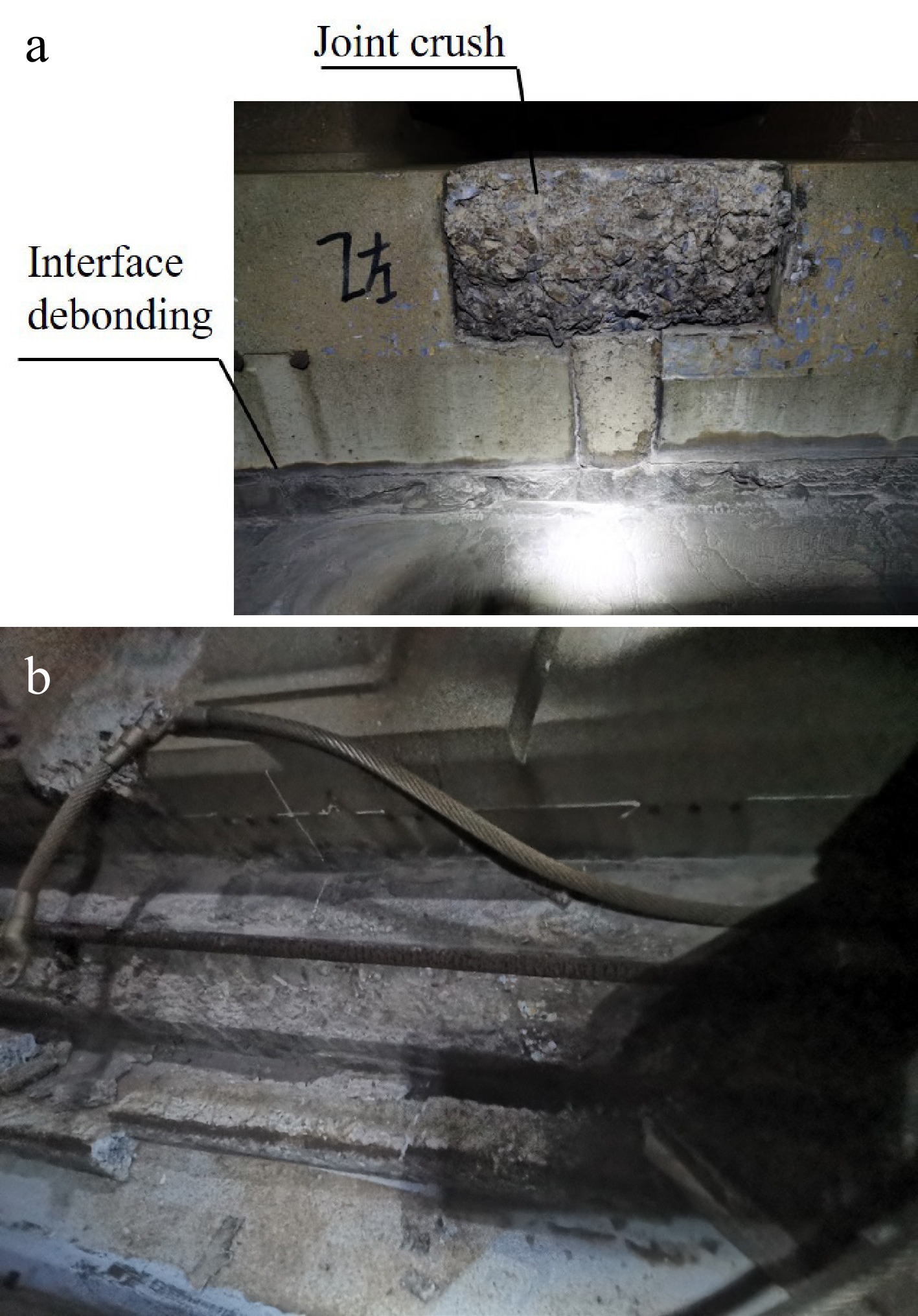
Figure 1.
CRTS II slab track defects.
The damage mechanisms of CRTS II slab tracks have been extensively investigated. Xu et al.[8] employed thermo-mechanical coupling to reveal the spatiotemporal evolution of temperature fields and interface damage under diurnal loading. Through model tests, Xu et al.[9] derived the buckling deformation curve and proposed an analytical equilibrium path. Su et al.[10] characterised the Mode I/II fracture behaviour of the concrete–CA mortar interface, providing a basis for modelling interlayer bond strength[11]. To further examine interface damage evolution, Cui et al.[12] used a cohesive zone model to assess thermal responses, while Dong et al.[13] focused on joint behaviour under temperature fields. Lu et al.[1] studied interlayer damage propagation under train-induced hydraulic pressures, establishing a bilinear cohesive model and a damage-evolution framework. Regarding overall stability, Xu et al.[14] analysed critical instability mechanisms under thermal loads. Additionally, Song et al.[15], Su et al.[16], Li[17], Ma[18,19], and Cui[5] systematically studied interlayer arching and debonding from various perspectives.
For existing damage, engineering practice predominantly employs reactive repair measures, primarily anchoring reinforcement and grouting. Low-viscosity grouting resins and similar repair materials are widely used to bond cracked track interfaces[20,21]. In the context of interlayer debonding repair in CRTS II slab ballastless tracks, Wu et al.[22] introduced epoxy resin and systematically investigated the static and fatigue performance of the concrete slab–epoxy resin interface. Xie et al.[23] examined the diffusion behaviour of repair slurry for interface damage during interlayer repair and identified key factors affecting grouting filling effectiveness. It should be noted, however, that interlayer grouting is a post-damage treatment and cannot effectively prevent the initiation of damage. Anchoring reinforcement of the track slab is also widely adopted in engineering practice. Chen et al.[24] studied the structural response of CRTS II slab ballastless tracks under high-temperature loading and evaluated the applicability of post-installed reinforcement (PIR) anchoring measures. Furthermore, based on their analysis of track slab uplift, Zhong et al.[25] employed anchoring reinforcement as a corrective measure. Although this method can effectively restrain slab uplift, its implementation involves high costs and negatively impacts the long-term service life of the track slab. Reflective thermal insulation coatings[26−28] are employed as a thermal protection measure. Li et al.[29] applied reflective coatings on the surface of the track structure to reduce the risk of track slab expansion and cracking damage.
Recognizing the limitations of traditional repair methods, the research frontier has shifted towards seeking fundamental solutions at the structural system level. This involves altering the longitudinal connection of the track to release temperature-induced stresses, representing a shift from 'passive resistance' to 'proactive adaptation'. Several pioneering studies have proposed concepts such as converting continuous tracks into a 'weak longitudinal connection system'[29], or a 'unitized track system'[30]. The essence of this approach lies in eliminating or significantly reducing the longitudinal restraint between track slabs, thereby mechanically preventing excessive accumulation of temperature stress. This represents a shift in design philosophy from 'passive resistance' to 'proactive adaptation'.
Current research on 'weak connections' has primarily focused on conceptual proposals or macro-level structural modifications, while specific technical pathways to achieve a controllable, reliable, and easily implementable 'weak connection' remain underexplored. In particular, under the premise of maintaining the overall integrity of the track structure, how to precisely regulate the longitudinal connection stiffness through material and structural design—so as to balance stress release and track smoothness—is a technical issue that requires further clarification.
To address this, a 'longitudinal-weak-connection' layout scheme is proposed in this study. Instead of altering the main track structure, this scheme focuses on reducing the elastic modulus of the filling material in the wide and narrow joints, thereby creating a 'flexible segment' at the joints capable of coordinated deformation. The main considerations of this scheme include: (1) Ease of implementation: only the joint material needs to be modified, without changing the main structure; (2) Clear mechanism: the controlled longitudinal stiffness of the joints allows orderly release of temperature-induced stress; (3) System balance: it aims to identify a stiffness range that can effectively mitigate slab uplift while maintaining the overall stiffness and stability of the track system. Through numerical simulations and field testing, this study will analyze the mechanical behavior and implementation feasibility of the scheme, in order to provide a practical solution to the slab uplift problem in CRTS II ballastless tracks.
-
Based on the structural characteristics of CRTS II slab tracks on simply supported beam bridges, a finite element model of CRTS II slab track for the unlocking and relocking process was established. An element activation and deactivation function was used to achieve the replacement of wide and narrow joints, ensuring the model accurately captures the stress state of track slabs during unlocking and relocking operations. The finite element model of the CRTS II slab track unlocking and relocking on the bridge consists of two primary components: the bridge structure system, and the track structure system. According to the Sanwa-Nan principle, to ensure that the forces and deformations of the core research object (the bridge section) fully enter the 'stable state', unaffected by the two ends, in the model, the roadbed sections at both ends of the bridge were extended outward by 100 m. This length (approximately three times the single-span span) is generally considered in structural mechanics analysis to be sufficient to allow the boundary constraint effects at the bridge ends to be fully diffused and attenuated. To mitigate the boundary effects on the structure, a 100 m subgrade transition section (including the post-construction anchoring system) are set up at both ends.
In the bridge system, the simply supported beam is simulated using C3D8R solid elements, while a two-fabric-one-membrane layer is simulated using contact elements with a friction coefficient of 0.3. The interfacial relationship between the track slab and the base slab was simulated using a contact model. This approach was adopted because contact modeling can effectively represent the condition of complete debonding of the CA mortar. Under such contact conditions, the longitudinal displacement of the track structure after unlocking reaches its maximum, thereby allowing for the analysis of the most unfavorable scenario. In the model, the normal behavior was defined as hard contact, while the tangential behavior was characterized by a friction coefficient of 0.3. In the track system, the rail is modeled using B31 beam elements to accurately depict the rail cross-section, while the fasteners are represented by nonlinear spring elements in the X, Y, and Z directions. The track slab, wide and narrow joints, CA mortar layer, and base plate are all simulated using C3D8R solid elements. In the post-construction anchoring system, the friction plate is simulated using contact elements with a friction coefficient of 0.7, and the end spikes and subgrade are both simulated using C3D8R solid elements to represent the actual structure. The mechanical model of the CRTS II slab track is shown in Fig. 2. During the modeling process, the nonlinear behavior of the CRTS II slab track system was fully considered. The WJ-8 type fasteners were adopted, and their longitudinal resistance was characterized using a bilinear resistance model to describe the nonlinear longitudinal behavior. The lateral stiffness of the fasteners was set to 50 kN/mm, and the vertical stiffness was 35 kN/mm. The longitudinal resistance-displacement curve is shown in Fig. 3. The nonlinear material behavior of concrete was not considered in this study. This is because the nonlinear response of concrete structures such as the track slab, base slab, and bridge—specifically, the transition from elastic to plastic deformation—typically occurs only under extremely high external loads. Furthermore, these concrete components in the actual structure are reinforced with steel bars, making it difficult for plastic deformation to develop under ordinary service loads. Therefore, the nonlinear constitutive behavior of concrete was not incorporated into the model. The material structure parameters are set as shown in Table 1.
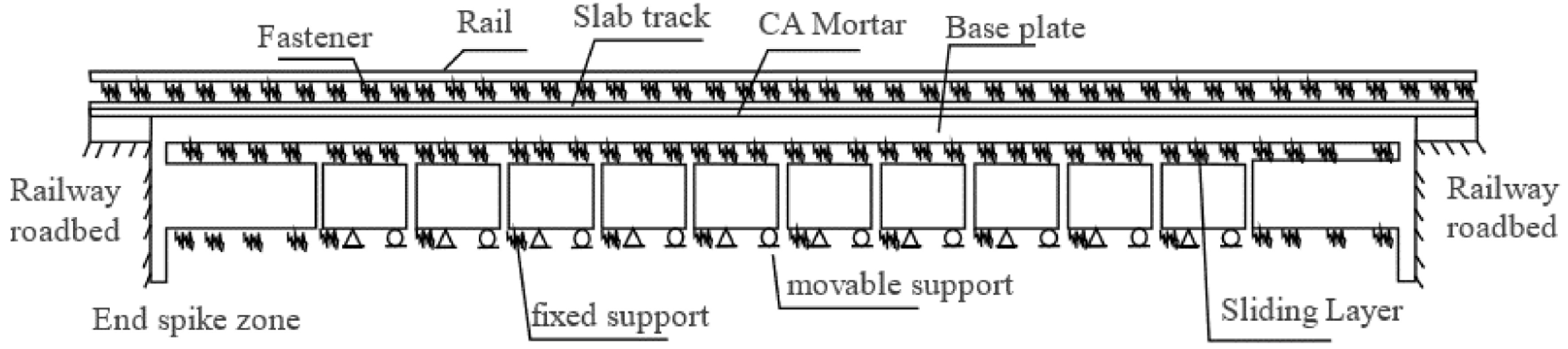
Figure 2.
Mechanical model of the CRTS II slab track system.
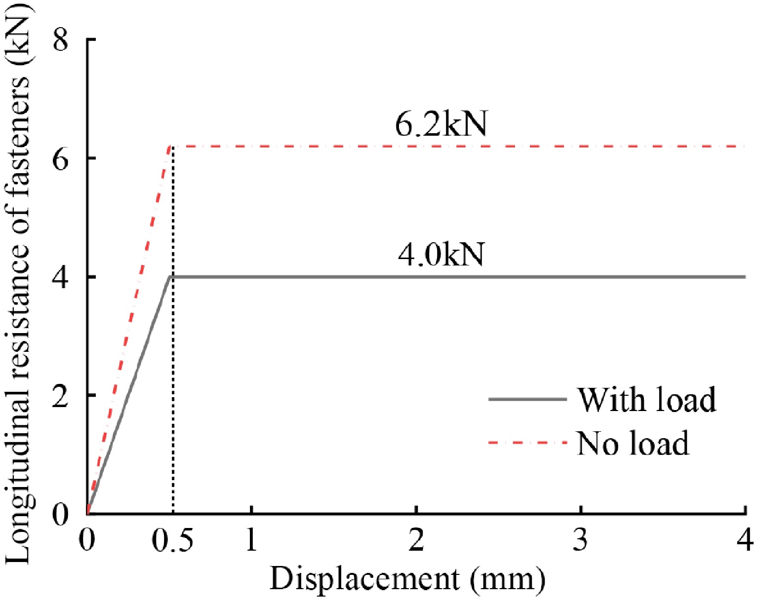
Figure 3.
Low-resistance fastener of WJ-8.
Table 1. Material parameters of the CRTS II slab track system on bridges.
Components Materials Elastic modulus (GPa) Poisson ratio Thermal expansion coefficient (°C−1) Rail Steel 210 0.2 1.18e-5 Slab Concrete 35.5 0.2 1.18e-5 Joint Concrete 35.5 0.2 1.18e-5 CA mortar[31] − 7 0.2 1.18e-5 Concrete base Concrete 32 0.2 1.18e-5 End spikes Concrete 32 0.2 − Abutment Concrete 34.5 0.2 − A/B fillers[31] − 0.12 0.2 − Cement-stabilized crushed stone 0.19 0.2 − Unlocking and relocking scheme design
-
Embedded reinforcement bars are installed near the beam joints on multi-span simply supported bridges. A 32.5 m simply supported beam can accommodate five track slabs. Based on these basic conditions, a '3 + 2' track slab weak longitudinal connection scheme is proposed, as shown in Fig. 4.
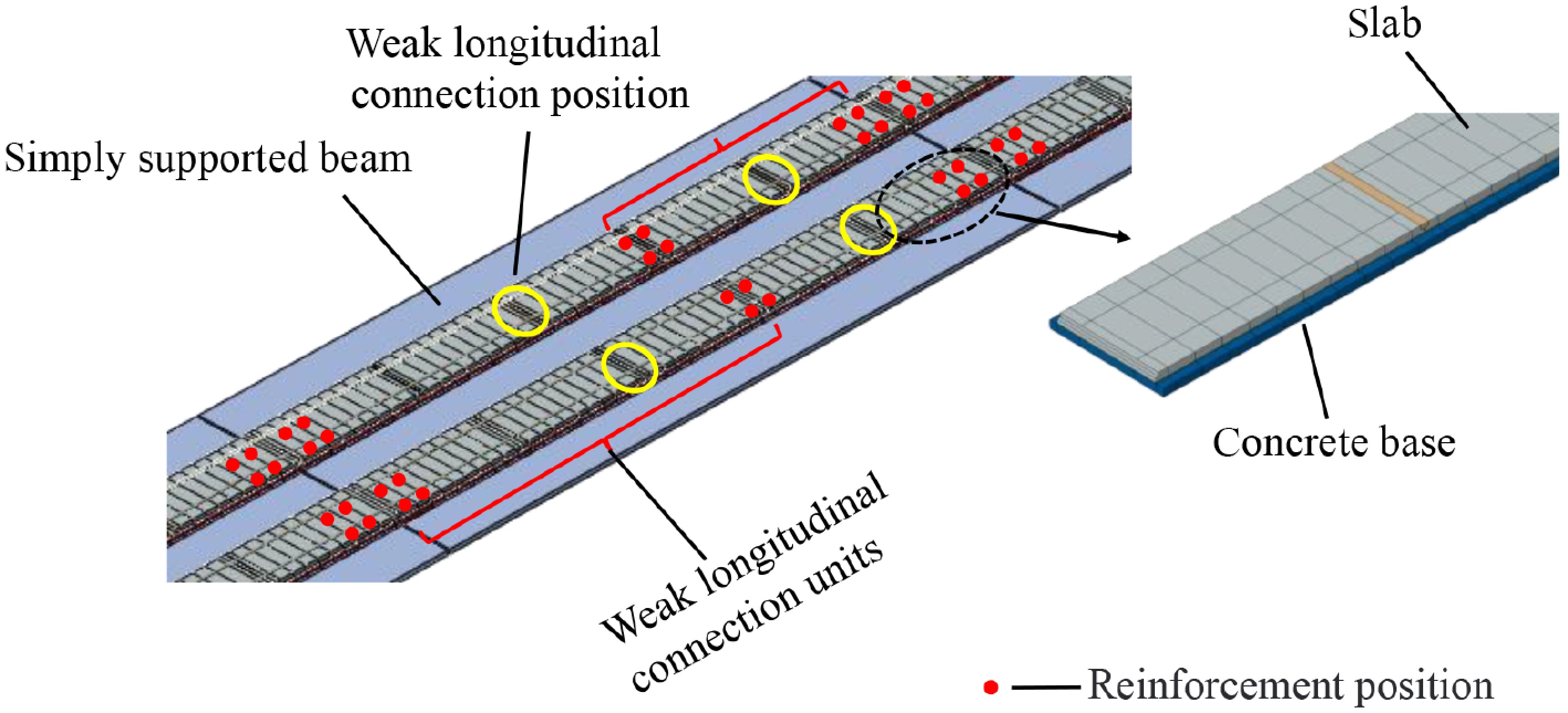
Figure 4.
Weak longitudinal connection scheme.
Assumptions of the unlocking and relocking scheme
-
The track-bridge coupled finite element model includes rails, fasteners, prefabricated slabs, concrete joints, concrete base slab, and the simply supported beam. The stress-deformation behavior of track structures on bridges with unlocked track systems exhibits significant temperature dependence, particularly influenced by differential unlocking temperatures. Furthermore, uncertainties in interlayer bonding conditions under field environments critically affect the mechanical state of layered components following track slab unlocking. Due to the lack of a unified standard for the current weak longitudinal connection scheme, different weak longitudinal connection schemes after unlocking the track slab will lead to significant differences in stress-deformation behavior. The following assumptions are made:
(1) It is postulated that the CRTS II slab track has an initial construction locking temperature of 20 °C, at which the track slab maintains a zero-stress state.
(2) To prevent excessive stress-induced deformation at unlocking positions, symmetrical unlocking operations shall be implemented from both ends of simply-supported beams during track slab unlocking and relocking procedures.
(3) After unlocking, the residual stress field and interlayer bonding status are defined as the initial boundary conditions for the track system during re-locking stabilization procedures.
Model verification
-
Before re-locking, the CRTS II slab track structure is still a longitudinally connected system, thus, literature[32] is selected for comparative analysis to verify the correctness of the model in its longitudinally connected state. The subgrade section on both sides of the reference is 150 m, which is slightly different from that in this paper, while the rest of the structure is the same. Under the braking load of the train, taking the longitudinal force and longitudinal displacement of the rail as indicators, the calculation results are compared with the literature as shown in Fig. 5a, b. Under the heating condition[31], a positive temperature gradient of 90 °C/m was applied to the track slab, while the base plate and the CA mortar layers were uniformly heated by 35 °C, as shown in Fig. 5c, d. The comparative analysis shows that the distribution law of rail force and rail displacement is consistent. Therefore, the finite element model established in this paper is reliable and can be used for subsequent calculations.
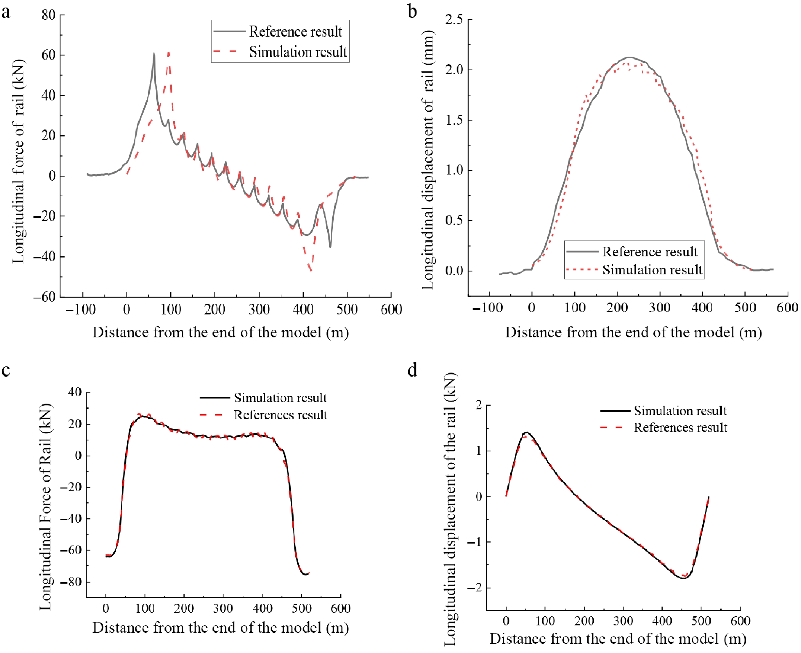
Figure 5.
Model calculation results: (a) additional rail expansion force; (b) rail expansion displacement; (c) results of rail force under high temperature, and (d) results of rail displacement under high temperatures.
-
When unlocking and relocking the CRTS II slab track, three key issues must be prioritized for consideration: Firstly, different bonding conditions can lead to different stress patterns, which in turn affect the overall structural behavior of the track. Secondly, after multiple seasonal cycles, the locking plate temperature of the CRTS II slab track will change. When there is a temperature difference between the unlocking temperature and the locking plate temperature, the stress and strain distribution of the track structure after unlocking will vary. Thirdly, the state of the rail fasteners during construction may also impact the stress and strain distribution of the track structure after unlocking.
Interlayer bonding state
-
In actual sections of CRTS II slab track, where slab uplift damage occurs, on-site investigations have shown that in some areas, there is a significant gap between the track slab and the CA mortar. The bonding effect of the CA mortar has basically disappeared, and it can be regarded as a completely detached state. If there is a bond between layers, its constraining effect will inhibit relative sliding, thereby causing the calculated results to be overly conservative. To analyze the distribution laws under the most unfavorable conditions, the interlayer bonding was modeled as debonding, consistent with field investigation data and simulation requirements. The temperature of unlocking and relocking is 30 °C, without loosening the rail fasteners, and the rail longitudinal force, track slab longitudinal stress, and base plate longitudinal stress are analyzed under different unlocking degrees.
The longitudinal force distribution in the rails after unlocking is illustrated in Fig. 6a. Following the initial step of eliminating wide and narrow joints, a significant reduction of approximately 225 kN in longitudinal force is observed within the unlocked section, corresponding to the wide and narrow joints. Conversely, an increase of 38 kN in longitudinal force is detected in the adjacent unlocked area. During the second phase of midspan unlocking, an analogous pattern of tensile force redistribution emerges, characterized by a progressive increase in tensile force at the target midspan unlocking position, accompanied by a corresponding gradual decrease in tensile forces at the previously unlocked sections on both sides. After the fifth step of unlocking, the distribution of the longitudinal force of the rails presents the characteristic that the longitudinal force of the rails on the bridge is less than that before unlocking, while the longitudinal force of the rails on the subgrade is greater than that before unlocking. The longitudinal stress distribution during the track slab unlocking process is illustrated in Fig. 6b. Before unlocking, the longitudinal stress of the track slab on the bridge is about 4.5 MPa, and the overall state is compressive.
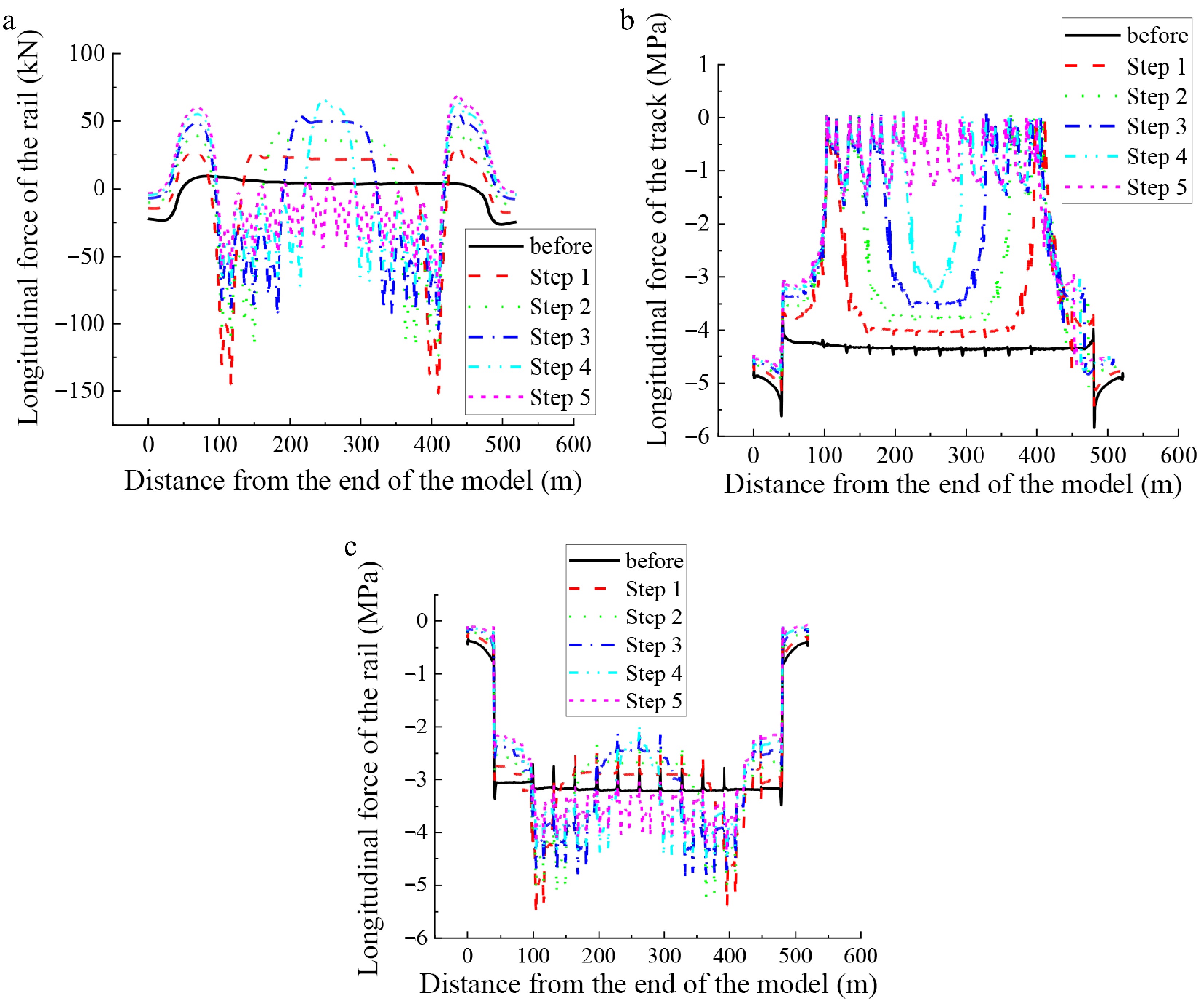
Figure 6.
Longitudinal force situation of the track structure during the unlocking process. (a) Unlocking process rail longitudinal force; (b) unlocking process track slab longitudinal stress; (c) unlocking process base slab longitudinal stress.
Following the initial removal of wide and narrow joints, the longitudinal stress in the track slab demonstrates significant changes: the stress at the former joint locations approaches 0 MPa, while a reduction to approximately 4 MPa is observed at the mid-span bridge section where unlocking has been implemented. After the second step of removing the wide and narrow joints, the longitudinal stress of the track slab in the middle, unlocked section is further reduced. Due to the effect of the interlayer anchor steel, the longitudinal stress of the track slab cannot be completely released, resulting in a stress peak. The magnitude of the stress peak is approximately 1.5 MPa. After the fifth step of unlocking is completed, the overall longitudinal stress of the track slab on the bridge is close to 0 MPa. Due to the effect of the interlayer anchor steel, the stress release is not complete, resulting in a small range of stress peaks.
The distribution of longitudinal stress in the base plate during unlocking is shown in Fig. 6c. Before unlocking, the longitudinal stress in the base plate is approximately 3.2 MPa. After the first step of removing the wide and narrow joints, the relative displacement between the structures increases, and the longitudinal stress in the base plate increases by approximately 2.6 MPa. The longitudinal stress in the base plate in the middle section that is not unlocked decreases slightly. After the fifth step of unlocking is completed, the stress in the base plate suddenly increases. The longitudinal stress of the base plate after final unlocking is approximately 0.3 MPa higher than before unlocking.
Influence of fastener conditions
-
The behavior of rail fasteners during track slab unlocking and relocking operations warrants particular attention. All rail fasteners are loosened to unlock the track slab, and the longitudinal force of the rail, the longitudinal stress of the track slab, and the longitudinal stress on the base plate are compared and analysed, as shown in Fig. 7.
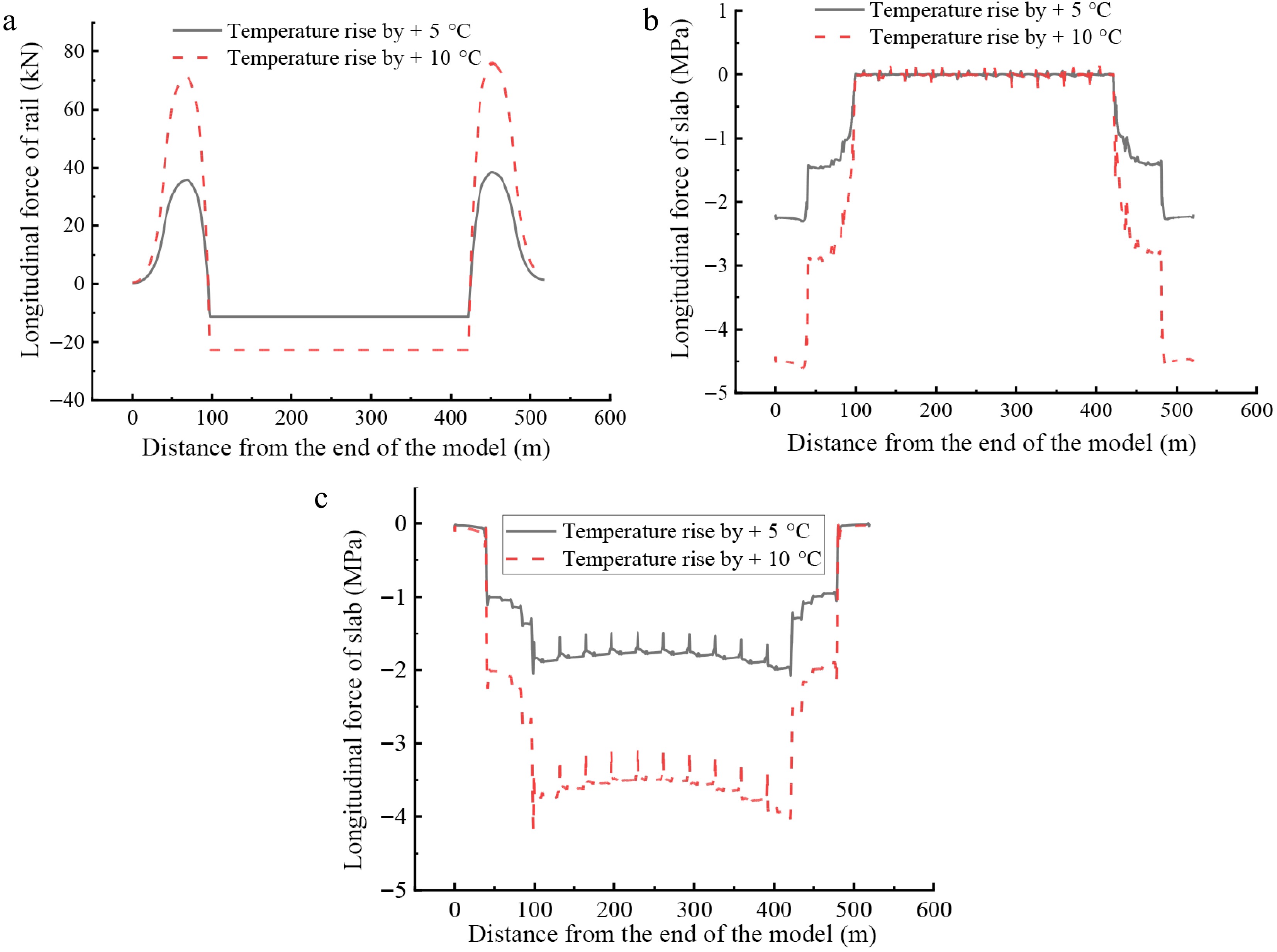
Figure 7.
Longitudinal force of track slab after unlocking. (a) Longitudinal force of rail; (b) longitudinal force of track slab after unlocking; (c) longitudinal force of base slab.
Overall, loosening the rail fasteners will lead to an increase in the overall stress deformation of the track structure. When the temperature drops by 5/10 °C or rises by 5/10 °C, the maximum longitudinal force of the rail occurs at the side span, with values of 38.33, 76.19, 38.9, and 76.61 kN. The longitudinal stress of the track slab basically reaches zero stress after unlocking. Due to the lack of constraints from the rail fasteners, the interaction between the beam and rail decreases, the constraint of the track slab weakens, and the longitudinal displacement of the track slab increases, which is larger than that without loosening the rail fasteners. When the temperature rises by 10 °C, it can reach 4.5 mm. The stress deformation of the base plate is larger compared to the case when the fasteners are not loosened. The increase in stress on the base plate is relatively small. When the temperature drops by 10/5 °C, or rises by 5/10 °C, the stress increases by 0.06, 0.03, 0.03, and 0.05 MPa, respectively. The longitudinal displacement of the base plate increases by 0.44, 0.25, 0.41, and 0.46 mm, respectively. The force-deformation characteristics of the track slab structure under fastener release conditions are systematically presented in Table 2.
Table 2. Force-deformation characteristics of the track slab under released and fixed fastener conditions at various unlocking temperatures.
Unlocking temperature of track slab Temperature drop 10 °C Temperature drop 5 °C Temperature rise 5 °C Temperature rise 10 °C N Y N Y N Y N Y Maximum longitudinal force of rail (kN) 108.57 76.61 54.73 38.87 47.58 38.35 105.92 76.19 Maximum longitudinal displacement of rail (mm) 1.89 2.00 0.94 1.02 0.79 0.92 1.85 2.00 Maximum longitudinal force of track slab (MPa) 0.36 0.05 0.14 0.02 −0.20 −0.22 −0.40 −0.45 Maximum longitudinal displacement of track slab (mm) 3.84 4.49 1.82 2.27 1.78 2.26 3.74 4.50 Maximum longitudinal force of base plate (MPa) 3.54 3.49 1.77 1.75 −1.77 −1.75 −3.55 −3.5 Maximum longitudinal displacement of base plate (mm) 1.50 1.94 0.68 0.93 0.71 1.12 1.54 2.00 N represents unlocking the rail fastener, Y represents not unlocking the rail fastener. Different relocking temperature conditions
-
After the track slabs on the bridge are unlocked, high-early-strength concrete is used to complete the pouring of the wide and narrow joints in a short period of time. Existing research suggests that the temperature of the track slabs on the bridge is 22−23 °C higher than the air temperature in warm regions. The temperature of the track slabs is not significantly different from the local minimum temperature. Considering the impact of extreme climate conditions, the highest temperature in warm regions is taken as 45 °C, and the lowest temperature is taken as −20 °C. Therefore, the temperature range of the track slabs is −20 to 70 °C. When the unlocking temperature is 30 °C, the maximum temperature rise after locking can reach 40 °C. Using the element activation and deactivation of the finite element software, the replacement of the wide and narrow joints is realized, and the track structure is heated by 40 °C to analyze the stress-strain behavior of the track structure.
The elastic moduli of the wide and narrow joints were set at 35,500, 10,000, 8,000, 4,000, and 1,000 MPa respectively. The longitudinal stress structure of the track slab under a temperature increase of 35 °C was calculated as shown in Fig. 8. It is clearly observable that different elastic moduli have different effects on the longitudinal stress of the track slab. When the elastic modulus is 35,500 or 10,000 MPa, the longitudinal stress of the track slab decreases slightly. When it is less than 10,000 MPa, the longitudinal stress of the track slab decreases significantly. The current 10,000 MPa adopted is a representative value based on engineering experience, aiming to simulate the mechanical state of the joint material after weakening, and it does not represent the specific value of the elastic modulus. However, it can prove that reducing the elastic modulus can indeed reduce the longitudinal stress inside the track slab.
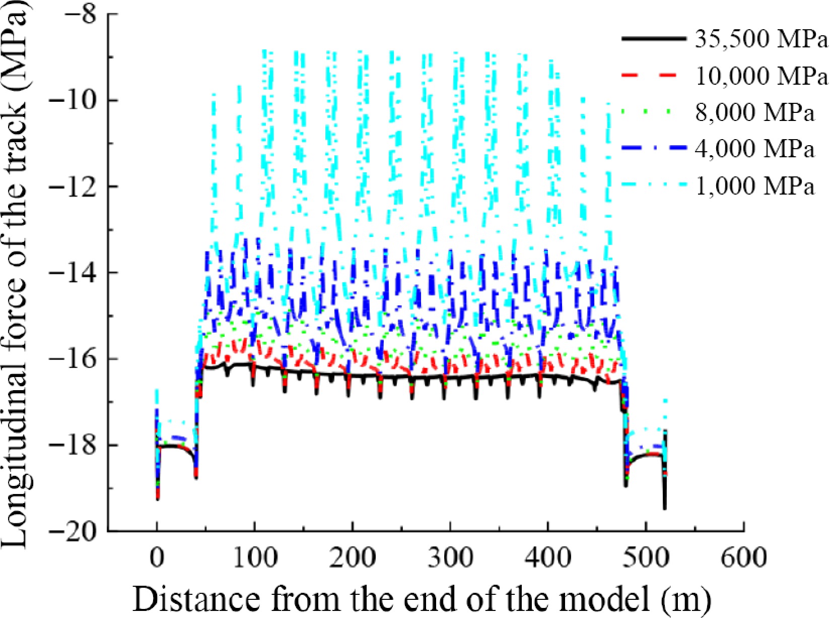
Figure 8.
Longitudinal force of track slab under different elasticity modulus.
Taking the temperature rise condition as an example, the modulus of the original concrete is temporarily taken as 1/3, which is approximately equal to 10,000 MPa. The stress-strain behavior of the CRTS II type slab track after relocking is analyzed. The positive and negative values of the longitudinal force of the track structure represent tension and compression, respectively. The law of the longitudinal force of the track structure on the bridge is closely related to the relocking slab temperature, as shown in Fig. 9. When the relocking slab temperature is higher than the initial construction locking temperature of the track slab (temperature rise to 40 °C, temperature rise to 45 °C), the rail is compressed upon relocking. When it is lower than the initial construction locking slab temperature (temperature rise to 55 °C, temperature rise to 60 °C), the rail is tensile. The brittle fracture of the rail under tension directly threatens the safety of the rail. The damage caused by the compression of the rails is usually promptly repaired as part of the routine maintenance of the rails. Therefore, the relocking slab temperature should be higher than the initial locking slab temperature of the track slab. The rail under pressure is beneficial in the later period. The smaller the temperature of the track slab, the greater the temperature rise after re-locking, and the greater the longitudinal stress of the track slab. When the temperature of the slab rises to 60 °C, the maximum longitudinal stress of the track slab can reach 33.2 MPa, which is close to the compressive strength of C55 concrete (35.5 MPa), and is within the safe range. The longitudinal stress of the base plate is related to the temperature rise. The smaller the temperature of the base plate, the greater the temperature rise after re-locking, and the greater the longitudinal stress of the base plate. When the temperature rises to 60 °C, the maximum longitudinal compressive stress of the base plate can reach 23.9 MPa, which exceeds the compressive strength of C30 concrete (22.5 MPa), and it will cause the concrete to be crushed. Therefore, it is necessary to determine the re-locking slab temperature range reasonably to ensure that the stress of the slab is within a reasonable range.
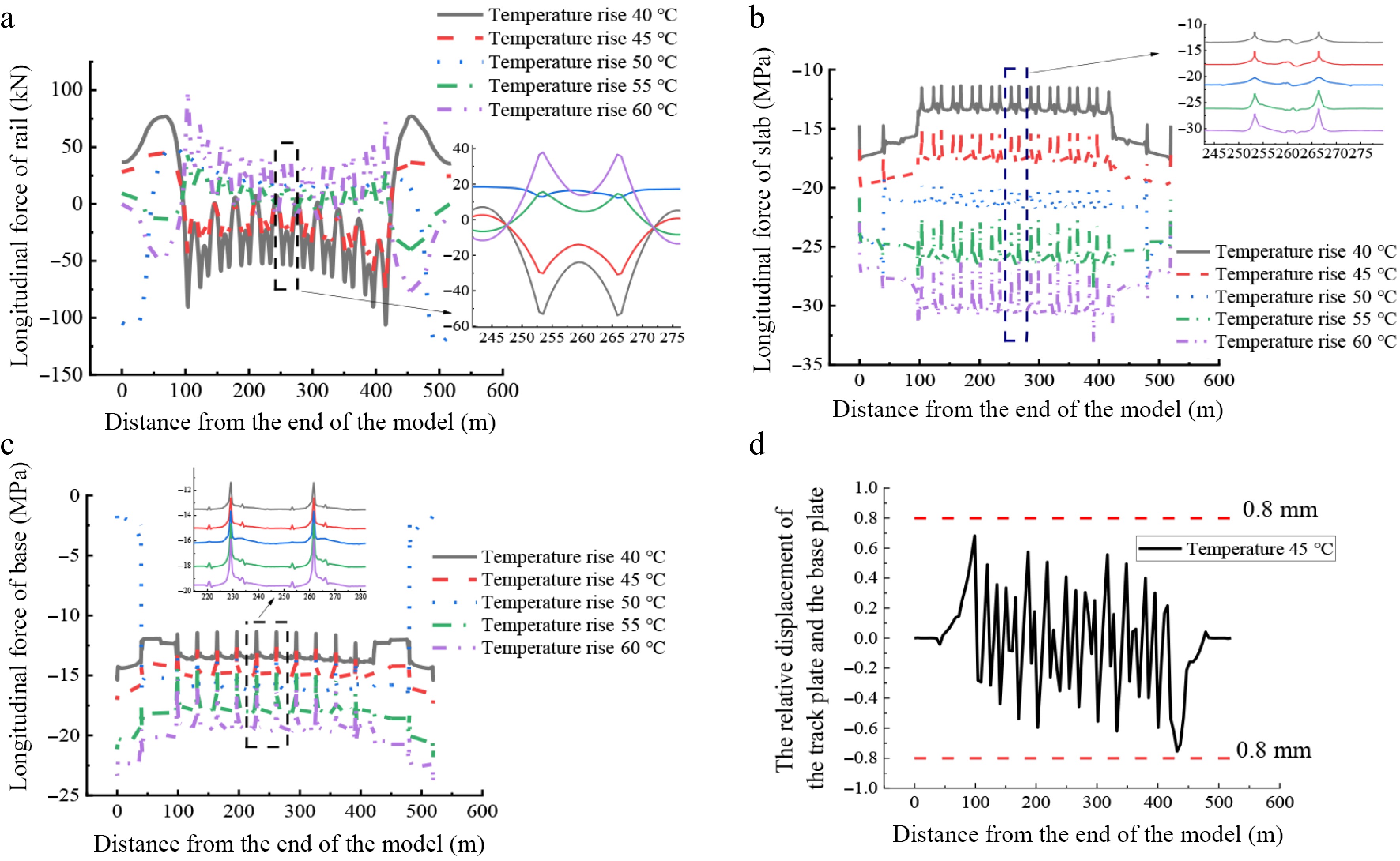
Figure 9.
Force-deformation of the track structure under different unlocking and relocking. (a) Longitudinal force of the rail; (b) longitudinal stress of the track slab; (c) the longitudinal force of the base plate, and (d) relative displacement between slab and the plate.
The longitudinal displacement between the track slab and the base plate should focus on the interlayer relative displacement. When the temperature rises to 45 °C, the maximum relative displacement between the interlayer after re-locking is 0.75 mm, and the relative displacement is less than 1 mm. Under these conditions, the track structure is stable and safe. The relative displacement between layers under other working conditions is shown in Table 3.
Table 3. Force conditions of track structure under different unlocking and relocking temperatures.
Temperature rise (°C) Maximum longitudinal
force of rail (kN)Rail deformation
value (mm)Maximum longitudinal
force of slab (MPa)Maximum longitudinal
force of base (MPa)Maximum relative displacement
of base and track (mm)Temperature rise to 40 °C −106.2 0.87 −17.6 −15.4 1.34 Temperature rise to 45 °C −76.3 0.83 −20.0 −17.5 0.75 Temperature rise to 50 °C −122.9 2.58 −28.5 −17.1 0.18 Temperature rise to 55 °C 48.7 0.96 −28.6 −21.8 0.56 Temperature rise to 60 °C 99.7 1.10 −33.2 −23.9 1.25 Temperature drop to 50 °C −94.8 0.82 26.9 20.0 1.12 Temperature drop to 45 °C −48.2 0.66 22.5 17.9 0.56 Temperature drop to 40 °C 88.3 2.10 21.1 13.2 0.16 Temperature drop to 35 °C 61.3 0.79 15.7 13.6 0.77 Temperature drop to 30 °C 104.8 0.92 15.5 13.4 1.62 Temperature drop to 30 °C 104.8 0.92 15.5 13.4 1.62 The rail deformation value and the maximum relative displacement are absolute values; the rail deformation value refers to the displacement before and after re-locking; the positive values of the longitudinal force of the rails, the maximum stresses of the track slab and the base plate represent tension, while negative values represent compression. After relocking, the slab and the base plate is in a compressed state. It can be seen from Table 3 that the compressive strength of the slab and base plate meets the Chinese specification requirements (TB10002.3-2005, 2005) when the relocking temperature ranges from 20 to 25 °C.
-
The Riks method is commonly used in structural nonlinear analysis. Its advantages include computational stability and efficiency, enabling the complete tracking of nonlinear buckling behavior and its paths. Figure 10 shows an iterative solution path based on the arc-length method. Assuming that the i-1 load step converges at (xi−1, λi−1), the tangent line to the curve at this point is AB1. It is necessary to perform j iterations along the arc B1B2Bn. The convergence point of the i load step is (xi, λi). The load factor step size is
$ \Delta \lambda _{i}^{j} $ $ \Delta \lambda $ $ {\left(x_{i}^{j}-{x}_{i-1}\right)}^{2}+{\left(\lambda _{i}^{j}-{\lambda }_{i-1}\right)}^{2}=l_{i}^{2} $ $ {l}_{i}={l}_{i-1}\sqrt{\dfrac{{n}_{d}}{{n}_{i-1}}} $ 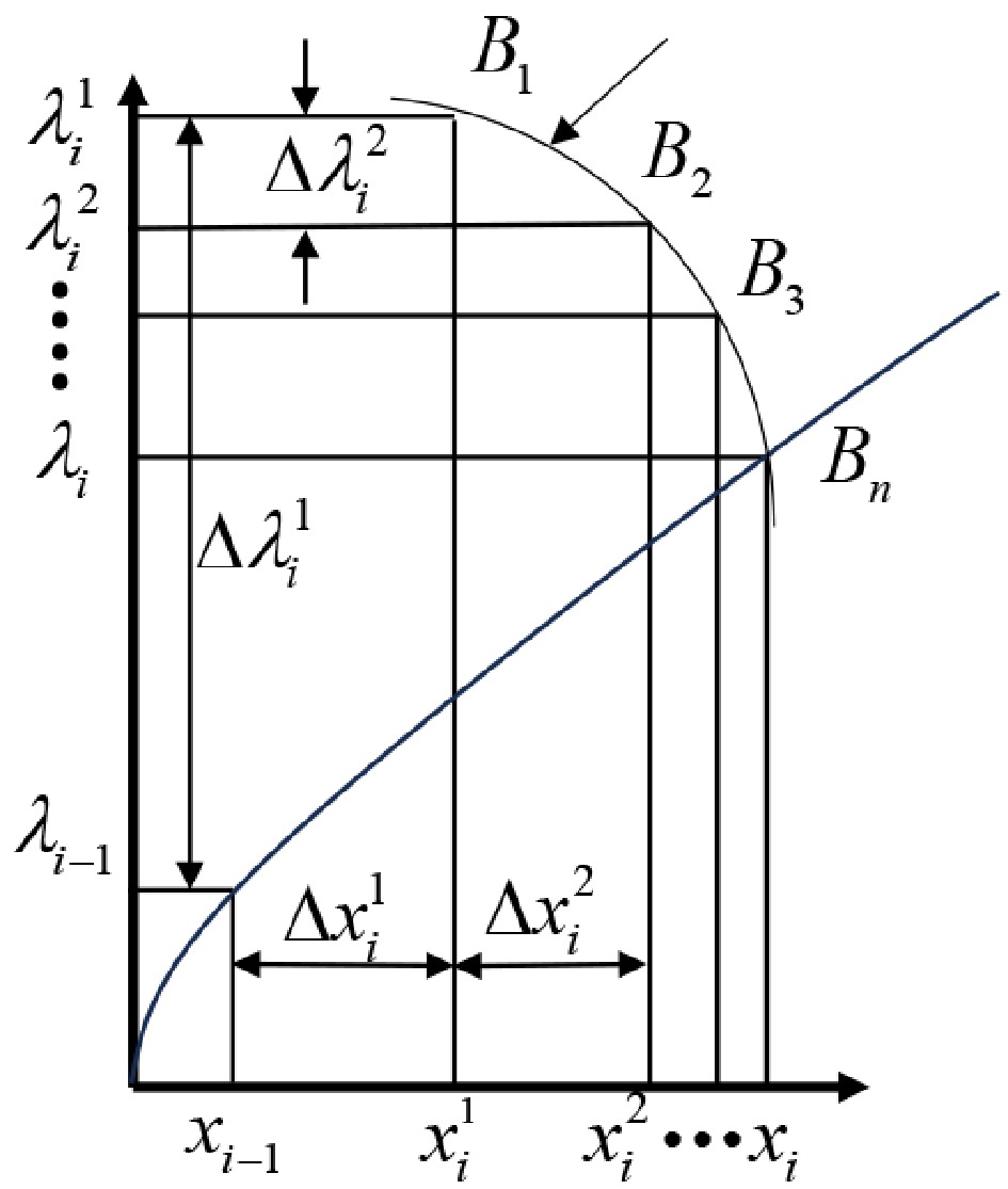
Figure 10.
Risk method iteration curve.
When j = 1, based on the configuration at the end of convergence of the previous load step i-1, the slope of the dashed parallel line in the tangent stiffness of the i load step convergence calculation is obtained, which in turn leads to the tangent displacement, namely:
$ {K}_{i}{x}_{i}={F}_{i} $ (1) $ l_{i}^{2}={\left(\Delta \lambda _{i}^{2}\right)}^{2}+{\left(\Delta _{i}^{1}\right)}^{2}={\left(\Delta \lambda _{i}^{1}\right)}^{2}+{\left(\Delta \lambda _{i}^{1}{x}_{i}\right)}^{2} $ (2) $ \left| \Delta \lambda _{i}^{1}\right| =\dfrac{{l}_{i}}{\sqrt{1+x_{i}^{T}{x}_{i}}} _{ } $ (3) After obtaining
$ \Delta \lambda _{i}^{1} $ $ \Delta \lambda _{i}^{1}\left(x_{i}^{T}{x}_{i-1}+\Delta \lambda _{i-1}^{1}\right) \gt 0 $ (4) When j = 2, solve for
$ \Delta \lambda _{i}^{1} $ $ \left(x_{i}^{j}-{x}_{i-1},\lambda _{i}^{j}-{\lambda }_{i-1}\right)\left(\Delta x_{i}^{j},\Delta \lambda _{i}^{j}\right)=0 $ (5) To ensure a unique solution for the above equation, we supplement it with the following relationship:
$ {K}_{i}\Delta x_{i}^{j}=\Delta x_{i}^{j}{F}_{i}-R_{i}^{j-1} $ (6) $ R_{i}^{j-1}=F_{\mathrm{int}i}^{j-1}-F_{exti}^{j-1},F_{exti}^{j-1}=\lambda _{i}^{j-1}{F}_{i} $ (7) where, Fint is the internal load at the node, Fext is the external load at the node, and R is the residual.
Since the applied temperature is treated as an unknown quantity in the Riks algorithm, the buckling process of the track slab is characterized by a series of equilibrium points. When buckling occurs, a turning point appears in the 'load proportionality factor-displacement curve'. Therefore, the time of the turning point marks the occurrence of structural buckling, and the temperature corresponding to this turning point is the critical buckling temperature of the track slab.
Stability analysis of track slabs after weak longitudinal connection when bridge creep uplifts
-
The stability analysis of ballastless track with weak longitudinal connection is directly related to the elastic modulus of the joint filling material. To understand the stability variation pattern of ballastless track after weak longitudinal connection, the elastic modulus of the filling material was taken as 100, 5,000, 10,000, 15,000, 20,000, 25,000, 30,000, and 35,500 MPa. The critical temperature rise values of the track slab under different elastic moduli was calculated when the weak longitudinal connection scheme was three slabs, and the simply supported beam experienced sinusoidal creep upward, arching with an upward arching amount of 30 mm. The calculation results are shown in Fig. 11a. When the elastic modulus of the filling material is equal to 10,000 MPa, the critical temperature for vertical instability of the track slab is 127 °C, which is much higher than the temperature rise corresponding to the compressive failure of concrete. This indicates that the compressive failure of concrete will occur before the vertical instability of the track slab, and the track slab will not experience vertical instability.
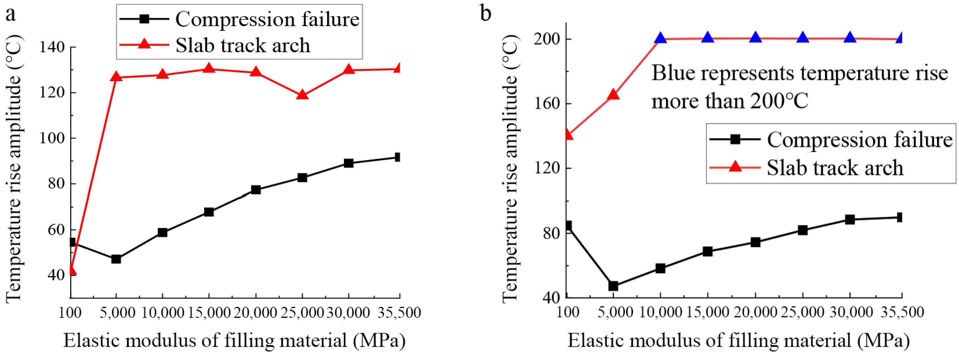
Figure 11.
Critical instability temperature of track slab. (a) Bridge upward deflection; (b) bridge settlement.
Stability analysis of track slab after a weak longitudinal connection due to bridge pier and abutment settlement
-
When the bridge pier and abutment settle, a downward kink will occur at the settlement location, and an upward kink will occur at the adjacent simply supported beam. The upward kink is more detrimental to the vertical stability of the track structure. Therefore, the upward kink is taken as the initial unevenness to analyze the stability of the track structure after a weak longitudinal connection. The settlement value is taken as 50 mm. As shown in Fig. 11b, the critical buckling temperature of the track slab is 140 and 165 °C when the elastic modulus of the inter-segment filling material is 100, and 5,000 MPa, respectively. When the elastic modulus of the material is 10,000 MPa, the critical buckling temperature of the track slab exceeds 200 °C, which does not exist in actual working conditions. This indicates that concrete crushing will occur before the vertical instability of the track slab, and the track slab will not experience vertical instability.
-
To observe the influence of unlocking and relocking on the interlayer state of the joint, the change in the deformation of the plate end after unlocking, and the influence of the on-site relocking construction process on the longitudinal deformation of the ballastless track, a field replacement test of wide and narrow joints was conducted on a ballastless track section of a certain high-speed railway.
Test method
-
The construction site was located on a simply supported beam, and fasteners were not released. First, an electric jackhammer was used to remove the joints and clean out concrete rubble and dust. Second, the tension clamp was tightened, and holes were drilled on both sides of the joints to erect the formwork. The early-strength concrete is then poured. Finally, the concrete rubble and dust is cleaned, and the formwork is removed. The construction flow is shown in Fig. 12.
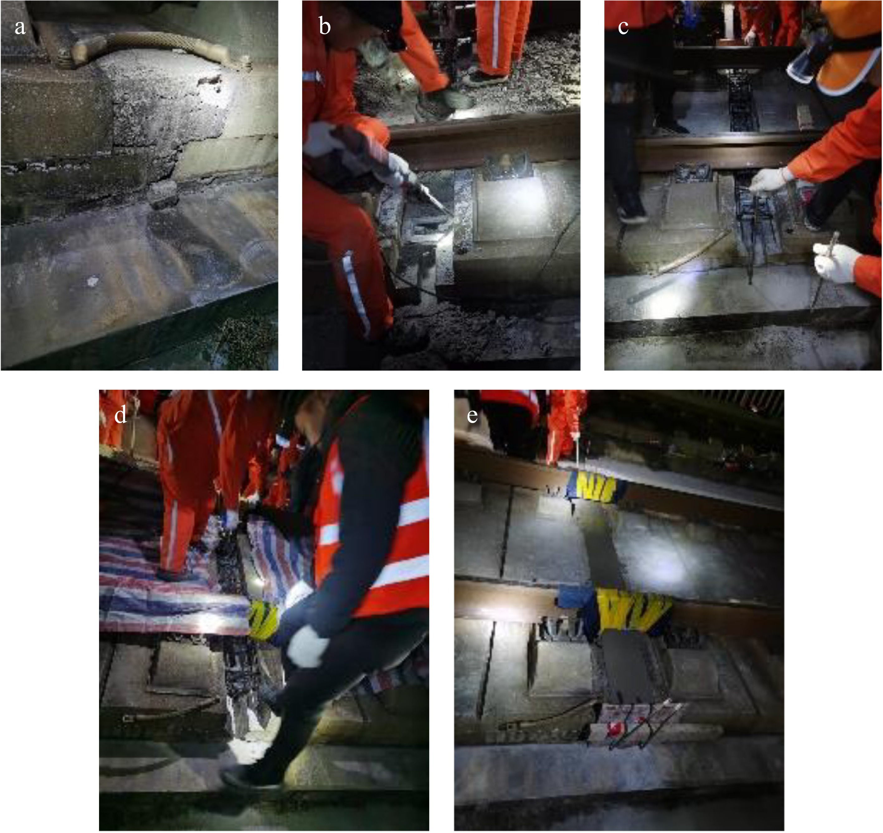
Figure 12.
Track slab unlocking and relocking construction process. (a) Preparatory work; (b) concrete removal; (d) protective measures; (e) concrete backfilling.
Experimental results
-
The initial locking temperature of the track slab in the pre-reinforced section is 20 °C. The experiment was conducted during the track work window. There are nine joints that need to be constructed at the track work window, numbered 1# to 9#. Adhesive measuring tape was applied on both sides of the joints parallel to the line direction, marked A, B, C, and a reference point. The relative distance between the reference points is measured before pouring. To eliminate the error caused by the width of the marked line, one side of the marking line is uniformly selected for reading to ensure the accuracy of the test. When the early strength concrete is poured and stabilized, the reference point is measured again after removing the formwork, as shown in Fig. 13. The measurement results are used as the relative distance of the joints after pouring.
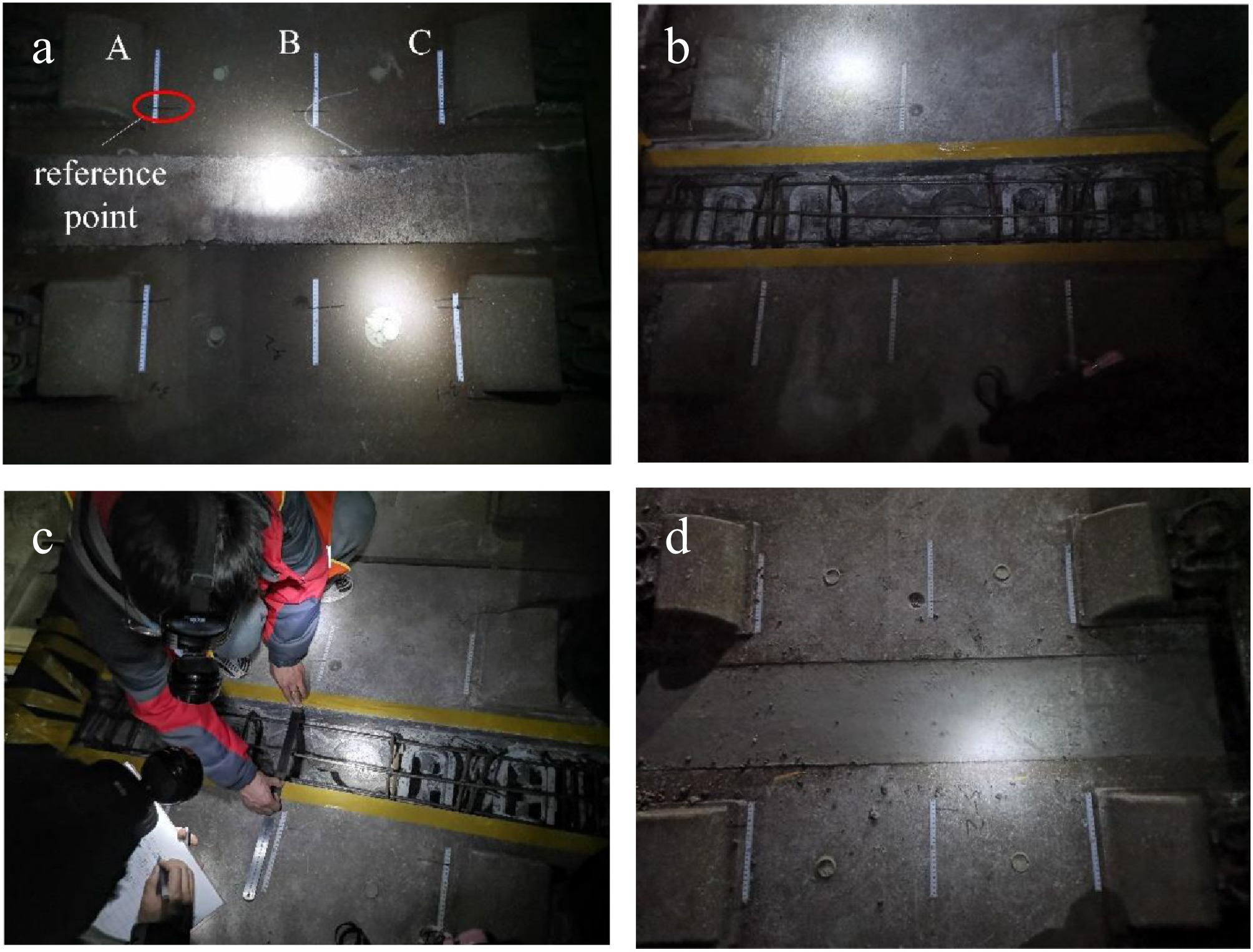
Figure 13.
Relative displacement measurement process. (a) Attaching a scale; (b) measuring distance; (c) measuring distance again; (d) measuring finished.
The relative displacement changes of the slab at both ends of the wide and narrow joints before and after the concrete pouring are shown in Table 4. During the construction phase of the second maintenance window, partial detachment of attached measurement scales occurred due to on-site worker activities, resulting in the availability of measurement data solely from positions A at the 7#–9# wide and narrow joints, as shown in Table 5.
Table 4. Measurement data for joints 1#–6#.
Before pouring
the jointAfter pouring
the jointRelative displacement
changeTime 1:39 2:32 Air temperature (°C) 19.8 19.7 Plate temperature (°C) 19.5 19.4 1-A (cm) 47.90 47.90 0.00 1-B (cm) 49.95 49.95 0.00 1-C (cm) 48.66 48.66 0.00 2-A (cm) 45.70 45.71 0.01 2-B (cm) 44.00 43.99 0.01 2-C (cm) 46.50 46.50 0.00 3-A (cm) 48.10 48.11 0.01 3-B (cm) 47.65 − − 3-C (cm) 49.00 49.01 0.01 4-A (cm) 47.61 47.61 0.00 4-B (cm) − − − 4-C (cm) 46.15 46.15 0.00 5-A (cm) 46.53 46.53 0.00 5-B (cm) 48.50 48.50 0.00 5-C (cm) 47.63 47.62 0.01 6-A (cm) 46.36 46.36 0.00 6-B (cm) − 45.2 − 6-C (cm) − 45.9 − During the process of removing the wide and narrow seams, some of the attached rulers were damaged. The measurement data was not obtained after unlocking and is marked as –. Table 5. Measurement data for 7#−9# joints.
Different conditions Before pouring
the jointAfter pouring
the jointRelative
displacement
changeTime 3:00 3:45 Air temperature (°C) 16.7 16.9 Plate temperature (°C) 17.2 17.8 7-A (cm) 47.90 48 0.00 8-A (cm) 49.95 49.95 0.00 9-A (cm) 48.66 48.66 0.00 The longitudinal displacement of the track slab showed negligible change, with the maximum change in longitudinal displacement of the track slab within 0.1 mm. The temperature change of the track slab is very small and can be considered constant during the time interval between unlocking and pouring the wide and narrow joints on site. Field tests show that to ensure the safety of the track slab during construction, it is recommended to anchor the track slab on both sides of the wide and narrow joints, which will prevent significant longitudinal displacement of the track slab.
-
This paper analyzes the mechanical performance of ballastless track with a weak longitudinal connection scheme from the perspectives of track structure strength, stiffness, and stability. The main conclusions are as follows:
(1) The optimal temperature for unlocking and relocking is within ± 5 °C of the initial locking temperature. Within this range, the wide and narrow joints can be released directly.
(2) During construction involving a weak longitudinal connection, loosening the rail fasteners increases the stress and deformation of the track structure. It is recommended that the rail fasteners are not loosened during the track slab unlocking process.
(3) When unlocking and relocking temperatures are maintained between 20 and 25 °C, both the track slab and base plate possess sufficient compressive strength to meet national safety standards under high-temperature conditions. This ensures that structural damage will not occur.
(4) Even when bridges exhibit upward camber or pier settlement, the critical vertical instability temperature for the track with weak longitudinal connection exceeds 200 °C. Since this temperature is far beyond practical conditions, compressive failure of the concrete will occur before vertical instability. Therefore, the track slab will not experience vertical instability under high-temperature conditions.
(5) Field tests demonstrate that longitudinal displacement of the track slab during unlocking and relocking is negligible, with variations limited to 0.1 mm. Moreover, the construction process preserves interlayer integrity, with no observed separation.
-
The authors confirm contributions to the paper as follows: studyconception and design: Cai J, Wang J; data collection: Chen J, Li Y, Zhao C, Zhang J; analysis and interpretation of results: Li Y, Shi X, Chen J; draftmanuscript preparation: Li Y, Shi X, Chen J. All authors reviewed theresults and approved the final version of the manuscript.
-
The datasets generated during and analyzed during the current study are available from the corresponding author upon reasonable request.
-
The National Natural Science Foundation of China (Nos 52378454, 52508510, and 52408486), the Natural Science Foundation of Hebei Province, China (Nos E2024210065, E2022210086). The Research Project of National Railway Administration of China (No. KF2024-052), and the Science and Technology Development Project of China Railway Design Group Co., Ltd (No. 2023A0203603).
-
The authors declare that they have no conflict of interest.
- Copyright: © 2026 by the author(s). Published by Maximum Academic Press, Fayetteville, GA. This article is an open access article distributed under Creative Commons Attribution License (CC BY 4.0), visit https://creativecommons.org/licenses/by/4.0/.
-
About this article
Cite this article
Cai J, Chen J, Shi X, Wang J, Li Y, et al. 2026. Study on mechanical properties of CRTS II slab track construction process based on weak longitudinal connection scheme. Digital Transportation and Safety 5(1): 53−64 doi: 10.48130/dts-0026-0005 

Study on mechanical properties of CRTS II slab track construction process based on weak longitudinal connection scheme
- Received: 10 November 2025
- Revised: 29 January 2026
- Accepted: 04 March 2026
- Published online: 31 March 2026
Abstract: In summer, unpredictable arching of the track slab frequently occurs in the CRTS II slab track system. This paper proposes a 'weak longitudinal connection' method to release the internal temperature stress. A finite element model of the track structure, with unlocking and relocking connections on bridges was established. The mechanical properties of the track slab with weak longitudinal connections are analyzed in terms of strength, stiffness, and stability. Field tests were conducted, and the results indicate that when the temperature difference between locking and unlocking is within 5 °C, the joints can be directly released. It is recommended to unlock the track slabs without loosening the rail fasteners. When the unlocking and relocking plate temperatures are 20 and 25 °C, respectively, the compressive strength of the track slab and base plate meets safety requirements. After a weak longitudinal connection, the track will not experience vertical instability under high temperature conditions. The compressive failure of the track structure occurs earlier than the vertical instability failure of the track slab. Field construction tests show that the longitudinal displacement of the track slab during unlocking and relocking is almost unchanged, with a difference of about 0.1 mm. There will be no interlayer gaps between the track slabs due to construction.