


-
Natural disasters affecting large, densely populated areas are a frequent scenario worldwide. Earthquakes are among the natural events that may cause extensive damage to buildings, affecting both structural as well as non-structural elements. Similarly, industrial explosions, flood debris and mud, for instance, may also cause damage to buildings and industrial facilities.
The extent of these damages has a direct impact on the building's occupancy, in the aftermath of an earthquake, as well as the costs of reconstruction or strengthening. Therefore, its accurate assessment is of crucial importance. The post-seismic evaluation of structures is intended to decide whether a structure (building) can remain safely in use, could be strengthened, or should be evacuated and demolished. This evaluation process must be conducted in the short term, in the early hours and days after the occurrence of an earthquake. Therefore, a reliable but readily global damage measure is necessary to undertake adequate actions.
Depending on the level of damage, each building is, in the case of a post-quake evaluation campaign, considered as being in on of the following categories: 'Green tag: remain in service and no evacuation is needed'; 'Orange tag: evacuate until further detailed evaluation is performed'; 'Red tag: evacuate and demolish'[1−8]. It is worth noting that most of the current methods for quick visual inspection have an empirical basis[1−6]. For instance, five categories of damage are currently used in Algeria. Although they are derived from engineering expertise and know-how, there is no rigorous mechanical modeling behind the empirical classification. Therefore, the method has some limitations and needs improvements. It does not make a difference between a building with a column having a given damage at the bottom of the building with another column having the same damage at the top of the building. Obviously, damage at the bottom will greatly influence the whole building integrity whereas damage at the top will influence only the upper story. The strengthening and repair will then be different for the two cases. By extension, damage at a lower story will have a larger influence than the same damage at the upper story. In addition, a column at the edge of the building will have a different influence than a column in a central position. Therefore, there is a need to improve the existing evaluation forms for quick visual inspection by providing scientific support for the classifications, able to relate the damage of an individual element (beam and column for framed structures) to the damage of the whole story related afterwards to the damage of the story (its location is of crucial importance), and the global damage of the whole structure.
Thus, the damage evaluation campaign has a crucial importance as it impacts the urban resilience analysis. Worldwide, resilience has been investigated for various domains and purposes. However, they have always addressed particular subtopics of the resilience such as loss of capacity, time of recovery, ratio of recovery, options for recovery, etc. There is still a need however to integrated formulations of the resilience able to aggregate the whole subtopics of the resilience[9−14]. Some authors have introduced a coupled resilience- and sustainability-based decision-making framework for seismic design and rehabilitation of building structures[15]. The buildings considered as being able to remain in service do not require any evacuation of their inhabitants. By extension, this is also valid for any kind of building i.e., having administrative or commercial purpose, and the workers or customers, for instance. For the other categories of damaged buildings (orange and red tags, if the damage is serious or extreme), there is a need for sheltering of their inhabitants. For instance, educational facilities (schools, colleges, and universities) and collective constructions (sports facilities) can be used for provisional sheltering at the early stages after a disaster occurrence (floods or earthquakes). The utility function concerning the dwelling can be defined as follows[16−19], see Fig. 1.

Figure 1.
Resilience indicator: dwelling and sheltering capacity as a utility function.
$ \begin{split} R\left(t|_{\left[t_q...t_{rec}\right]}\right)=\; & R\left(t|_{\left[t=t_q\right]}\right)\times \left(1-\boldsymbol{H}_{\left[t\ge t_q\right]}\times \boldsymbol{D}_{\left[R\right]}\right)\times \\ &\left(1+\psi_{\left[rec\right]}\times \chi_{resource}\times \chi_{management}\right) \end{split} $ (1) where, R(•) = resilience function related to the dwelling utility function; t = any instant from the occurrence of the disastrous event (time tq) until the recovery time (time ahmed.mebarki@univ-eiffel.frtrec); H(•) = Heaviside function {with value 0 if t < tq, 1 otherwise}; D = drop of the resilience utility function due to buildings damages; ψ(•) = capacity for recovery under given available resources and adequate management conditions; χresource = the resources' availability indicator expresses the requested resources availability (its values range from '0: no resources available' up to '1: the requested resources are available'); χmanagement = management indicator expresses the capacity of adequate management (its values range from '0: inadequate management' up to '1: fully adequate and optimal management').
It is worth noting that the resilience focuses herein on dwelling capacity as a utility function[16−19].
● R = dwelling capacity, which corresponds to the total units or living surfaces available for the inhabitants of the urban set (within a metropolitan area, for instance).
● Rcurr = current dwelling capacity, available before occurrence of a disastrous event such as an earthquake.
● Rmin = minimal threshold value of the dwelling capacity, beyond which the situation is considered as catastrophic due to security, health, and sanitary aspects, for instance.
● RresidualResource = residual dwelling capacity, due to the fact that a lot of dwellings have been destroyed or need to be evacuated due to possible aftershock collapses. These residual resources, such as education or sports facilities, can be used for temporary dwelling and sheltering. It is so that:
$ R_{residualResource}\ge R_{current}\ \times(1-\boldsymbol{D}) $ (2) ● Rcurrent = total stock of dwellings in use or available before occurrence of the disaster.
● RProv = provisional dwelling and sheltering capacity due to the transfer of the available resources from their initial purpose (education or sports activities) to provisional sheltering, at instant ttransfer before complete recovery and reconstruction.
● The urban set under study is then considered as resilient, for the dwelling utility function, as long as the available resources RProv, after their transfer for dwelling and sheltering purposes are adequately managed, respecting the threshold condition, i.e.:
$ {R}_{Prov}\ge {R}_{Min} $ (3) The most accurate and quickest evaluation of the bearing capacity of the inspected buildings is of major importance, as it will influence the safe rehousing and transfer of the inhabitants from the buildings (categories 'Orange' and 'Red') to the provisional sheltering facilities.
The present paper develops an original method able to improve the existing evaluation forms that are in use for quick damage evaluation, during the post-quake phase, in the early hours or days in the aftermath of a disaster
-
Under seismic effects, damage results from large nonlinear deformations, energy dissipation, and fatigue due to cyclic loading inherent to earthquake actions. Therefore, the stiffness and strength values are deteriorated, affecting the lateral performance and the vertical bearing capacity, and leading sometimes to failure[20]. The damage plasticity model was used to study the effect of shape memory alloys on the ductility of exterior reinforced concrete beam-column joints. In the same axis, some authors have investigated the non-destructive monitoring of subsurface damage progression in concrete columns damaged by earthquake loading[21].
One of the first proposals, for establishing a local damage index, considers the effect of excessive deformation and repeated cyclic loading, both related by a linear function[22−24]. Although, this index is widely used, it is difficult to apply in practical cases, e.g. post-seismic evaluation, as it requires detailed information about the monotonic or dynamic elements' behaviour.
A suitable local damage measure concerns the macroscopic variation of mechanical properties such as Young's modulus, potential energy, etc. It is expressed as a scalar variable D –sometimes considered as isotropic– ranging from 0 when no damage exists, up to 1 when damage is considered complete[1,7,17−19,25−28]. Following this general framework, several approaches have been presented for computing D, by getting the measure of the degradation of mechanical properties in different ways, see Figure 2:
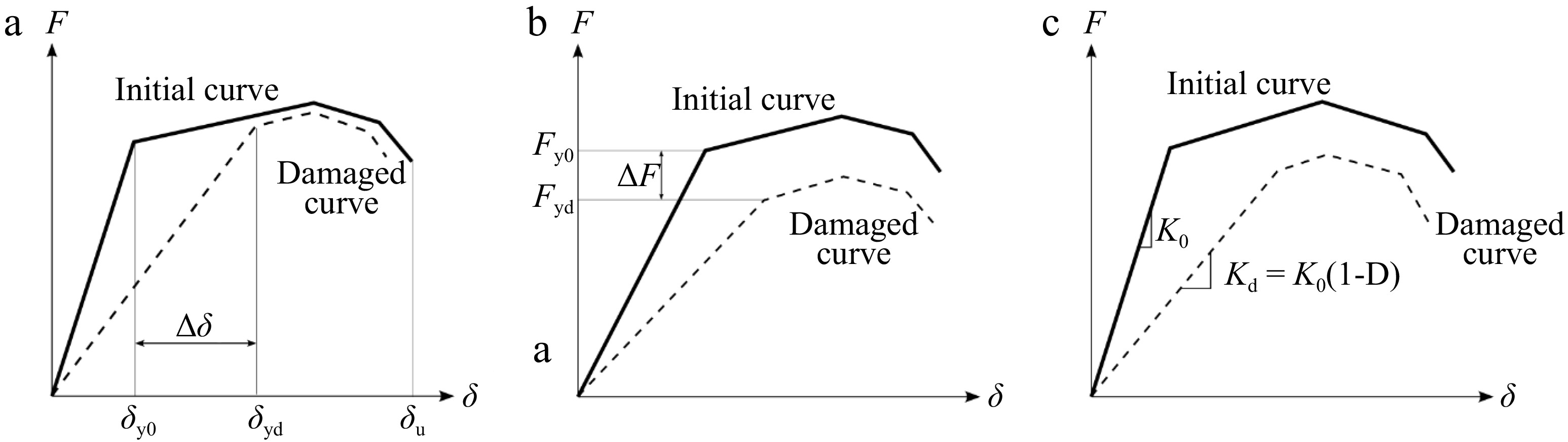
Figure 2.
Different strategies for damage identification. (a) Change in displacement patterns; (b) Reduction in bearing capacity; (c) Reduction in stiffness.
● Variation of displacement response, see Figure 2a: The damage concerns the ductility levels. It depends on the reference displacements, e.g., yield or peak displacement, at the initial and at the damaged state[28]:
$ {\boldsymbol{D}}=1-\dfrac{{\delta }_{y0}}{{\delta }_{yd}} $ (4) ● Decrease in bearing capacity, see Figure 2b: It concerns the strength reduction, and expresses the variation between the initial (Fy0) and the damaged (Fyd) yielding strength, for instance[29]:
$ {\boldsymbol{D}}=1-\dfrac{{F}_{yd}}{{F}_{y0}} $ (5) ● Variation in modal properties: Procedures based on modal properties are mainly indicated for global damage, without any need for local damage indices[30,31] .
● Stiffness reduction, see Figure 2c: Damage may also be represented by the decrease in the elastic slope of the curve representing the overall (or local) behavior of the structure (or component). Thus, D depends on the initial undamaged stiffness K0 and the damaged stiffness Kd[32] :
$ D=1-\dfrac{{K}_{d}}{{K}_{0}} $ (6) Mechanical approach adopted for framed structures
-
The present paper focuses on the case of framed structures. The paper evaluates the exact global damage, by the so-called mechanical approach, as the stiffness change of the first-mode capacity spectrum obtained from a pushover analysis[31] . The adopted overall procedure, illustrated in Figure 3, consists of computing an index (Global damage: DG) ranging from 0 (no damage) up to 1 (complete damage) by setting on the mechanical model of the building, local damage indices Db and Dc for beams (Bj,k) and columns (Ci,k), with: i in [1..NB], j in [1..NC], k in [1..NS], NB and NC = respective numbers of beams and columns in each story, NS = number of stories.
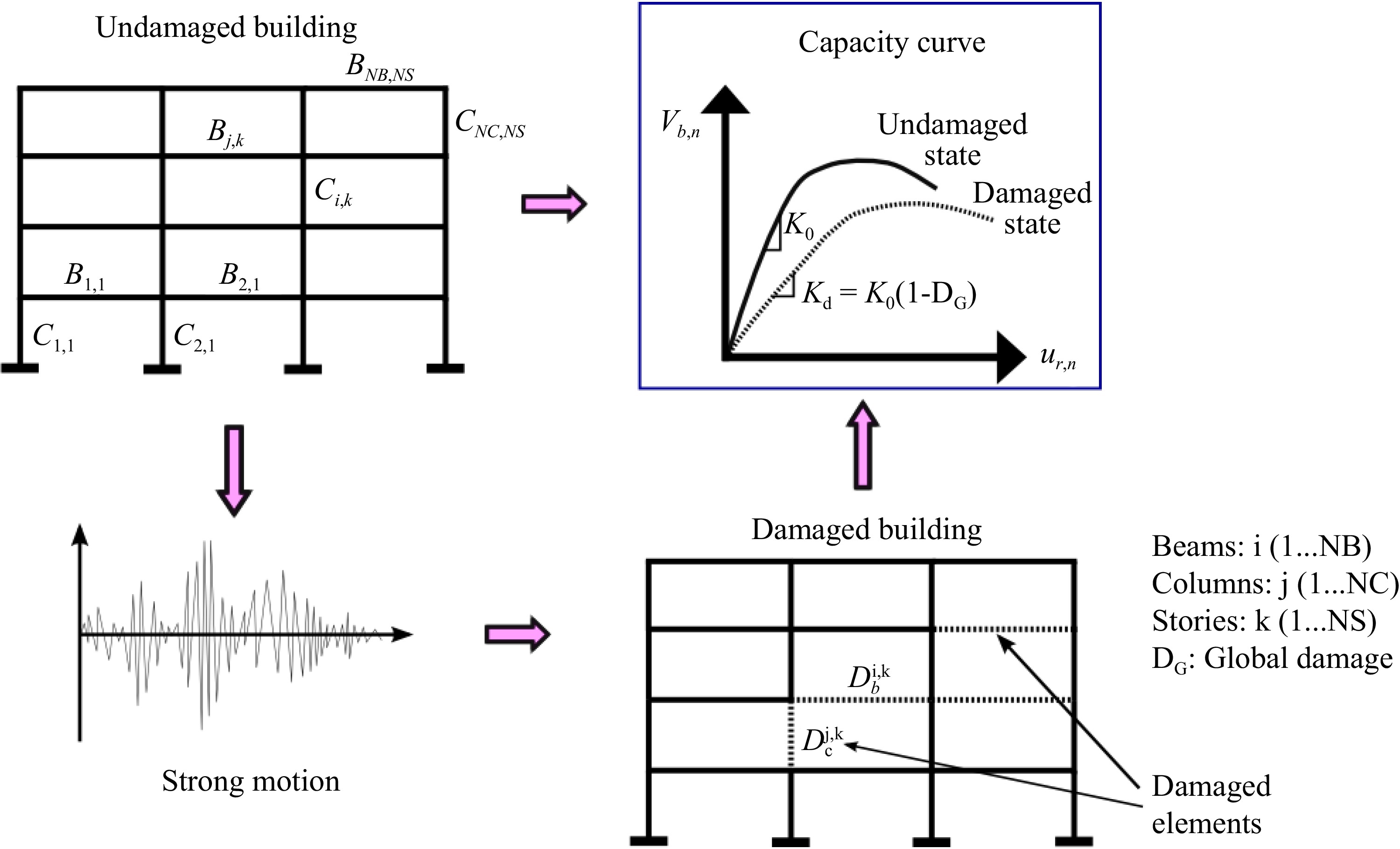
Figure 3.
Evaluation of global damage through the changes in the capacity curve stiffness.
For the bending behavior of the framed structures, the nonlinear behavior of the constitutive elements (beams and columns) is controlled through the plastic hinges. It is approximated by a bilinear elastic-plastic hardening curve, with neither coupling between damage and elasticity, nor between damage and hardening. The damage value D already expressed in Eqn (6)[32] , expresses the secant stiffness reduction, see Fig. 4:
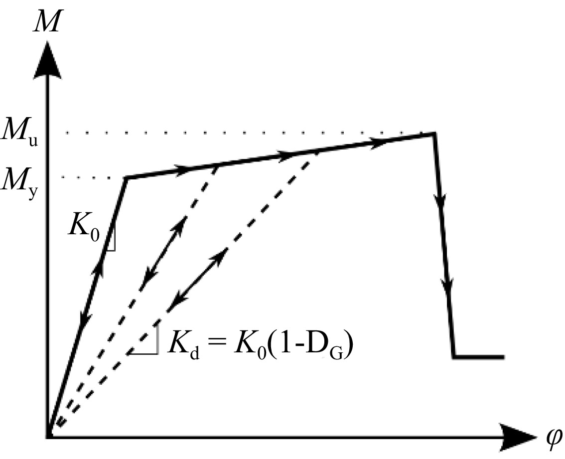
Figure 4.
Nonlinear degrading model used to simulate damage on beams and columns.
$ M=K_0\times\left(1-\boldsymbol{D}\right)\times\phi $ (7) where, M: the bending moment; K0: the elastic stiffness, and ϕ: the curvature of the section at the plastic hinge location.
Review of some empirical and simplified approaches
-
Damage measures can be defined in several ways, on an explicit mechanical basis or by simplified empirical indicators. For this latter category, the damage indicator may be a function of the remaining life span of the structure, expressed in terms of economical indices as a function of repair costs or related to residual probabilities of failure[2,4,25,33]. Some authors have proposed a new model that can be used to predict the mean and desired prediction limits of the losses for a given intensity level as well as to create fragility functions[34].
Furthermore, in order to combine different possible causes of damage, some authors propose an evaluation of the frames components damage by[35]:
$ \boldsymbol{D}_{tot}=1-\left(1-D_{fl}\right)^{\alpha}\times\left(1-D_{sh}\right)^{\gamma} $ (8) with:
$ \alpha =\gamma =1 $ (9) where, Dfl and Dsh stand for the flexural and the shear damage indices, respectively; α and γ, are importance factors weighting the influence of flexural and shear damage index on the total local index.
The local damage, i.e. at the component level, need then to be combined in order to derive a global index[36]:
$ {\boldsymbol{D}}=\mathop\sum\nolimits_{i=1}^{N}{\lambda }_{i} \times {D}_{i} $ (10) with:
$ {\lambda }_{i}=\dfrac{{W}_{i}}{\sum _{i=1}^{N}{W}_{i}} $ (11) where, D is the global damage of a system consisting of N components with local damages Di; Wi stands for the value of the selected average criterion for the i-th element.
A global index must reflect the damage concentration, in weak regions of the building, as well as its spatial distribution. Thereby, as damage distribution is known to be related to the absorbed energy distribution, which energy Ei has been used as an averaging criterion (Wi = Ei, either for a whole story or at a finite representative volume)[37−39] . This approach is particularly adapted to detailed studies of damage within a finite element framework, where local indices relate to material deterioration.
For some authors, the weighting factors should consider the consequences of significant damage in lower stories on the structural collapse. Therefore, Wi is defined as the tributary gravity load supported by each element. Such a scheme seems rational and intuitive since it considers simultaneously that damage in lower stories and in columns has the largest influence on global damage[40].
Finally, recent probabilistic approaches estimate the global damage from damage of both structural and non-structural components by means of the residual probability of failure[1,2,4−7,27,41]. These methodologies applied to a database collected by in situ evaluations corresponding to the 2003 Boumerdès Earthquake (Mw = 6.8, Algeria; ~50,000 post-quake evaluation forms collected and processed) provide theoretical damage that are in accordance with the observed damage. They have the advantage of transforming quickly and in a simple way, qualitative measures of damage into a quantitative index. They can be implemented in the post-earthquake assessment process to be a decision-making support for post-seismic forensic evaluations.
-
The new approach, developed and proposed in the present paper, considers the framed building as a series of successive layers, i.e., NS stories from bottom to top. Each story results in itself by serial or parallel combination and disposal of elementary components i.e. NB beams and NC columns, see Fig. 5. For such disposal, the probability of failure of the structure can be described as follows[5,6], see Figs 3 & 5:
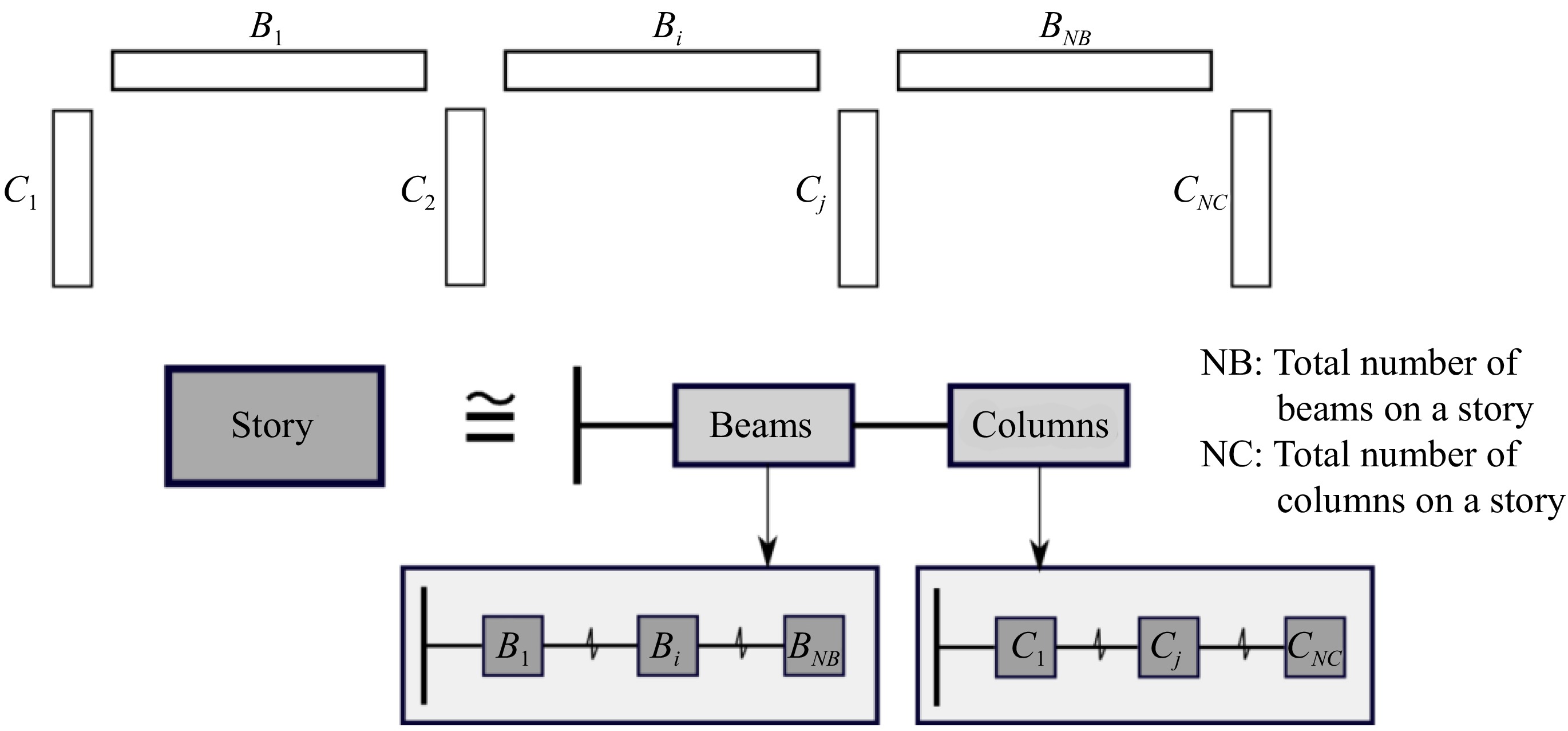
Figure 5.
Story series system of NB beams and NC columns.
● Global failure of the framed structure: The structure is considered as failing whenever any story fails, so that:
$ {E}_{G}=\mathop\bigcup\nolimits _{k=1}^{{N}_{S}}{E}_{s,k} $ (12) where, EG corresponds to the probabilistic event 'Failure of the Structure' (with the corresponding probability PG), Es,k = event 'Failure of the k-th story' (with the corresponding probability Ps,k), where, k in [1..NS], NS being the total number of stories.
Under the conservative hypothesis of independent events, the probability corresponding to the event 'EG' is then:
$ {P}_{G}=1-\mathop\prod\nolimits _{k=1}^{{N}_{S}}({1-P}_{s,k}) $ (13) ● Individual story's failure: The structure is considered as failing whenever any beam or column (serial disposal) fails at the current story, so that:
$ {E}_{s,k}={E}_{b,k}\cup {E}_{c,k} $ (14) where, Eb,k and Ec,k corresponds, respectively, to the probabilistic event 'Failure of a beam or a column' (with the corresponding probability Pb or Pc, respectively).
Under the conservative hypothesis of independent and disjoint events, the probability corresponding to the event 'Es,k' is then:
$ {P}_{s,k}=1-\left\{\mathop\prod\nolimits _{i=1}^{{N}_{B}}{(1-P}_{b,i})\right\} \times \left\{\mathop\prod\nolimits _{j=1}^{{N}_{C}}{(1-P}_{c,j})\right\} $ (15) The global risk of failure for the whole structure becomes:
$ {P}_{G}=1-\mathop\prod\nolimits _{k=1}^{{N}_{S}}[\left\{\mathop\prod\nolimits _{i=1}^{{N}_{B}}{(1-P}_{b,i})\right\} \times \left\{\mathop\prod\nolimits _{j=1}^{{N}_{C}}{(1-P}_{c,j})\right\}] $ (16) Development of a relationship between damage and residual probability of failure
-
By similarity with the efficient probabilistic approach, which relates the components' damage to the failure risk through an adequately calibrated relationship[5,6], a relationship between the elementary probability of failure, Pe and the damage index for a component or a system, De is proposed and calibrated for the present paper. It considers a factor αe to express the influence of the component on the global system's behavior:
$ {1-P}_{e}={(1-{D}_{e})}^{{\alpha }_{e}} $ (17) It may be observed that this equation fulfils a coherent correspondence between probability of failure and damage, i.e. when there is no damage, there is no failure (Pe = 0), and when the damage is considered as complete (De = 1), then the component or system fails (Pe = 1), regardless of the value of αe.
According to Eqns (12)−(16), and defining αb and αc as the respective importance factors of beams and columns, the damage can be evaluated as follows:
● Individual damage at each story: The damage of the k-th story becomes:
$ {D}_{s,k}=1-\left\{\mathop\prod\nolimits _{i=1}^{{N}_{B}}{(1-{D}_{b,i})}^{{\alpha }_{b,i}}\right\}.\left\{\mathop\prod\nolimits _{j=1}^{{N}_{C}}{(1-{D}_{c,j})}^{{\alpha }_{c,j}}\right\} $ (18) ● Global damage of the structure: The global damage of the structure depends then also on the story's importance factor βk, so that:
$ {D}_{G}=1-\left\{\mathop\prod\nolimits _{k=1}^{{N}_{S}}{(1-{D}_{s,k})}^{{\beta }_{k}}\right\} $ (19) It is worth noting that the damage is assumed to be uniform along each individual component, i.e. along a beam, along a column, or at a story. As a consequence, for the sake of simplicity, when the damage is concentrated on the edges (supports) of a column, for instance, the damage is supposed to be equal to that maximum damage all along the considered column.
Determination and calibration of the individual importance factors
-
The importance factors express the relative influence and importance of each component (beam and column influences) on the story's and global levels (individual stories influence). The following assumptions are then adopted:
● Importance factor of the story, β: From Eqns (10)−(11), the adopted importance factor is related to the gravitational load supported by the current k-th story[28,40]. It reflects the important risk and consequences of collapse of the lower stories:
$ {\beta }_{k}=\dfrac{{W}_{k}}{\sum _{l=1}^{{N}_{S}}{W}_{l}} $ (20) with:
$ \mathop\sum\nolimits _{k=1}^{{N}_{S}}{\beta }_{k}=1 $ (21) ● Importance factor of the beams and columns at each story, αb and αc: The stiffness and strength deterioration influence the damage. In the present study, the stiffness is considered as the reference parameter for estimating and calibrating the importance factors. The influence of the damage affecting a component depends on the contribution of the element (beam or column) on the lateral stiffness of the story. For a one-story, one-bay frame with rigid supports, it is possible to derive the following expression by neglecting the axial and shear deformations of elements (see Appendix 1)[42,43]:
$ K_L=\dfrac{24\times E}{L_c^2}\times\left(\dfrac{\rho_c^3+6.5\rho_b\rho_c^2+3\rho_b^2\rho_c}{4\rho_c^2+8\rho_b\rho_c+3\rho_b^2}\right) $ (22) where, ρc = Ic/Lc and ρb = Ib/Lb represent, respectively, the relative stiffness of columns and beams, computed as the ratio between the second moment of area of the cross section (I) and the length of the element (L); E represents the Young's modulus (assumed herein as being the same for all the elements, for simplicities sake).
where, h is the story height and Ic,j represents the second moment of area of the cross section of each column j. As stated previously[44], the lateral stiffness does not depend on the beam length. For this case, one may consider that columns have their maximum contribution, i.e. the maximum importance.
$ {K}_{L,k}^{max}=\dfrac{12.E}{{h}^{3}} \times \left(\mathop\sum\nolimits_{j=1}^{{N}_{c}}{I}_{c,j} \right) $ (23) where, h is the story height and Ic,j represents the second moment of area of the cross section of each column j. As stated previously[44], the lateral stiffness does not depend on the beam length. For this case, one may consider that columns have their maximum contribution, i.e. the maximum importance.
On the other hand, when the stiffness of beams is almost negligible so that there is no restriction to lateral displacements, the minimum lateral stiffness value tends to:
$ {K}_{L,k}^{min}=\dfrac{3.E}{{L}_{c}^{3}} \times \left(\mathop\sum\nolimits _{j=1}^{{N}_{c}}{I}_{c,j} \right) $ (24) For this latter case, the lateral stiffness value also depends only on columns' stiffness. As the columns' contribution is the smallest possible, then the associated importance must be the minimum. Therefore, since the current lateral stiffness KL for a given configuration ranges between these two bounds, smaller than
$ {K}_{L,k}^{max} $ $ {\alpha }_{c}=\dfrac{{K}_{L}}{{K}_{L,k}^{max}} $ (25) Of course, this is a first approximation since the computation of the 'real' influence is much more complex, and depends on all the connected elements to the columns under study. Thereby, as the summation of the importance factors for all the considered components must be equal to 1 regardless of the chosen property, the influence factor of beams is:
$ {\alpha }_{b}=1-{\alpha }_{c} $ (26) Getting an explicit expression for lateral stiffness, as Eqn (22), is not feasible for taller frames. Therefore, simplified expressions for KL are required in order to compute the αc factor, for those cases. Several simplified relationships may be used in order to estimate the lateral stiffness of each story as a function of the mechanical and geometrical properties. In the present case, a version of the Wilbur formulas has been used[42,43,45]. They are simplified expressions based on some assumptions, which are not completely respected in some cases (see Appendix 1). Nevertheless, since only an estimate of the influence of elements on the lateral stiffness is required, their use is considered as enough suitable in this case.
Finally, the individual factors αb,i and αc,i are computed by dividing the αb and ac factors by the number of beams and columns, NB and NC, respectively.
Operational procedure
-
The whole operational procedure can be summarized as follows:
● Initial steps
(1) Collect the data of local damage for each element of each story.
(2) Obtain the mechanical and geometrical properties of the components: Young's modulus E, cross-section dimensions b (width), h (height), and elements' length L.
(3) Estimate the gravity loads Wk carried by each story k-th where k = 1 up to NS.
● Calculate the importance factors of the beams and columns at each story: αb and αc factors
(4) Estimate the lateral stiffness of each story (e.g. by means of the Wilbur's Formulas, see Appendix 1).
(5) Compute the theoretical maximum lateral stiffness of each story.
(6) Compute the importance factors αc and αb.
(7) According to the number of beams NB and columns NC, compute the individual factors αb,i and αc,j.
● Calculate the importance factors of each story: β factor
(8) From the information obtained in step 3, compute the β factor.
● Calculate the story's damage and structure's global damage
(9) Estimate the damage at each story, from the information of local damages obtained in step 1 and the αb,i and αc,j factors obtained in step 7.
(10) Finally, compute the global damage DG, from the story damage Dk and the β factor from step 8.
-
For illustrative purposes, two frames are chosen in order to analyze the effect of a single damaged element on the global damage index.
● First case: 1-story, 1 bay reinforced concrete frame
The first case represents a 1-story, 1-bay reinforced concrete frame with cross section dimensions of 30 cm × 40 cm (1,200 cm2) for the beam and 40 cm × 40 cm (1,600 cm2) for the columns. Different values of local damage are applied to affect, according to the case: only the beam, only one column, the beam and one column (1b1c), and finally both columns. The results show that a beam with 50% of damage causes 17% of global damage, while such an extent of damage on the beam and one column produces a global index of about 36%, see Fig. 6. When dealing with columns only, a single column with 50% of damage means 23% of global damage while if this level of damage is applied to both columns, the effect overall structure is about 40%. These values are quite logical since they demonstrate the impact of each element on the global behavior and reflect the structure's redundancy.
Figure 6.
Influence of local damage at each element on a 1-bay, 1-story frame.
● Second case: 4-story gravity-load designed frame (GLD)
The second case analyzes the effect of the localization of the damage element on the global index, in the case of a 4-stories gravity-load designed frame (GLD), which has been experimentally tested under seismic loads in the European Laboratory for Structural Assessment (ELSA)[45] , see Figs 7 & 8. Figure 8 represents the variation of the global damage index as a function of local damage and the story where the element is located. A single point in that figure reflects the global damage when a single element is considered as damaged in a single story, a beam in Fig. 8a, and a column in Fig. 8b. According to these results, as intuitively expected, one may notice that global damage increases as local damage increases, and it decreases as long as the damaged element is located at a high story. Thus, when applying the proposed strategy, a 30% damaged column on the first floor will produce a story damage of 6% and a global damage of 2.5%. The latter value may appear as too low as being the influence of a column in the first floor. However, it reflects the relative importance of one column in a story containing three beams and four columns, within a 4-story building.
Figure 7.
Elevation view of the 4 GLD building.
Figure 8.
Global damage index when a single element is damaged: (a) beams, (b) columns.
When the damage is concentrated in a single beam, the results are not exactly what might be expected, mainly for the first floor. In fact, Wilbur formulas overestimate the stiffness at the ground floor due to a fixed rigid foundation. It causes, therefore, an overestimate of the αc factor and the underestimate of the αb factor, which causes in turn a sharp gradient between these factors between the first and the second story. That is why, according to Fig. 8a, a damaged beam on the second floor produces a higher global damage index in comparison to a beam damaged on the first floor.
Comparison between mechanical approach and the new simplified approach: applications
-
For illustrative purposes, the proposed simplification is applied to the same case, i.e., the 4-story GLD building, under a specific pattern of damage, see Table 1. It consists of concentrated damage in the first and second stories: values of damage of 30% for the beams and 20% for the columns in the first story, and 15% for all the constitutive elements in the second story, are applied. The importance factors as well as the stiffness of each story are calculated according to the proposed procedure, see Table 1. Since the damage is concentrated at in the first two stories, only D1 and D2 have a non-zero value, computed as:
Table 1. Damage pattern and global damage estimation of the 4-story GLD frame.
Story Individual damages Importance factors Damage Beam Columns Beam Column Story Story Global 1 2 3 1 2 3 4 αb,i αc,j βk DS,k DG 1 0.3 0.3 0.3 0.2 0.2 0.2 0.2 0.10 0.17 0.41 0.23 0.146 2 0.15 0.15 0.15 0.15 0.15 0.15 0.15 0.16 0.13 0.30 0.15 3 0.12 0.16 0.09 0.00 4 0.12 0.16 0.09 0.00 $ {D}_{1}={D}_{s,1}=1-\left\{\mathop\prod\nolimits _{i=1}^{{N}_{B}=3}{\left(1-0.3\right)}^{0.1}\right\} \times \left\{\mathop\prod\nolimits _{j=1}^{{N}_{C=4}}{\left(1-0.2\right)}^{0.17}\right\}=0.23 $ (27) $ {D}_{2}={D}_{s,2}=1-\left\{\mathop\prod\nolimits _{i=1}^{{N}_{B}=3}{\left(1-0.15\right)}^{0.16}\right\} \times \left\{\mathop\prod\nolimits _{j=1}^{{N}_{C=4}}{\left(1-0.15\right)}^{0.13}\right\}=0.15 $ (28) As expected, the second story damage index is equal to 0.15 since all the elements are assigned this value as local damage. Finally, based on the stories' damages, the global damage is then:
$ D_G=1-\left(1-0.23\right)^{0.41}\times\left(1-0.15\right)^{0.30}\times\left(1-0\right)^{0.20}\times\left(1-0\right)^{0.09}=0.146 $ (29) The global damage estimated by the probability-based approach is then compared with the mechanical damage obtained by the nonlinear push over analysis. The local damage index is set for each element according to the deterioration model. Subsequently, a pushover analysis is performed to obtain the capacity spectra for the undamaged and the damaged frame, see Fig. 9. Finally, the average damage is computed as a function of the elastic stiffness of these two curves:
Figure 9.
Capacity spectra of the 4-story GLD frame.
$ {D}_{G}=1-\dfrac{{K}_{d}}{{K}_{0}}=1-\dfrac{53.2}{62.4}=0.148 $ (30) A very small difference is found for this particular case: about 1.4% of difference between the proposed method result and the push-over analysis.
-
As shown in Fig. 10, the three types of columns i.e. edge columns, exterior columns and interior columns, have different tributary areas (the loads that are carried by a column ), which means that the interior columns transfer the highest loads (the biggest tributary area in this example), and that leads us to ask the question : do all the columns have the same effect on the global damage index ?
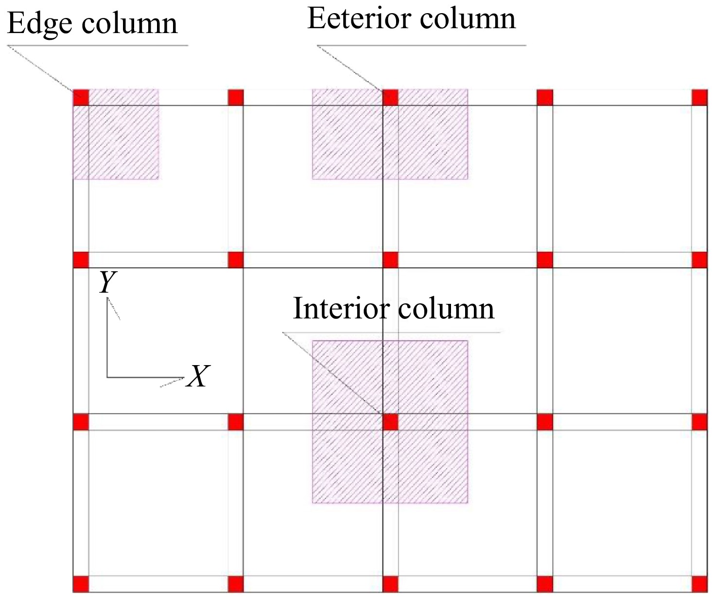
Figure 10.
Tributary areas for columns: "Edge, exterior and interior" column.
In this section, three storeys building with four bays, 06 meters in length and 03 meters in height (see Figs 11 & 12), are used to perform pushover analysis in x-x direction. For each, a damage is located in one of the columns, and the global damage index will be calculated using the mechanical approach [see Eqn (6)]. The damage consists in reducing the column's area (concrete area + rebar area) (see Fig. 12).
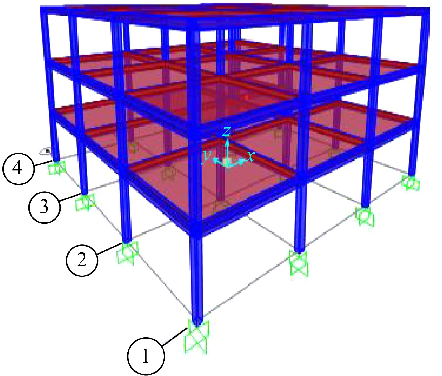
Figure 11.
The 3D building.
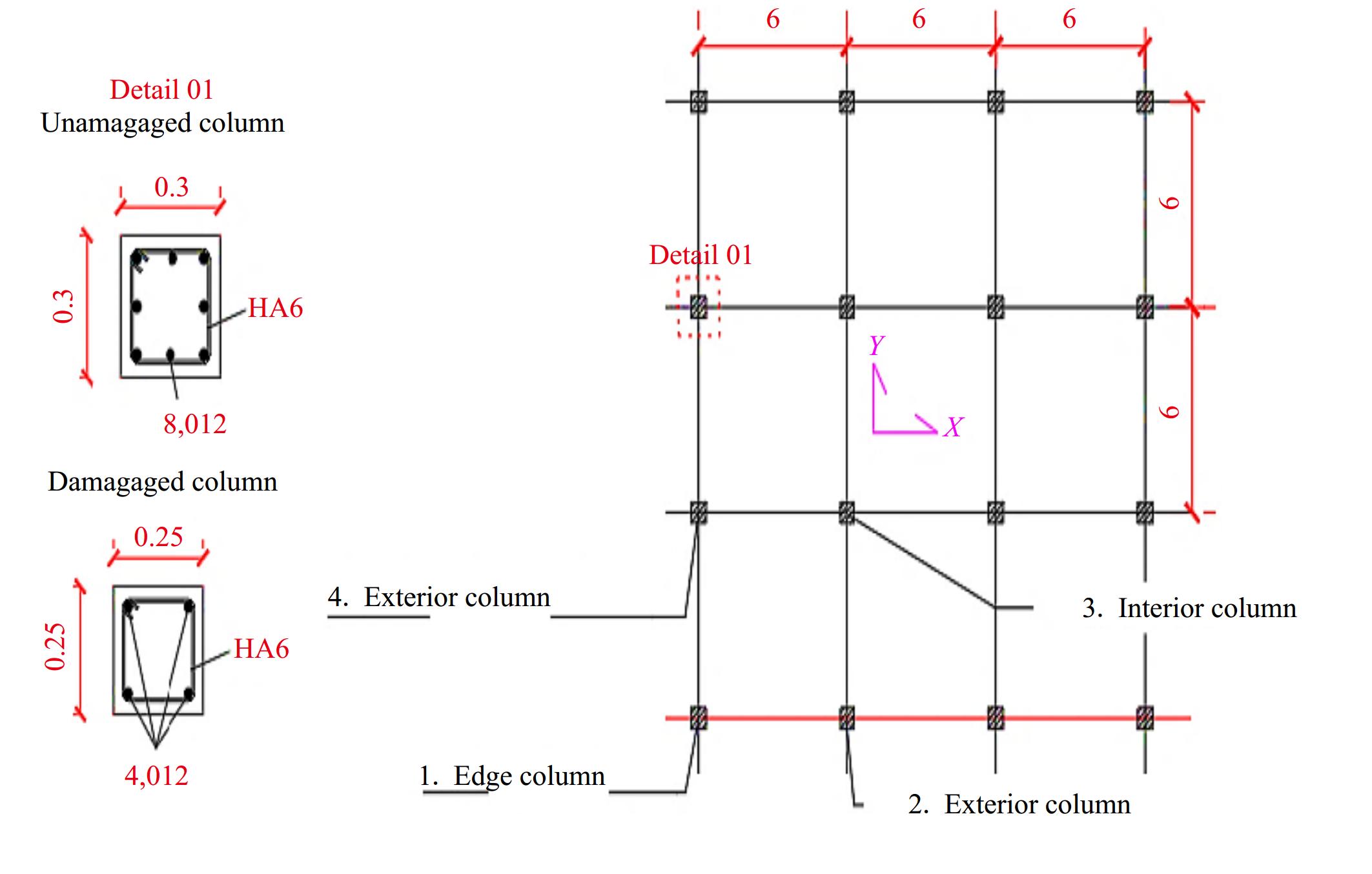
Figure 12.
The building's layout (x-y plan) and the cross section of 'undamaged and damaged column'.
Discussion and results
-
After performing 12 pushover analysis and calculating the global damage indices (edge column, exterior column (x-x) direction, interior column, and exterior column (y-y) direction) of the three storeys (see Fig. 13), four points can be concluded:
(1) According to Fig. 13, the columns of the first story have biggest impact in term of global damage index DG = {0.0149-0.017-0.021-0.006} for the edge column, Exterior columns 'x-x direction', Interior columns, and Exterior columns 'y-y direction' respectively at the first story.
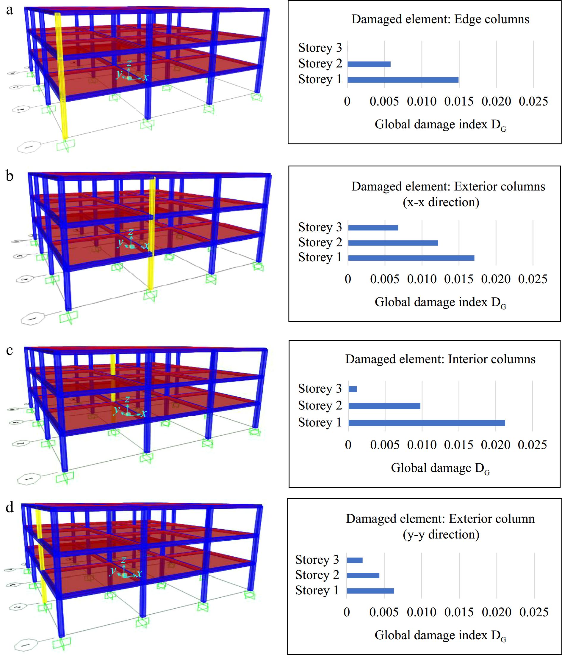
Figure 13.
The effect of the damaged column's position on the global damage index DG: (a) Edge columns, (b) Exterior columns (x-x), (c) Interior columns, (d) Exterior columns (y-y).
(2) The edge columns have the smallest effect on the global damage index, DG = {0.0149, 0.0058, 5.32e-05} for the 1st, 2nd, and 3rd storey respectively. It means that if the damage is located in these types of columns, the initial stiffness will not be changed significantly.
(3) The interior column for the first floor has the highest global damage index DG =0.021, which means that the damage of interior columns has the biggest effect on the index.
Based on Figs 12 & 13, not all the columns have the same effect on the building's global damage index. The more the column is located in lower stories the more it carries and transfers more gravity loads, for that reason, an important factor has been introduced in this theoretical approach to consider the effect of the carried load of each story.
However, the proposed approach considers that the local damage of one element (columns in this case) has the same effect on the global damage index, and it does not matter if this damaged column is an interior or an exterior element of the same story.
Since the tributary area changes from a column to another, the carried loads by the columns are not the same at the same story, so the importance of these type of elements are not related by which floor are located but which position they occupy.
Figures 12 and 13 demonstrate that the global damage index and the position of the damaged column are related indeed. It is illustrated clearly in the values of the global damage indices of story 1 (the same conclusion for stories 2 and 3).
As is proven in this study, the importance factor of the story should also take into consideration the effect of the position of the damaged columns not only the stories' importance (the gravitational load supported by the story). Furthermore, it should also reflect the consequences of collapse of a column that carries a huge gravitational load (central/interior first story columns for example).
It is highly recommended that the next update of this theoretical approach will consider this effect, in order to obtain results that are as close as possible to reality. Actually, these results are promising in reaching a new generation of evaluation forms for quick inspection in the early hours and days in the aftermath of a disaster[9,46−49].
-
The present paper has related the seismic damages, suffered by buildings, to the resilience. The drop of utility functions, concerning the dwelling and provisional sheltering at early post-quake stages, can be overcome by adequate management of available resources, such as adequate transfer from non-vital activities to dwelling and sheltering purposes before total recovery and reconstruction. The quick and accurate evaluation of the buildings that can still remain in service, and those to be evacuated or demolished requires the development of efficient methods able to identify the category of damage quickly in the aftermath of a disastrous event.
For this purpose, a probability-based strategy has been developed with the aim of computing global damage indices on the basis of the constitutive component's damage. An adequate relationship between the structural damage and the residual probability of failure is developed. It proposes influence factors to express the relative influence of the damage of each constitutive component on the whole damage. The results obtained by an analytical approach which considers the reduction in the capacity spectrum stiffness as an indicator of global damage are taken as reference results for calibration purposes.
A good accordance between the estimation and the reference result was obtained for a 4-story building. This result shows the good efficiency of this approach on the considered examples, though further validation on various typologies can be investigated: other constitutive materials (metal, reinforced concrete, etc.) with different heights 4-, 6-, 8-story frames, and more.
Lastly, since the importance factor of the story was introduced in the proposed approach that tackles the effect of the damage location in the story. A study is made to see if there is a correlation between the location of the damaged column in the story and the global damage, for that reason, a 3 story building with 3 m × 6 m bays were proposed to simulate 12 possible damage scenarios by assigning a damaged cross section to one column each time from four possible location (edge-exterior in both directions (xx,yy) and interior columns) for all the stories. As a result, 12 global damage indices were calculated using the mechanical approach, and it was concluded that the location of the damaged columns has an effect on the global damage even if the local damage of the columns is the same, i.e., the global damage when the interior column (of the first story for example) is damaged is more important than the damage if it is located in the edge or exterior columns with the same amount of the local damage index. For that reason, it is recommended to introduce this effect in the theorical approach to have results that match the mechanical approach precisely.
The present method intents to provide a scientific basis in order to improve the existing evaluation forms for quick visual inspection. It proposes a scientific way, based on structural mechanics, to support the damages classifications and to be able to relate the damage of the individual elements (beam and column for framed structures) to the damage of the whole storey relate afterwards the damage of the story (its location is of crucial importance) the the global damage of the whole structure. It is, in its current version, limited to the case of framed structures. Extension to shear walls and other typologies needs further developments.
In conclusion, this strategy has the potential of being part of a decision-making tools, which helps in performing fairly accurate assessments of global damage based on adequate combinations of the constitutive components damage. Particularly, since only some geometrical and mechanical properties of the structure are required, its use for post-seismic evaluation of damage is also feasible by means of its implementation on interactive devices (such as: smartphones, electronic tablets, etc.) with GIS tools, on large scale as urban constructions after the occurrence of an earthquake.
-
The authors confirm contribution to the paper as follows: supervision, coordination of the whole study: Mebarki A; development of theoretical aspects, methodology, case studies selection, results analysis: Mebarki A, Jerez S, Benbokhari A; simulations running (under Opensees and Matlab): Jerez S, Benbokhari A; draft manuscript preparation: Jerez S; draft manuscript preparation (related to the effect of the columns location in the building): Benbokhari A; manuscript revision, suggestion to case studies for the methodology validation: Boukri M, Chikh B. All authors reviewed the results and approved the final version of the manuscript.
-
All data generated or analyzed during this study are included in this published article.
-
The authors declare that they have no conflict of interest. Mebarki A is the Editorial Board member of Emergency Management Science and Technology who was blinded from reviewing or making decisions on the manuscript. The article was subject to the journal's standard procedures, with peer-review handled independently of this Editorial Board member and the research groups.
- Appendix1 Wilbur’s Formula.
- Copyright: © 2024 by the author(s). Published by Maximum Academic Press on behalf of Nanjing Tech University. This article is an open access article distributed under Creative Commons Attribution License (CC BY 4.0), visit https://creativecommons.org/licenses/by/4.0/.
-
About this article
Cite this article
MEBARKI A, JEREZ S, BOUKRI M, CHIKH B, BENBOKHARI A. 2024. Emergency management and urban resilience under seismic risks. Part I: Theoretical approach for quick post-quake damage evaluation of buildings. Emergency Management Science and Technology 4: e027 doi: 10.48130/emst-0024-0027 

Emergency management and urban resilience under seismic risks. Part I: Theoretical approach for quick post-quake damage evaluation of buildings
- Received: 01 August 2024
- Revised: 17 October 2024
- Accepted: 22 October 2024
- Published online: 25 December 2024
Abstract: This paper addresses topics related to emergency management and urban resilience under seismic risk. It focuses on post-seismic structural damage evaluation and urban resilience: the damage suffered by buildings influence the residual capacity for dwelling and sheltering at early post-disaster stages. This paper proposes a new theoretical method for quick evaluation of these damages: it derives the global structural damage from the observed damage on the structural components of a frame, i.e. beams and columns (vertical components, horizontal, or bracing elements). The global residual capacity of the building is derived from those of the successive stories: from the basement to the roof. Therefore, it proposes a relationship between the structural damage and the residual probability of failure. It also develops and assigns adequate importance factors for each component (beam, column), at the story level, and importance factor for each story and its location, from bottom to top. The proposed method is compared with classical mechanical approaches: the global damage values are in good accordance, for the adopted case studies. Furthermore, a pushover analysis is performed in order to investigate the influence of the columns' location at the story level: the column's influence it located at the edge, interior, or exterior location. The investigation of the effect of the column location in a story, of the story location along the building height, will contribute in developing new quick evaluation forms at the post-seismic stage and allow quick recovery at the urban scale.
-
Key words:
- Seismic risk /
- Urban resilience /
- Buildings /
- Post-disaster management /
- Structural damages